
Implementation of a Levitation System for the Visualization of the Magnetic Phenomenon
Volume 5, Issue 5, Page No 302-307, 2020
Author’s Name: Zeila Torres Santos1, Brian Meneses-Claudio2,a)
View Affiliations
1Interdisciplinary Research Center Science and Society (CIICS), Universidad de Ciencias y Humanidades, 15314, Perú
2Image Processing Research Laboratory (INTI-Lab), Universidad de Ciencias y Humanidades, 15314, Perú
a)Author to whom correspondence should be addressed. E-mail: bmeneses@uch.edu.pe
Adv. Sci. Technol. Eng. Syst. J. 5(5), 302-307 (2020); ![]() DOI: 10.25046/aj050538
DOI: 10.25046/aj050538
Keywords: Magnetic Levitator, Electromagnet, Electronic Circuit, Differential Potential

Export Citations
The phenomenon of magnetic fields is affected depending on the polarity, the positive and negative poles will give a response of attraction and repulsion that can be easily observed. Being also important as an educational element where the theory materializes and is observed, which enriches all science. The objective of this work is to create a circuit that allows reaching the balance between the electronic components, making use of the fundamental electronics together with an LDR and a light sensor. Both generate a connection bridge in which the object that levitates to remain in the air fluctuates, achieving the objective of creating a levitator and being able to observe the nature of electronics and electromagnetism as a whole. As a result, it was obtained that there is a difference between the use of basic and advanced electronic circuits, in addition to identifying the variation in the voltage consumption between the coin and the screw, because the more voltage consumption, the greater the length of wave implying that the frequency decreases but the power intensifies. On the other hand, it should be noted that the use of a voltage generator to identify the voltage and power variations that were shown at the time of the different tests.
Received: 22 July 2020, Accepted: 11 August 2020, Published Online: 17 September 2020
1. Introduction
The interaction of electric and magnetic fields produces a phenomenon called Electromagnetism; this phenomenon is a topic of physics that describes the response of charged particles with these fields. The movement of electric charges generates a magnetic field, this field is also associated with the force such as the magnets, being this force of repulsion or attraction, allowing these latter responses to phenomena such as levitation, these fields have as their unit of measurement the volts per meter [1].
It can be ensured that the theory is incomplete when it does not have the experimental part to observe these phenomena, being important to have both scientific experimentations equally. The fact of designing and implementing a levitator is of such importance, to generate interest in students who like science or not, can observe physical phenomenon [2], being through electronics the possibility of synthesizing the device with the electronic devices basics, without the need to use modern electronic devices such as Arduino or similar.
Basic concepts such as that of Electromagnetism, is explained to students of engineering, physical sciences, mathematics and similar careers and even to students in the last years of school. According to a report [3], they indicated that the quality of the infrastructure of the study centers of a public university and a private university was 75% to 51% respectively, that is, public universities focus their teaching more on the part theoretical than a practical definitions of physical phenomena, on the other hand, private universities focus on the general explanation of the physical sciences because they do not consider it of much relevance, being a very important factor due is in these spaces where the theory is applied, because many students allege that science laboratories are poorly implemented because they do not have adequate instrumentation for the development of scientific experimentation. A most recent results in the PISA evaluation [4], show that it still needs a greater improve in the learning process since the important points for the technological development of a country are at the base scientific.
In [5], the author mentioned that Oersted in 1820 discovered an electric current exerts a force on a magnet. This was the beginning to understand the electromagnetism phenomenon. The charged particles in movement are the mean actors to the electric and magnetic performances to induce a property of two bodies attract or repel each other. But it is important to note that there are bodies called permanent magnets therefore it is not necessary to induce a current to charge it because internally they have an atomic structure of alignment which creates a strong magnet.
The materials have different properties due to their response to the induced magnetic force, the same happening regarding the electric force because the internal atomic structure could be aligned in the same or opposite direction, in a weak or strong way, working internally with an intrinsic physical property called spin.
In [6], the author presents the design and construction of a magnetic repulsion levitator controlled by Arduino, also using metal structures to keep the coil at an adequate height and perform levitation, also used Hall sensors and a PI controller, the union of these circuits causes the current to remain stable and controlled by the Arduino, thus operate the magnetic levitation. This work confirms the use of programmable electronic devices for the operation of a magnetic levitator by attraction.
In [7], the authors propose an electronic circuit with an electronic transformer capable of converting alternating current to direct current for the supply of the electronic circuit, in addition to the current control and therefore the electromagnetic field, they used a loop PID control closed, it means that they used the feedback of the same system for self-regulation. In addition, it presents the simulation signals that they obtained in the MATLAB Simulink tool, obtaining stable signals when the electromagnetic field was created while maintaining an object attached to the coil and distortion signals when it had the electromagnetic field without any object in its area of radiation.
In [8], the authors propose a closed loop system for the operation of a magnetic levitator by attraction through the use of an infrared linear communication sensor between transmitter and receiver, the main function of the receiver is to decrease its resistance to allow the passage of the current and activate the electromagnetic field. The use of the sensors for the stabilization of the metallic object has to be calibrated due to the high transmission range of the infrared sensor; they also indicate that it is beneficial because the ambient light will not affect the resistance variation of the receiving infrared sensor.
The main idea of this research work is to contribute to teaching, but even more to give fundamental electronics a main role and create a device that can arouse curiosity by being able to visualize the physical phenomenon of the electric and magnetic fields, which even when carried out by a team of researchers, its creation and operation is made possible. Also, the simulations were made in the electronic laboratory where the phenomenon and the variation of the values were studied.
In section 2, the theory as well as the formulas is explained in detail, used to study the applied physical phenomenon. Then in section 3, the dimensions of the levitation system will be shown in detail, as well as the designs prior to its implementation. Later in section 4, the design of the electronic circuit for the magnetic levitation system will be shown, it should be noted that this design was made by constantly testing the electronic devices verifying their improvement. Also, in section 5, the magnetic levitation system already implemented in a circuital and structural way is shown, where it also has to be careful with the distribution of the cables so that they do not hinder the operation of the circuit. Also, in section 6, the results of the operation of the attraction levitation system, the visualization of the variation of the electrical signals emitted by the coil and captured by an electronic oscilloscope are presented, in addition to the separation distance between the metallic object and the coil. Then in section 7, the conclusions of the research work are presented, reinforcing the tests that were made with the operation of the magnetic levitation system and some observations that were obtained in the experimental part. Finally, in section 8, the discussion of the research work will be shown, in addition to some recommendations and errors of the implementation process when the magnetic levitation system was working.
The implementation of the levitator was based on the theory of electromagnetism; formulas will be presented to identify the stabilization and calibration of metallic objects, and the formulas combine mathematical equations will help to accurately discover the physical quantities of voltages, sensitivities, electronic units and other useful components in the process. The use of the theory, implementation and simulation makes the research work relevant for educational and teaching purpose.
2. Theory
A design that gives us an idea of the forces that occur is shown in Figure 1:

Figure 1: Simplify scheme of the magnetic levitator with forces acting
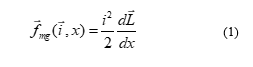
In equation (1) it has a mathematical expression related to Newton’s equation of motion, in this particular case, the levitation forces will be related to the electric current, inductance and the distance or position of the object to be levitated, that is , and . So, the equation is:
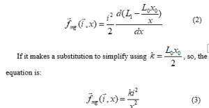
In equation (2), it can see that the terms of the inductance are added to the force depending on the object, that is, , being the inductance in the absence of the object to levitate and the inductance of the electromagnet in the equilibrium position , that is, making a first expansion in is:
According to Newtonian mechanics of a system, the sum of total forces exerted on an object that is with the effect of gravity must be equal to zero, that is, if it sees the object to be levitated in Figure 1, it can obtain the following equation:
![]()
Taking as reference the up direction as positive and the down direction as negative from the point of the object to levitate:
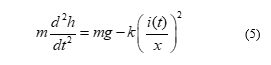
Where indicates the height of the object or gap.
Since the system indicates that it must apply Kirchhoff’s law because it has an electric circuit and an inductor , Ohm’s law and Faraday’s law for a closed RL circuit, it has again a differential equation:
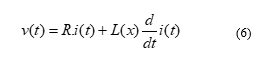
Thus, with equations (5) and (6), it will have a system of two equations that allow to understand the laws of motion of the object to be levitated. Which according to [2] it will be possible to construct equations of state in the state space according to the degrees of freedom of the system.
3. Structure Design of the Magnetic Levitation System
The system of Magnetic Levitation by Repulsion tends to have structures where the coil has an adequate height where in the lower part the metallic materials can be located so that they can be magnetized by the electromagnetic field generated by the coil.
For this reason, the structure for the system was designed in the SOLIDWORKS software, which gives us a broader view on the location of the components, in addition this design was sent to a laser cutter, for the manufacture in MDF material following characteristics shown in Table 1. These dimensions were specified and then sent to be laser cut.
The design of the structure was in a simple geometry, which allows the student to observe the internal configuration, such as the electronic circuit, the positions of the photoresistors, the copper coil and the possibility of reproducing it. It is shown in the next Figure 2, the necessary conditions for the location of the electronic devices that will be implemented later in section 5.
Table 1: Graph representations
| Dimensions (L, D, W) | Thickness | |
| Base | 32 x 29 x 2 cm | 18 mm |
| Top Box | 22 x 8 x 10 cm | 4 mm |
| Side supports | 1 x 8 x 21 cm | 9 mm |
| Coil | 2 x 2 x 4 cm | Coiling |
It should be noted that the structure was built based on the dimensions of a Breadboard, this being useful for the initial test of electronic circuits, where all the components were located, in addition, a circular orifice was added in the front of the design structural for the location of the led as shown in Figure 2 (a), the response of this led will indicate with its lighting the exact time to generate the phenomenon of magnetic levitation. Also, in Figure 2 (c), the reader can see 2 circular orifices of 1 mm in size, where the positive and negative cables of the coil can be connected to the breadboard. Finally, 2 circular orifices were added at the left rear side as shown in Figure 4, these orifices were 3 mm in size to supply positive and negative voltage to the breadboard without the need to uncover the structure.
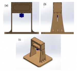
Figure 2: Design of the Structure of the Magnetic Levitator System by Attraction. (a) Front View. (b) Profile View. (c) Panoramic View.
4. Magnetic Levitation System Design
The design of an electronic circuit for a magnetic levitator [9] by attraction was proposed using an infrared sensor and an LED. These last two devices in the Proteus 8 software worked optimally but when it was implemented, errors were obtained with the sensors because the operating range did not adapt to the system, due to this it was changed to a photo-resistance and a red laser for current flow control.
The electronic components used for the design of the Levitation System are shown in the Table 2.
Table 2: Electronic Components
| Resistors |
· 1 x 330 Ω · 2 x 22 kΩ · 1 x 4.7 kΩ · 1 x 5.6 kΩ · 1 x 1.2 kΩ |
| Electric Capacitor |
· 1000 µf (microfarad) · 4.7 µf (microfarad) |
| Led Diode | · 2x Diode Led |
| TRIAC or Triode | · IRF510 |
| Rectifier Diode | · 1N5401 |
| Coil | · 3 millihenries |
| Operational Amplifier | · LM358 |
| Sensor | · Light Dependent Resistor (LDR) 1k Ω |
| Voltage Supply |
· 12 volts and 2 Amperes · -12 volts and 2 Amperes |
The electronic components were following the research work [2], in addition to the use of its equation but adding an LDR that is will serve as a sensor for the activation and deactivation of the levitation system.
As shown in Figure 3, the design of the previous research work was followed because this time with two different components that will be the sensors of our magnetic levitator circuit, in addition to indicating that it was verified that the consumption current of the electronic circuit was of 1 Ampere, this depended on the coil that was used.
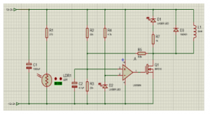
Figure 3: Design of the Electronic Circuit of the Levitation System.
Diode D3 is connected in reverse due to the requirement of the coil. In case of discharge, the diode can discharge the coil immediately, losing its magnetic field. Therefore, an immediate electric charge is required to levitate the metal object, the coil must be in constant operation of electric charge and discharge, depending on the sensors.
5. Magnetic Levitation System Implementation
After simulating the circuit in Proteus Software 8, the next step was the construction of the electronic circuit, a Protoboard was used for the location of all electronic components in addition to the correct voltage distribution. In addition, a stable voltage generator was used to know the power supply of the electronic circuit and to know its voltage and current variation when there is an object levitating and when there is nothing levitating.
The circuit implemented in a Breadboard and being powered by a voltage generator, as the reader can see the blue led light, this LED indicates that the circuit is working because it is connected close to the coil as shown in Figure 3. Also, in Figure 4, it is verified that the connection was tested near an aluminum plate and thus check the effect of its magnetic field. It should be noted that when using the iron, aluminum should be careful not to cross the cables.
Jumpers were used for interconnecting electronic devices because they are easy to use and reliable for optimal connection of electronic circuits. In addition, colors for positive and negative voltage supply were assigned to the various electronic devices that are polarized so as not to damage or burn them.
It is concluded that for the metallic object to remain levitated attracted by the magnetic field, the red-light pointer must have a minimum presence in the LDR so that it remains at a static point of levitation and current consumption by the circuit and the coil.
After the construction of the electronic circuit, it was placed in the upper part as shown in Figure 4. This space has an opening so that the circuit can be observed, then the sensor that is formed by the red-light laser must be calibrated and the photo resistor, both must be located at the same height face to face and below the level of the coil. The metallic object will fluctuate between the space of the coil and the sensors forming a gap.
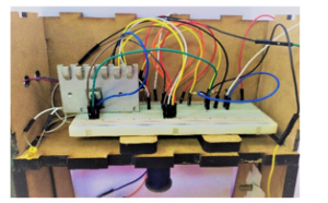
Figure 4: Electronic Circuit of the Levitation System.
A TRIAC heat-sink was placed because it is the electronic component through which all the electric force will pass and tends to heat up, and be prone to get worse.
During the implementation of the magnetic levitation system, tapes were used to hold the red laser pointer and the LDR, being a manual calibration, many tests had to be done to keep the metal objects levitating. These electronic devices had to be correctly placed one in front of the other to maintain the optimal current consumption, achieving with this precision to visualize the phenomenon.
6. Results
After assembling all the components explained above, it will simulate if the system is capable of levitating metal objects, and if it is strong enough to levitate heavy metal objects. Figure 5 shows two images where in the first one, it is seen that a coin is levitating and in the second image, the reader can appreciate a levitating screw, implying that it not only serves for objects of lesser weight such as currency but also with a bit considerable weights like a screw.

Figure 5: Magnetic Levitation System by Attraction (a) Levitation of a Coin (b) Levitation of a Screw.
It should be noted that for the levitation of metallic objects to work, the red light laser has to be in a small fraction in the photoresistor because there must be a voltage and current consumption by the coil to create a magnetic field capable of maintaining levitating to the metal object and it remains in balance.
The voltage variation was observed in the Voltage Source because when the metallic object is levitating as a result of the electromagnetic field generated by the coil, there was a higher current consumption; Figure 6 shows the use of a Voltage Source for the operation of the circuit to verify its variation.
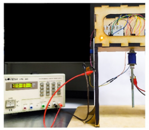
Figure 6: Response assembled prototype of a magnetic levitator system.
In addition, it was tried to verify the current flow that was going through the coil at that time, because it was wanted to know the variation that the signal presented in the coil at the time when it was with a metallic object levitating and when there was no metallic object in its area of operation. Because of this with the help of an electronic oscilloscope and probes, it was connected in the coil to know its electrical variation. As shown in Figure 7 (a) is the flow signal current when the coil was at rest, i.e. when there is no metal object in the magnetic field. Figure 7 (b) shows a square signal. This signal is when the coil has a metallic object in the operation area of levitation, but when the object moves away from the operation area of the coil then the square wave period increases until finally obtain an amorphous signal as the first one shown.
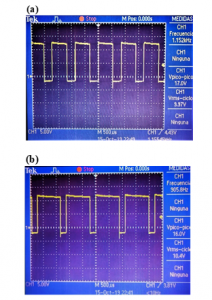
Figure 7: Signal of the Electric Flow of the Coil (a) Levitation of a Coin (b) Levitation of a Screw.
These signals, shown in Figure 7, show that the coil can reach stability when it has a metallic object levitating, in addition the period it presents is due to the fact that it is constantly charged and discharged from current.
7. Discussion
- To prevent the coil from overheating or reaching very high temperatures, many research studies indicate that the coil could be reinforced in the number of turns and the thickness of the coil so that it can dissipate heat, therefore, the circuit should also withstand more current because the coil will require.
- The implementation of the Magnetic Levitation System was tested after the design and construction of the structure because the positioning of all the elements was required for operation, prior to operation the level of power of the magnetic field was tested to attract metallic objects and control system presented by the red-light pointer and the LDR.
- The research work presents the implementation of a magnetic levitator based on the use of basic electronic components, it means that they are components known by students of first engineering cycles, thus enhancing the visualization of the phenomenon, disagreeing with the research work [10], where They use an ARDUINO for the implementation of a magnetic levitator, which is another implementation option but requires knowledge of programming languages for an educational environment, where students cannot visualize in detail the construction and location of each electronic component.
- The LDR electronic device is very sensitive to ambient light, that is why a previous calibration is required that covers the ambient light and can only receive the intensity of the red laser light, many investigations work on the design and implementation for that reason. A magnetic levitator indicates that the use of the infrared sensor is the best option.
- This research work, not only raises an educational-visual levitator of physical phenomena but also has the idea of future research, such as the union of two types of levitators such as repulsion and suspension. The subject of study of the magnetic fields is broad and very versatile, so we wonder what would happen if two types of levitators were joined, what characteristics these forces would have and how the levitating would object react as mention in [11], where they implemented a repulsion and suspension levitator with an analog regulator, but it must be with more knowledge in regulator and power electronic, it does not have educational focus but it has phenomenon visualization focus.
- Calibration complications arose because the red laser pointer and LDR must be correctly aligned, this calibration error and in addition to trial and error, generated vibrations, oscillations and even the malfunction of the magnetic levitation system. Calibration was manual because our main topic is to present this research work in the educational field for students to prove that with electronic circuits, magnetic fields and forces can be generated that allow the levitation of an object.
- The research team is sure that it will be of great use to take this device to schools or universities, as a study and inspiration, as it is a physical phenomenon that could be concluded and proved.
8. Conclusions
Creation has been made into the study of precision or control sensors, in this research work a red-light pointer and an LDR were used to control the system, based on these good results were obtained such as the levitation of metallic objects.
- The coil tends to heat due to the constant current consumption that is being induced, due to this it must be well placed at the base of the structure to prevent it from falling when it is in operation.
- The metallic object to remain levitated attracted by the magnetic field; must have a minimum presence in the intersection of the light sensor and the LDR so that it remains at a static point of levitation and current consumption by the circuit and the coil.
Conflict of Interest
The authors declare no conflict of interest.
- M. R. Khan, A. Raj, M. M. Hossain, S. Kumar, and A. Sharma, Distribution of electromagnetic field and pressure of single-turn circular coil for magnetic pulse welding using FEM. Singapore; New York: Springer, 2019.
- B. Meneses-Claudio, Z. Torres Santos, and A. Roman Gonzalez, “Study and design of a Magnetic Levitator System” International Journal of Advanced Computer Science and Applications, 10(5), 426-430, 2019. http://doi.org/10.14569/IJACSA.2019.0100553
- P. Rojas, R. Andrade, and J. Saavedra, La Reforma del Sistema Universitario Peruano: Internacionalización, avance, retos y oportunidades. Perú; Lima: British Council, 2016.
- G. Moreano, A. Darcourt, W. Hernández, and S. Ramos, Competencia científica e interés en carreras de Ciencia y Tecnología según PISA 2015. Perú; Lima: MINEDU, 2019.
- M. Pérez de Landazábal and P. Varela Nieto, Oersted and Ampère: origins of electromagnetism. España; Madrid: Nivola, 2001.
- J. P. Borrás, “Diseño, estudio y contrucción de un levitador magnético con Arduino”, Bachelor Thesis, Escuela Superior de Ingeniería Industrial, Universitat Politècnica de Catalunya, 2016.
- L. E Venghi, G. N. Gonzalez, and F. M. Serra, “Implementation and control of a magnetic levitation system,” IEEE Latin America Transactions, 14(6), 2651-2656, 2016. https://doi.org/10.1109/TLA.2016.7555233
- G. A. Marín and J. A. Garzón, Construcción de una plataforma de levitación electromagnética utilizando sensores infrarrojos, Ph. D. Thesis, Facultad de Tecnologías Eléctrica, Universidad Tecnológica de Pereira, 2015.
- S. Folea, C. I. Muresan, R. De Keyser, and C. Ionescu, “Theoretical Analysis and Experimental Validation of a Simplified Fractional Order Controller for a Magnetic Levitation System,” IEEE Transactions on control systems technology, 24(2), 1-7, 2015. https://doi.org/10.1109/TCST.2015.2446496
- J.P. Borràs Marne, “Diseño, estudio y contrucción de un levitador magnético con Arduino,” Escola Tècnica Superior d’Enginyeria Industrial de Barcelona – Grau En Enginyeria En Tecnologies Industrials, 2016.
- J.A. Ortega Díaz, “Diseño y construcción de un sistema de levitación magnética gobernado por un regulador analógico,” Escola d’Enginyeria de Barcelona Est – Grau en Enginyeria Electrònica Industrial i Automàtica, 2018.