Article

Accuracy Assessment of Direct Georeferencing for Photogrammetric Applications Based on UAS-GNSS for High Andean Urban Environments

by
Rolando Salas López
1,
Renzo E. Terrones Murga
1,2,
Jhonsy O. Silva-López
1,*,
Nilton B. Rojas-Briceño
1,3,
Darwin Gómez Fernández
1,
Manuel Oliva-Cruz
1 and
Yuri Taddia
4
1
Instituto de Investigación para el Desarrollo Sustentable de Ceja de Selva, Universidad Nacional Toribio Rodríguez de Mendoza, Chachapoyas 01001, Peru
2
Lidar Peru Sociedad Anónima Cerrada|Lidar Peru, Av. Alfredo Benavides Nro. 1944, Lima 15047, Peru
3
Instituto de Investigación en Ingeniería Ambiental, Facultad de Ingeniería Civil y Ambiental, Universidad Nacional Toribio Rodríguez de Mendoza de Amazonas, Chachapoyas 01001, Peru
4
Engineering Department, University of Ferrara, Via Saragat 1, 44122 Ferrara, Italy
*
Author to whom correspondence should be addressed.
Drones 2022, 6(12), 388; https://doi.org/10.3390/drones6120388
Submission received: 9 October 2022 / Revised: 27 November 2022 / Accepted: 28 November 2022 / Published: 30 November 2022
(This article belongs to the Special Issue Unconventional Drone-Based Surveying)

Abstract

:
Unmanned Aircraft Systems (UAS) are used in a variety of applications with the aim of mapping detailed surfaces from the air. Despite the high level of map automation achieved today, there are still challenges in the accuracy of georeferencing that can limit both the speed and the efficiency in mapping urban areas. However, the integration of topographic grade Global Navigation Satellite System (GNSS) receivers on UAS has improved this phase, leading to a reach of up to a centimeter-level accuracy. It is therefore necessary to adopt direct georeferencing (DG), real-time kinematic positioning (RTK)/post-processed kinematic (PPK) approaches in order to largely automate the photogrammetric flow. This work analyses the positional accuracy using Ground Control Points (GCP) and the repeatability and reproducibility of photogrammetric products (Digital Surface Model and ortho-mosaic) of a commercial multi-rotor system equipped with a GNSS receiver in an urban environment with a DG approach. It was demonstrated that DG is a viable solution for mapping urban areas. Indeed, PPK with at least 1 GCP considerably improves the RMSE (x: 0.039 m, y: 0.012 m, and z: 0.034 m), allowing for a reliable 1:500 scale urban mapping in less time when compared to conventional topographic surveys.

1. Introduction

Originally, Unmanned Aircraft Systems (UAS) were developed mainly for military purposes and applications such as unmanned inspection, surveillance, reconnaissance, and mapping of hostile areas [1]. The first civil UAS experience in geomatics took place in the 1990s. Nowadays, UAS represent a common platform for photogrammetric data acquisition [2]. Accordingly, UAS is an alternative for mapping and to perform a spatial analysis of the territory [3,4]. This data collection technology offers similar quality and reliability results when compared to conventional topography, which requires higher costs for its application instead [5]. Therefore, the use of UAS is more economically profitable than other technologies such as the use of Global Navigation Satellite System (GNSS) receivers [6], Terrestrial Laser Scanning (TLS) [7], Light Detection and Ranging (LiDAR) [8] and conventional aerial photogrammetry [9].
Images acquired by UAS offer useful information for archaeological documentation [10], geological and geomorphological surveys and monitoring [11,12,13], urban modeling [14,15,16,17], emergency assessment [18], and engineering applications [19,20]. Based on the use of the structure-from-motion (SfM) algorithm [21], which could replace conventional surveying methods, centimeter accuracies can be obtained according to the scale of study [22,23]. In order to achieve such a level of accuracy in the mapping of urban areas using UAS, a high overlap between captured images is required [24,25]. Afterwards, detailed photogrammetric models (Point Cloud, Digital Elevation Model, Orthophoto) are obtained by indirect or direct georeferencing [26].
Indirect georeferencing (IG) of these models is based on extensive field deployment, survey deployment, and ground control point (GCP) reconnaissance. The latter are subsequently recognized on the images within the photogrammetric software in the lab/office [27,28,29]. On the other hand, direct georeferencing (DG) replaces GCPs with aerial control by GNSS-assisted Bundle Block Adjustment (BBA) using Automatic Aerial Triangulation (AAT), which is one of the most widely used techniques in aerial photogrammetry [30,31]. In AAT, the coordinates of the camera stations are measured by an integrated GNSS receiver at each exposure time and are introduced as constraints in the BBA adjustment [32,33], or they are used to calculate the transformation of the arbitrary SfM reference to the mapping system accurately [28].
However, the accuracy obtained is influenced by the type of data processing, and there are three common configurations for geotagging photographs in an SfM workflow. (i) On-board position calculation: photo positions are based on the location of the UAS and recorded as an Exchangeable Image File (Exif) data; (ii) Post Processed Kinematic (PPK): photo positions are calculated after flight based on records from the mobile (UAS) and a GNSS base station; and (iii) Real Time Kinematic (RTK): photo positions are calculated in real-time, with corrections sent to the mobile directly from the base station [34]. The base station can be local or in special cases, a correction can be sent from a co-commercial base station via Networked Transport of RTCM via Internet Protocol (NTRIP protocol) to the remote controller [22,35]. In this context, guaranteeing the recording and storing of coordinates in a known place for the PPK [36] and RTK [26] configuration depends largely on the location of the base station and mobile, which must share an appropriate geometrical configuration of satellites and carrier phase [37].
In DG, no GCPs collected with external GNSS are required to process aerial photographs, thus the workflow becomes less time-consuming and costly. Nevertheless, there is a need to mitigate UAS camera positioning errors for complex geometry scenarios, such as urban environments or linear mapping (urbanized corridors, runways, etc.) [38]. This can be done using a GNSS navigation/quality inertial navigation system (INS), thus obtaining a high accuracy, but at an increased cost for UAS [23,39]. In recent years, variations of such techniques have been developed to address the specific peculiarities of UAS-based aerial photogrammetry, including relative position/orientation control [2,40], raw observation, and multi-sensor adjustment [41]. However, the use of GCPs is important to establish adequate topographic control [41,42,43].
In that context, the Phantom 4 RTK UAS (DJI-P4RTK), having an integrated multi-frequency GNSS receiver, allows for the performance of either a PPK, RTK, or NTRIP DG approach [44,45]. In addition, P4RTK contains a non-metric camera, with limitations on identifying appropriate Interior Orientation Parameters (IOP) along with the package setting. However, this could be overcome by using at least one GCP or one chamber pre-calibration [37,42,46]. Furthermore, having a GNSS receiver allows for storing raw data that can be used for further evaluations. Accordingly, the UAS allows one to perform an indirect orientation using GCP, as well as the direct orientation of the measured image positions (external orientation—EO). Due to this, in this study, the combination of both (GCP and EO), known as integrated orientation was used, which has shown better accuracies [45].
Integrated guidance for UAS has been used both in coastal mapping [47] and in rural and urban mapping [48]. There is no current knowledge about the variants of the data capture mentioned in PPK and RTK [49], particularly for urban environments with complex physiography such as the city of Chachapoyas (narrow access roads, typical of colonial-era cities in Peru). Therefore, this research aims to analyze the accuracy of the photogrammetric models (DSM and ortho-mosaic) based on the accuracy standards set by the American Society for Photogrammetry and Remote Sensing (ASPRS) [50,51,52]. For this purpose, three types of flights are analyzed using the RTK and PPK approach acquired by the UAS, which are combined with a set of GCPs (1, 5, and 10) to create 27 photogrammetric projects. This study identifies the most suitable UAS data acquisition and processing method for mapping an urban area. It also has the potential for replicability in similar areas with rugged physiography and multiple colonial buildings, or other similar scenarios.

2. Materials and Methods
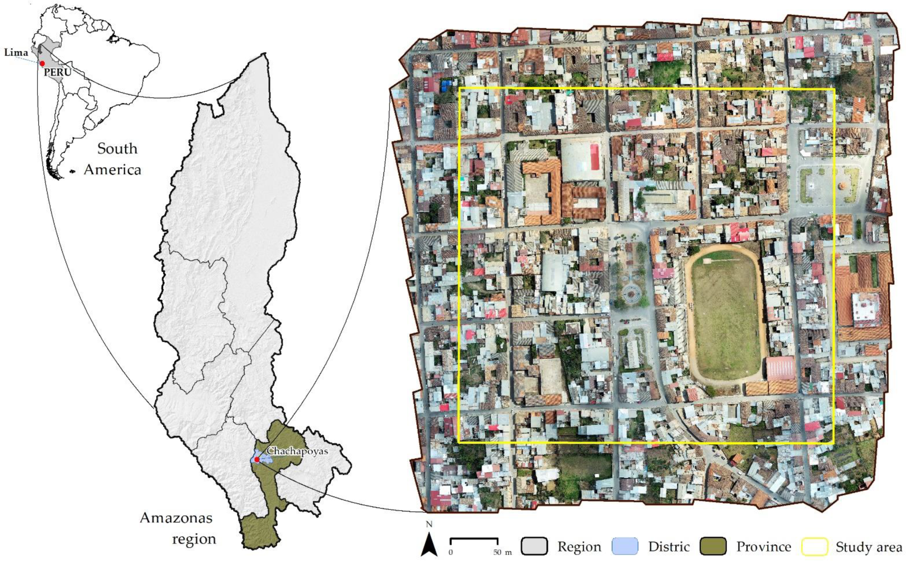
2.1. Study Area

The city of Chachapoyas (6°13′45.84″ S; 77°52′20.47″ W), which is the capital of the department of Amazonas, is located in the north-eastern Peruvian Andes at 2483 m above mean sea level (m.a.s.l.). The city is 1200 km far away from Lima, the capital of Peru (Figure 1). The climate varies from temperate to moderately rainy, with a cumulative annual rainfall of 777.8 mm and maximum and minimum temperatures (period 1960–1991) of 19.8 °C and 9.2 °C, respectively. It has a marked climatic seasonality with an alternating rainy season from November to April, and a dry season from May to October [53,54]. The urban area of the city of Chachapoyas covers 2239.35 ha, of which 15 ha belonging to the La Laguna neighborhood was mapped with six cadastral blocks, consisting of multiple colonial buildings and narrow, steeply sloping streets [54].

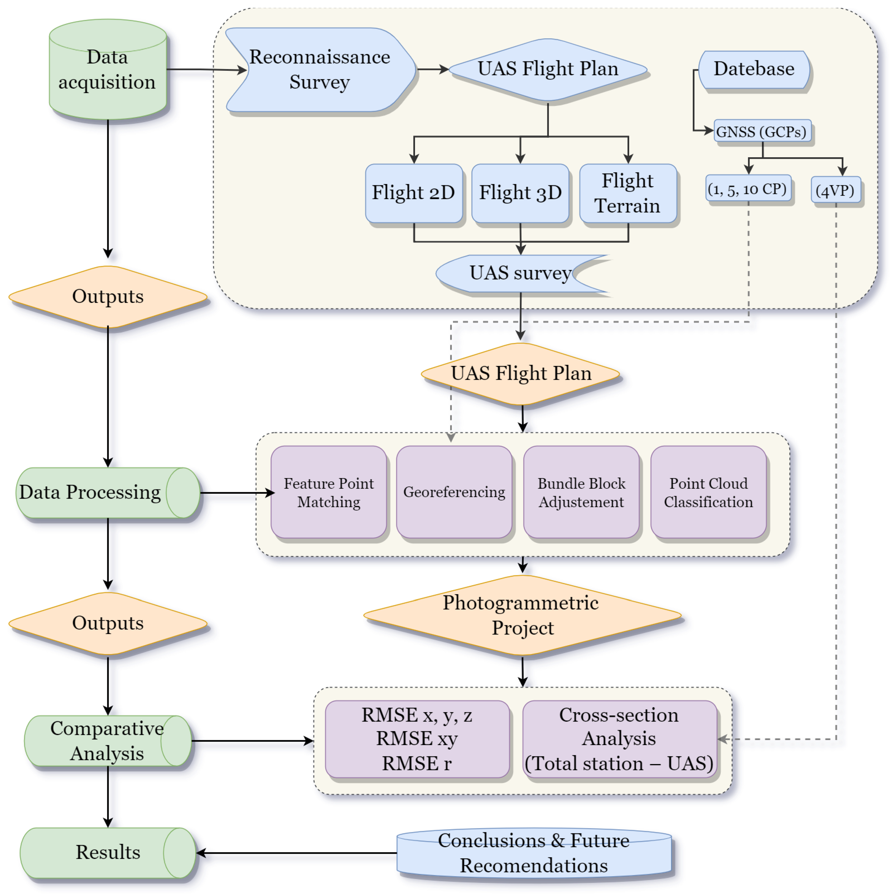
2.2. Data Acquisition
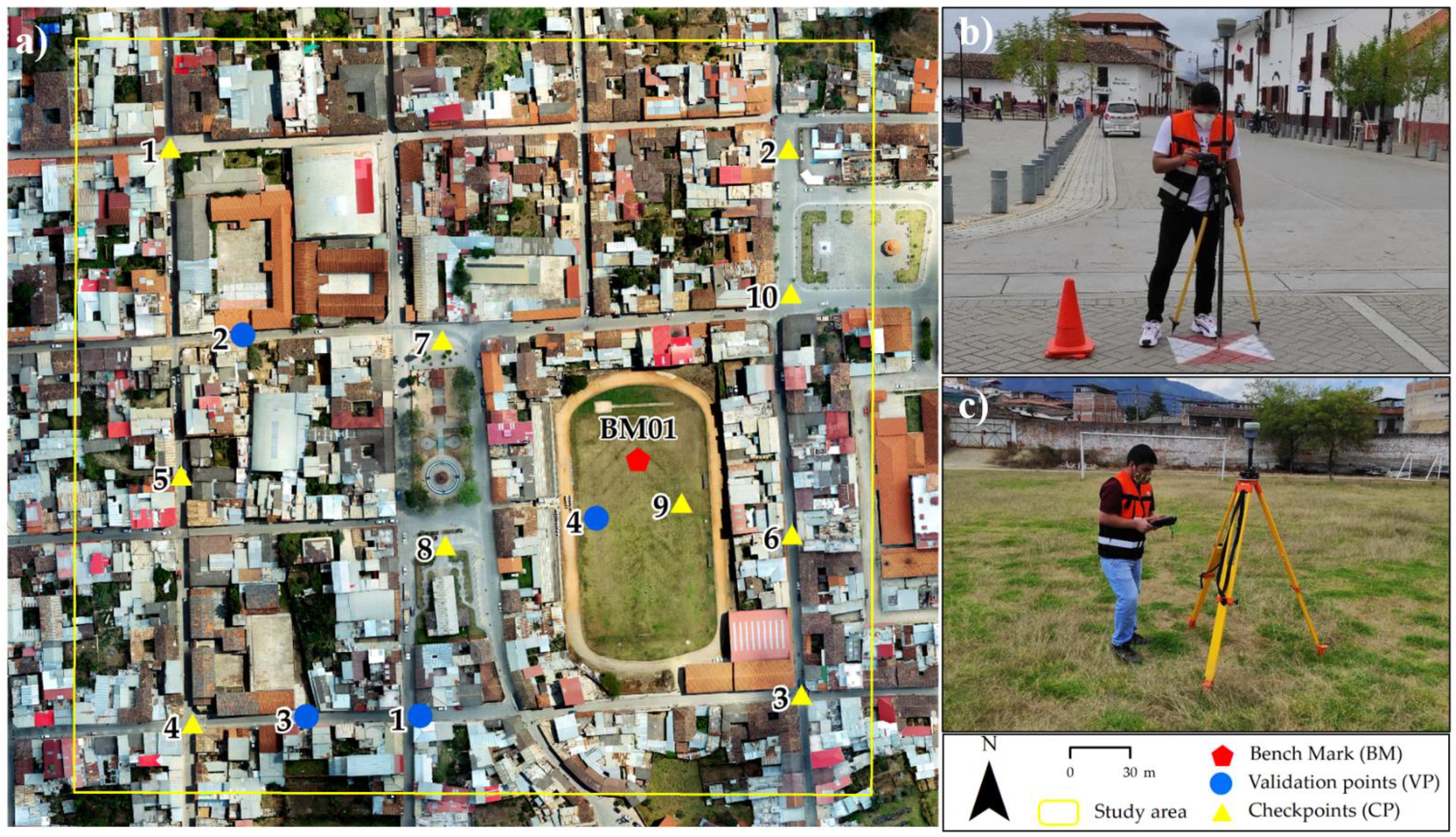
2.2.1. GNSS Survey

In this work, 10 GCPs and 4 Validation Points (VPs) were established. The GCPs and VPs were represented as square-shaped marks of 0.533 m in size (Figure 2a). The three-dimensional coordinates of these targets were collected with a Trimble R10 GNSS receiver operated in PPK mode (Figure 2b). The base station was established at a geodetic point of order C [55] with a record of 7 min and was calculated by a static survey, previously corrected with a geodetic pillar (AMA01) of the Peruvian National Geographic Institute (IGN) [55]. The metric coordinates of BM-01 (Bench Mark) were 18,2601.173 m E, 9,310,378.217 m N, and 2357.706 m.a.s.l. (Figure 2c). These horizontal coordinates refer to the Universal Transverse Mercator (UTM) Zone 18 South coordinate system, and the elevation refers to the MSL using the EGM08 geoid model. For PPK mode GCP measurements, these multi-frequency GNSS geodetic instruments have an accuracy specification set by the manufacturer of ±3 mm + 0.5 ppm horizontal RMS and ±5 mm + 1 ppm vertical RMS [56]. In particular, since the distance between the base station and the study area was approximately 260 m, the horizontal and vertical errors were 1 and 2 cm, respectively.

2.2.2. UAS Planning

Three types of flights were performed: grid (2D), double grid (3D), and terrain tracking, planned to use the GSRTK mobile application [45]. In addition, the altitude optimization option was used. This enabled the collection of oblique images (−45°) from the lower left corner to the center of the study area, except for the terrain-following flight type [45]. This “hybrid” data collection is useful for simulating the results of image acquisition in general [44]. These flights covered an approximate area of 15 ha with a Ground Sampling Distance (GSD) of 3.84 cm. A nadir position of the camera was established, except for the 3D flight (−60°) taking into account north-south flight lines, as well as an overlap of 80% longitudinally and 75% laterally, and an average flight height of 140 m. Each type of flight was executed using three positioning solutions (Table 1). This resulted in the execution of six photogrammetric flights over the study area. For RTK, three configurations were considered, in which CP (1, 3, and 5) were used for the type of 2D flight, 3D flight and ground tracking. Similarly, the same was applied to PPK1 and PPK2, resulting in a total of 27 photogrammetric projects.

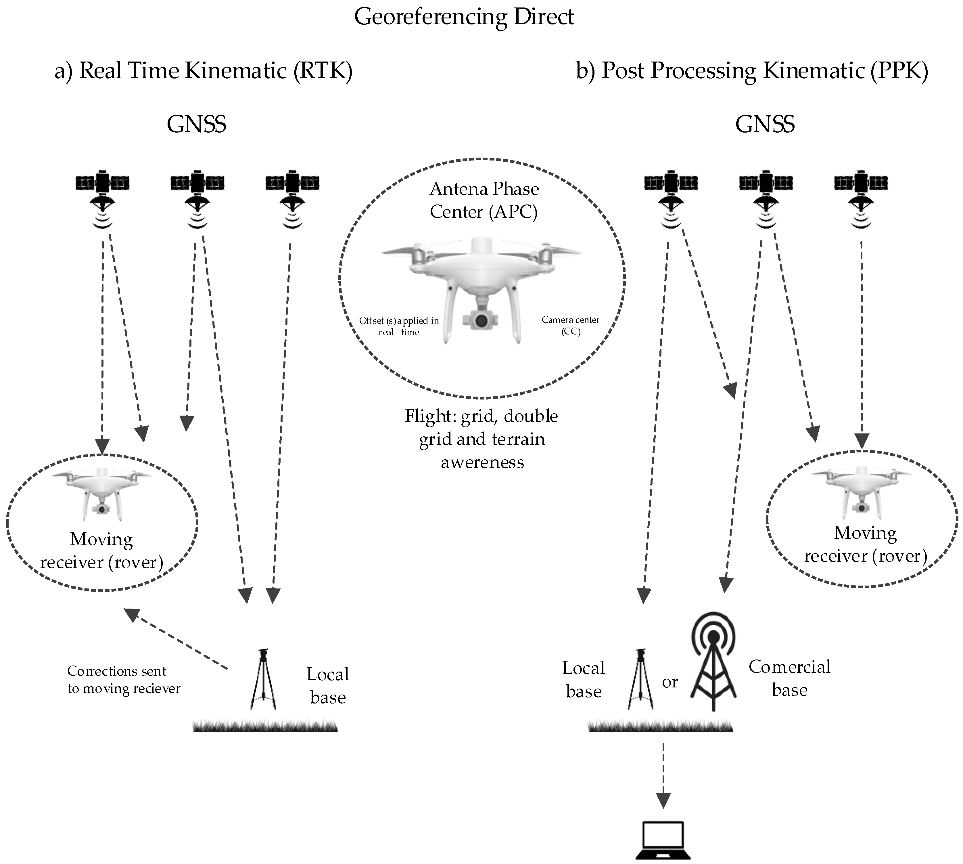
2.3. Positioning Configurations Adopted during Flight Tests

2.3.1. UAS-RTK Surveying

An RTK approach was performed (Figure 3a), with the specifications given by Teppati et al. [49]. The DJI GNSS base station DRTK2 [57] was used as a positioning solution, which transmits real-time corrections to improve the positioning accuracy of the UAS located at any point with known or unknown coordinates [34]. For this work, we adopted the solution that requires the use of a point of known coordinates (BM-01): the GNSS base station was placed in the central part of the study area (Figure 2c), enabling reconstruction of the orientation and the displacement of the camera concerning the APC (Antenna Phase Center) for the PPK approach.

2.3.2. UAS-PPK Surveying

For the PPK approach (Figure 3b), which is the correction of the UAS positions recorded by the GNSS receiver during flight and the estimation of the camera positions after the data acquisition phase, a post-process is required. Here, the Trimble R10 GNSS receiver with a known coordinate (BM-01) storing data in static mode at one second in the PPK1 configuration (Table 1) was used as a base. Similarly, the data from the AMA01 geodetic pillar (recorded every 5 s) was used in the PPK2 configuration. Consequently, in order to process the data, it is necessary to use either a self-built solution [47] or free third-party software [58], or alternatively commercial software [59]. For this work, PPK processing was performed using RED toolbox, which performed geotagging with fixed solutions for all images. RED toolbox, for P4RTK and other DJI products, automatically calculates the lever arm from the information stored in the UAS files, compared to the free RTKLIB software used by Teppati et al. [49].

2.4. Photogrammetric Processing of the Acquired Data

The photogrammetric processing flow (Figure 4) consists of matching waypoints from the UAS images. These images were automatically calibrated based on EXIF information for tie point generation. The calibrated images were georeferenced using an integrated orientation to generate a dense 3D point cloud, and to subsequently obtain the DSM and ortho-mosaic. Image georeferencing is the first step in obtaining photogrammetric products (ortho-mosaics, DSM, DTM, and contour lines) and represents the prerequisite for their metric exploitation [60].

2.5. Comparative Analysis

2.5.1. Accuracy Assessment

In order to perform the assessment of both horizontal (ortho-mosaic) and vertical (DSM) accuracy, the ASPRS guide [49] was used as a reference. For the altitude coordinate (Z), the location of the vertical control points should be surveyed on flat open terrain or with uniform slopes and slopes ≤10%. According to the guide, the vertical non-vegetation accuracy (NVA) at the 95% confidence level in unvegetated terrain is approximated by multiplying the vertical accuracy class accuracy values (or RMSEz) by 1.96.
The first method to assess accuracy is the root mean square of the quadratic differences between the reconstructed model and the surveyed GCP coordinates, known as the root mean square error (RMSE) [61]. The horizontal (x and y) and vertical (z) positional accuracies were determined for the photogrammetric projects from the GCP coordinates, specifically with the validation points (VPs) within Agisoft Metashape [60].
The RMSE values for the X, Y, Z, and r components are estimated as shown in Equations (1)–(5). Where the sub-indices oi and GNSSi of X, Y, and Z represent the coordinates estimated by the ortho-mosaic and measured by the GNSS receiver, respectively.
RMSE X = ±   i = 1 n ( X oi X GNSSi ) 2 n
RMSE Y = ±   i = 1 n ( Y oi Y GNSSi ) 2 n
R M S E Z = ±   i = 1 n ( Z oi Z GNSSi ) 2 n
R M S E X Y = ±   RMSE X 2 + RMSE Y 2
R M S E r = ±   RMSE X 2 + RMSE Y 2 + RMSE z 2

2.5.2. Cross-Section Analysis

In urban mapping, assessing height differences through cross-sectional profiles is an important issue [62,63]. For this reason, a profile was extracted from the DSMs, to be compared with the cross-sectional profile surveyed in the field by a total station (Trimble M5 1’).
The DSM resolution of the 27 photogrammetric projects ranged from 0.06 to 0.105 m. Thereafter, all DSMs were re-sampled using the nearest neighbor technique to a resolution of 0.105 m, to make them compatible and consistent for the comparative analysis of transverse profiles. To generate the cross-sectional profile, a 40 m line was drawn on the ortho-mosaic in the central part of the study area; the altimetric data was hence collected in the field using the total station with a step of 0.10 m, monitoring the changes in altitude.
Notably, the cross-section has been selected in the region where the 2D, 3D, and Terrain flight plans overlap to compare the 27 DSMs generated in this work, with the data collected from the cross-section obtained by the total station during the survey operations.

3. Results

3.1. Geometric Accuracy of Aerial Photographic Mosaics
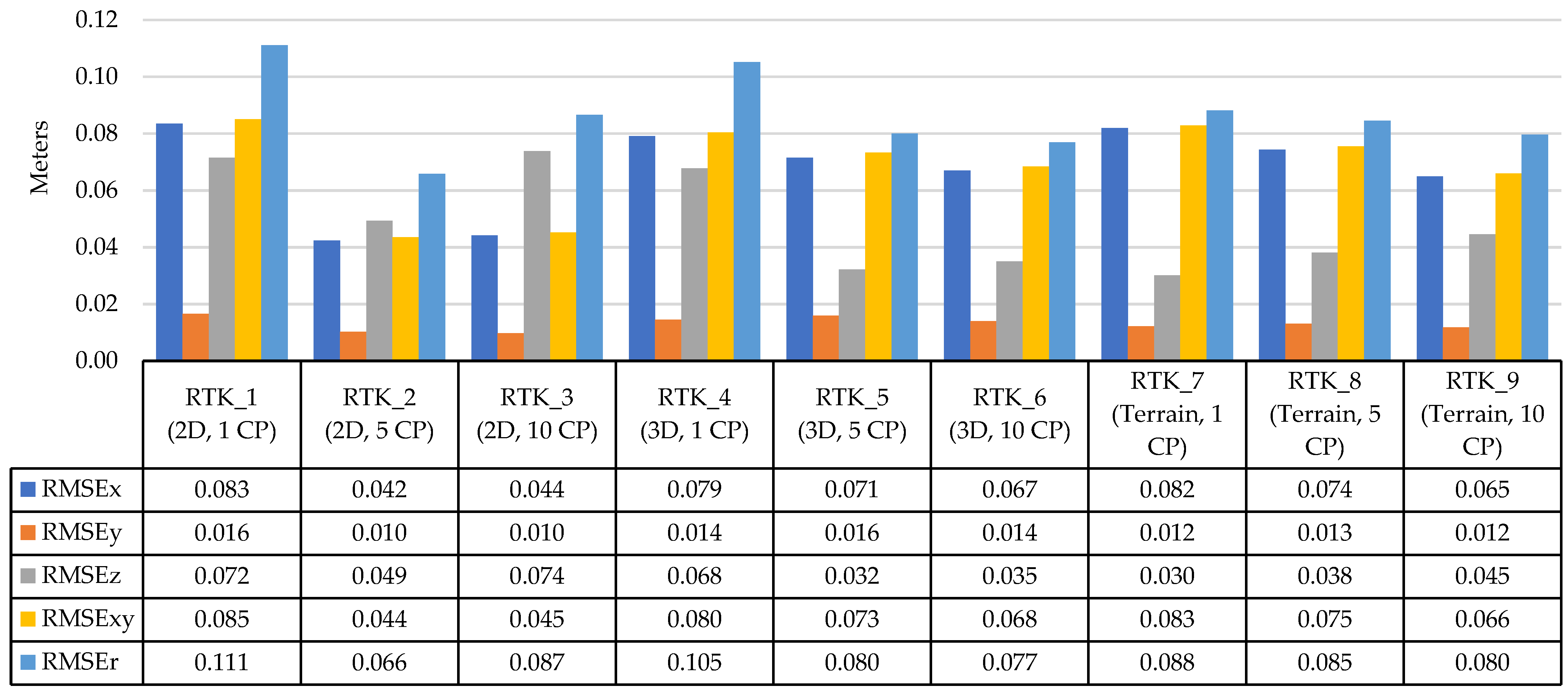
3.1.1. RTK Accuracy

RMSE was calculated based on the VP (04) for the RTK photogrammetric projects (Figure 5). Using the real-time correction of the GNSS receiver base DRTK2 linked to a known point BM-01 (Figure 2), different solutions were tested according to the type of images acquired in the field (2D, 3D, and terrain) and the number of GCPs used for the block orientation (1, 5 and 10), obtaining 9 UAS photogrammetric projects.
All of the 9 configurations present an RMSEr between 0.066 m and 0.111 m computed through the VPs. The RTK4 configuration has the highest RMSEr value, whereas the RTK2 configuration shows the lowest value (0.06 m). Indeed, using 5 GCPs reduces the precession by 0.05 m compared to RTK_1 with 10 GCPs, reducing the fieldwork by surveying GCPs. According to ASPRS, the RTK_2 configuration with a GSD of 3.84 cm/px belongs to Class II, which allows one to perform mapping at a scale of 1/500.
The VPs distributed within the urban area have an RMSEz value ranging from 0.030 m to 0.074 m, with the RTK_7 Terrain mode configuration with 1 GCP having the best accuracy, meaning that the non-vegetated vertical accuracy (NVA) values are equal to RMSEz (58.8 mm). This dataset was tested to meet ASPRS positional accuracy standards for a vertical accuracy class of 10 cm. The actual accuracy of the NVA was found to be 7 cm, which is equivalent to +/− 15 cm at a 95% confidence level. This is considered acceptable for urban mapping applications.

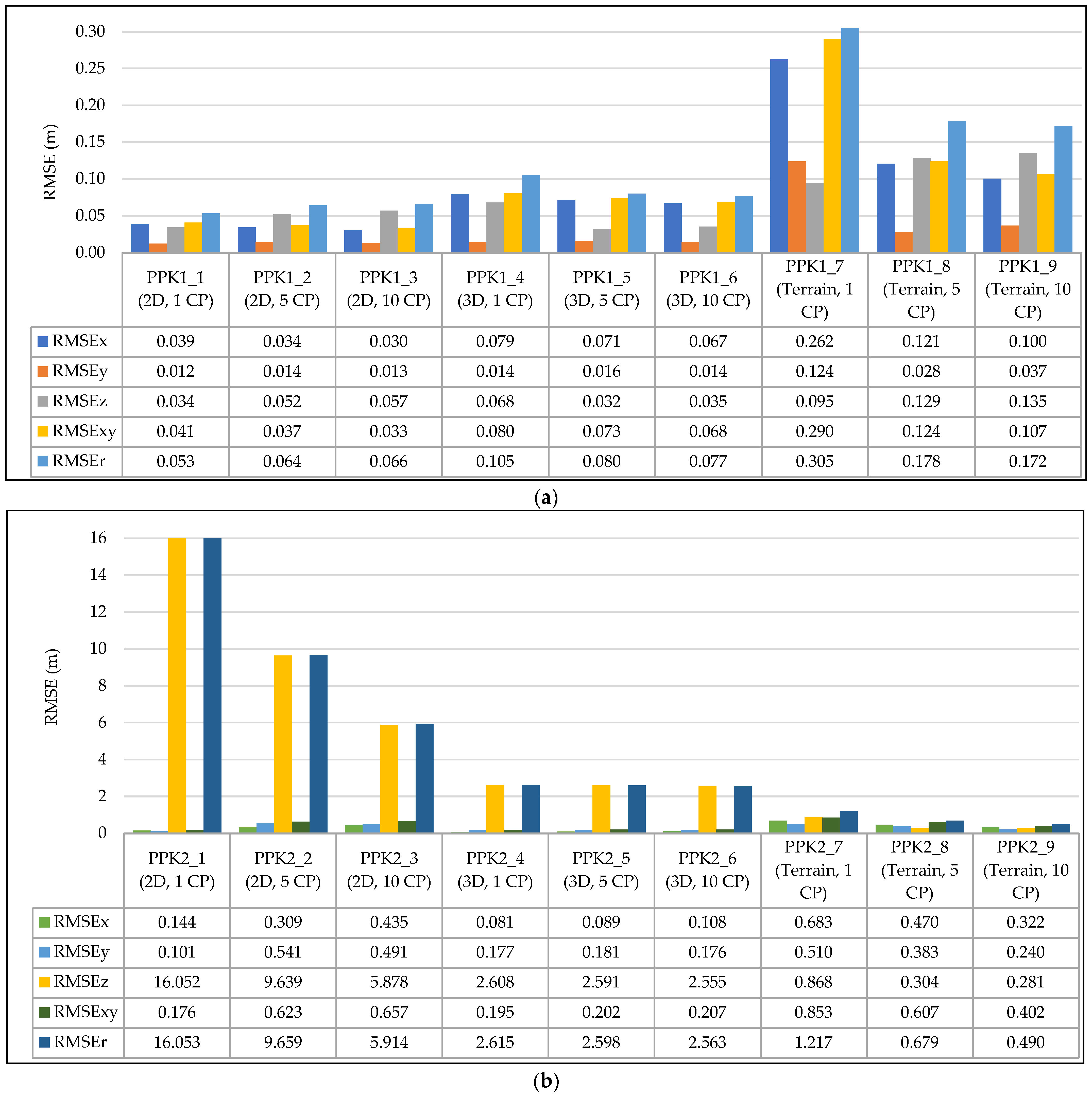
3.1.2. PPK1 and PPK2 Accuracy
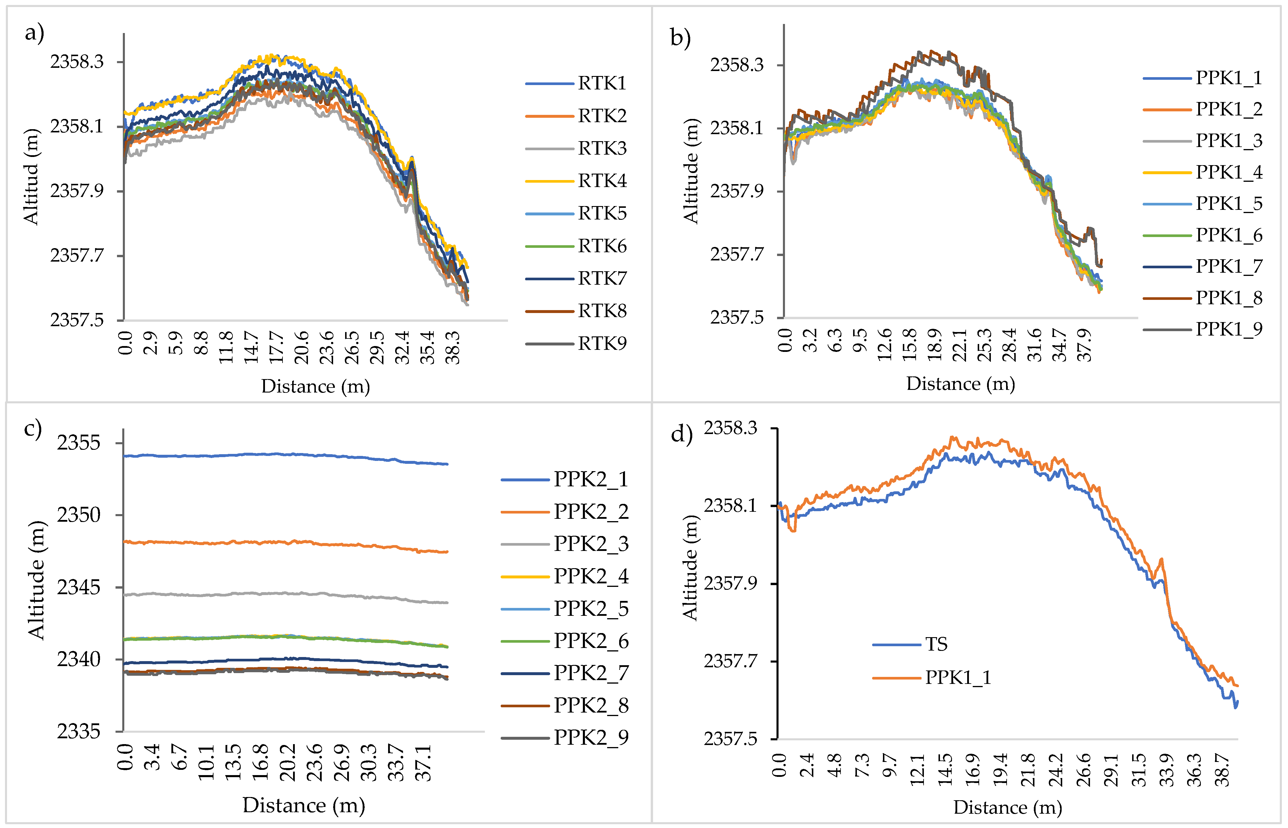
Both the results of the PPK1 and PPK2 approaches consist of 9 photogrammetric projects, from PPK1_1 to PPK1_9 (Figure 6a) and from PPK2_1 to PPK2_9 (Figure 6b), respectively. Figure 6 shows the RMSEr of the VPs for the different configurations, the error for the x, y, z, xy components, and the total error.
The best RMSEr of the PPK1 approach was found for the PPK1_1 configuration (2D flight with 01 GCPs), with an overall accuracy of 0.053 m. For the PPK2 approach, the best RMSEr was obtained using the PPK2_9 configuration (0.490 m), which consisted of a ground flight mode with 10 GCPs. The latter is a high value when compared to the RTK and PPK1 approaches.
Similarly, the VP within the urban area have an RMSEz value of 0.034 (PPK1_1) m and 0.281 (PPK2_9) m. Here, the PPK1_1 GCP configuration obtained the best accuracy results, which means that the NVA = RMSEz × 1.96 = 63 mm. This dataset was tested to meet ASPRS positional accuracy standards for a vertical accuracy class of 10 cm. The actual accuracy of the NVA was found to be 5 cm, which is equivalent to +/− 10 cm at a 95% confidence level, and is therefore considered acceptable for urban cadastral applications.

3.2. Cross-Section

Regarding the cross-section of the DSM (Figure 7), it can be noted that, in the RTK approach (Figure 7a), on average, all the configurations present small variations of 0.05 m between the profiles extracted from the model and the ones surveyed by the total station (TS). On the contrary, the PPK approach (Figure 7b) presents similarities in altitude in all of the profiles except for PPK_8 and PPK_9, which have a difference of 0.10 m in the central part of the graph.
In the case of the PPK approach (Figure 7c), this presents a very high-altitude bias versus the TS plot of approximately 2–15 m along the cross-section. On the other hand, the configurations that integrated some oblique images in the nadiral dataset (PPK_1, PPK_5, PPK_6, RTK5, RTK6) produced profiles that generally presented less altitude bias, considering also a vertical level of uncertainty of a few centimeters.
Figure 7d shows the most accurate terrain profile concerning the data collected by the total station. Overall, the PPK_1 2D flight mode configuration with 1 GCP seems to have the highest accuracy.

4. Discussion

For the 27 photogrammetric projects analyzed in this study, using RTK, PPK1, and PPK2 approaches, a 3D accuracy of 0.066 m, 0.053 m, and 0.49 m was obtained, respectively. Such values conform to the APRSS [50] mapping standard of a nominal map scale of 1:500. For all solutions, an integrated orientation approach (EO + GCPs) was adopted, since this approach presents better results, as discussed by Przybilla [46]. However, to adopt the best solution for a direct georeferencing (GI) approach, specific guidelines must be followed, such as collecting GCPs in situ for block adjustment (at least 01) and flying with a minimum overlap of 80% in urban areas and within a range of 80 to 120 m in altitude above ground level [36].
In regards to the flight planning, when covering the area to be mapped with two flights or more, these should be connected to a base station by RTK or NTRIP, as it reinforces the acquisition geometry improving the estimation of internal parameters of the IOP. This was not the case for the PPK2 approach, which had an offset between flight plans, decreasing the overlap of the photo capture and resulting in a considerable increase of the RMSEr 0.437 m to PPK1 (0.53 m). This is due to the desynchronization of the collected data [23]. In Peru, the IGN’s commercial GNSS bases are in the process of being modernized so that they can collect static data at 1Hz [64], which would significantly reduce the RMSRr of photogrammetric projects.
In addition, for the PPK1 and PPK2 approach in the ground-based mode, it has a high RMSE (33 times more) because a global DEM (90 m) was used to map the area, which resulted in a risky flight and low overlap of photos. Therefore, to perform a flight with proper terrain tracking, a high-resolution DEM with a topographic precision is necessary [65].
The RTK approach presents difficulties because there is a need to have at least one known coordinate point in the area of interest, as well as a real-time signal connection at all times from the DRTK2–P4RTK to obtain optimal results. The signal in urban areas tends to be lost, causing a poor photograph geotagging accuracy due to signal structures and interferences by communication antennas [46]. Therefore, DJI implemented the RTK FIX option, which allows keeping the connection fixed for up to 10 min [45]. That is, the longer P4RTK and D-RKT2 remain unconnected (10 min max.), the more the RTK signal drops.
This caused the RTK approach using the GNSS D-RTK2 GNSS base, specifically the RTK_2 configuration, to have a slightly higher RMSEr (0.066 m) than the PPK1_1 approach (0.053 m). Besides, the accuracy of the reference point coordinates can directly influence the accuracy of the coordinates stored in the geotag of the acquired images [61].
Practical experience also showed that the PPK approach [34,36,46,47,49], specifically PPK1, is preferable to RTK technology [22,46,62,66] in an environment where frequent occlusion of satellite signals occurs due to the movement of the drone or its surrounding communication signals (e.g., radio signals, telephone lines, television, etc.). Although there is the option of using the PPK approach with the D-RTK2 GNSS receiver, it is not yet available as an official DJI solution to perform such post-processing of data derived from static mode acquisitions [45]. This makes it necessary to use a third-party GNSS base, increasing the costs of the photogrammetric survey. Furthermore, it is worth mentioning that there is the RTK approach via NTRIP using a local or commercial GNSS base receiver. The latter approach has been used in previous studies [34,59], but Peru currently lacks the NTRIP service, hence we have not used it for this study.
It was also demonstrated that the cross-sectional profiles of the PPK1 approach best match the profile obtained using the total station. This is of the utmost importance for the remodeling, construction, and design of roads in urban environments, leading to the convenience of this comparison [47,66].
Overall, the PPK1 approach led to the best 3D accuracy of the block orientation phase of the block using at least one GCP. It was demonstrated that using data derived from a GNSS receiver allows for a faster acquisition in the field, as well as lowering requirements in terms of deployment of instrumentation. For large-scale mapping purposes, it is strongly recommended to use a GNSS receiver within the surveyed area.
For future research and in similar study area conditions, it is recommended to perform camera calibration a priori, in order to evaluate whether the accuracy of the photogrammetric model is improved or not. This is because the DJI UAS cameras cannot be considered metric and stable cameras [46]. It is also recommended to use PPK approaches in NTRIP mode on a commercial basis. In addition, geo-tagging processing should be done with the use of free and paid software on a comparative basis.

5. Conclusions

Direct georeferencing was shown to be a viable solution for mapping urban areas with multiple colonial buildings and narrow streets. It was noted that the PPK1 approach is better than PPK2 and RTK. PPK1 errors are between 0.053 to 0.305 m, unlike PPK2 ranging from 0.49 to 16.053 m, the latter being about 33 times greater than PPK1. This was due to the temporary desynchronization of data stored in AMA01 (5Hz) and P4RTK (1Hz). In the case of the PPK1 (PPK1_1 to PPK1_6) approach, this method is slightly better than the RTK approach, presenting RMSEr 0.053 to 0.105 m and 0.066 to 0.111, respectively. This is because inside a city there is often an interference caused by telecommunications networks, which generate positioning errors in some cameras due to a signal loss.
In addition, if we consider the PPK1_1 approach in a 2D flight with at least 1 GCP, this kind of configuration significantly improves the RMSEz when compared to the use of 5 or 10 GCPs. The precision also improves horizontally, obtaining an RMSEr of 0.053 m, which allows for the development of urban cartography on a scale of 1:500.
Photogrammetry application is possible using UAS and applying the DG technique, in particular the PPK1 approach. Therefore, in the case of Peru, it is not recommended to use the PPK2 approach due to the desynchronization of the collected data, despite the use of different GCPs. Additionally, signage such as GCP recognition requires considerable effort in cartography with UAS, especially in complex terrain such as cities with multiple colonial buildings in which it is not possible to conduct an RTK study of GNSS. In this sense, we recommend a more in-depth analysis of the new UAS configurations with the GD approach to use GCPs to a lesser extent.

Author Contributions

Conceptualization, R.S.L., R.E.T.M. and N.B.R.-B.; Methodology, R.E.T.M. and J.O.S.-L.; Software, R.E.T.M. and J.O.S.-L.; Validation, R.E.T.M. and J.O.S.-L.; Formal analysis, R.E.T.M., J.O.S.-L., N.B.R.-B. and Y.T.; Investigation, R.S.L., J.O.S.-L. and D.G.F.; Resources, R.E.T.M. and M.O.-C.; Data curation, R.E.T.M., J.O.S.-L., D.G.F. and Y.T.; Writing—original draft, R.E.T.M. and J.O.S.-L.; Writing—review & editing, R.E.T.M. and N.B.R.-B.; Visualization, R.S.L. and D.G.F.; Supervision, R.S.L., N.B.R.-B., M.O.-C. and Y.T.; Project administration, R.S.L. and M.O.-C.; Funding acquisition, R.E.T.M. and N.B.R.-B. All authors have read and agreed to the published version of the manuscript.

Funding

This work was carried out with the support of the Public Investment Project GEOMÁTICA (CUI N° 2255626), executed by the Instituto de Investigación para el Desarrollo Sustentable de Ceja de Selva (INDES-CES) of the Universidad Nacional Toribio Rodríguez de Mendoza de Amazonas (UNTRM).

Data Availability Statement

The data used to support the findings of this study are available from the corresponding author upon request.

Acknowledgments

The authors acknowledge and appreciate the support of the Instituto de Investigación para el Desarrollo Sustentable de Ceja de Selva (INDES-CES) of the Universidad Nacional Toribio Rodríguez de Mendoza de Amazonas (UNTRM). We deeply thank Nilton Atalaya Marin and Jhon A. Zabaleta Santisteban for their technical and logistical assistance.

Conflicts of Interest

The authors declare no conflict of interest.

References

  1. Koslowski, R.; Schulzke, M. Drones along Borders: Border Security UAVs in the United States and the European Union. Int. Stud. Perspect. 2018, 19, 305–324. [Google Scholar] [CrossRef]
  2. Blázquez, M.; Colomina, I. Relative INS/GNSS aerial control in integrated sensor orientation: Models and performance. ISPRS J. Photogramm. Remote Sens. 2012, 67, 120–133. [Google Scholar] [CrossRef]
  3. Kerle, N.; Nex, F.; Gerke, M.; Duarte, D.; Vetrivel, A. UAV-Based Structural Damage Mapping: A Review. ISPRS Int. J. Geo-Inf. 2019, 9, 14. [Google Scholar] [CrossRef] [Green Version]
  4. Jiang, S.; Jiang, C.; Jiang, W. Efficient structure from motion for large-scale UAV images: A review and a comparison of SfM tools. ISPRS J. Photogramm. Remote Sens. 2020, 167, 230–251. [Google Scholar] [CrossRef]
  5. Grubesic, T.H.; Nelson, J.R. UAVs and Urban Spatial Analysis; Springer: Cham, Switzerland, 2020. [Google Scholar]
  6. Mozas-Calvache, A.T.; Pérez-García, J.L. Analysis and Comparison of Lines Obtained from GNSS and UAV for Large-Scale Maps. J. Surv. Eng. 2017, 143, 04016028. [Google Scholar] [CrossRef]
  7. Roberts, J.; Koeser, A.; Abd-Elrahman, A.; Wilkinson, B.; Hansen, G.; Landry, S.; Perez, A. Mobile Terrestrial Photogrammetry for Street Tree Mapping and Measurements. Forests 2019, 10, 701. [Google Scholar] [CrossRef] [Green Version]
  8. Xu, S.; Vosselman, G.; Elberink, S.O. Multiple-entity based classification of airborne laser scanning data in urban areas. ISPRS J. Photogramm. Remote Sens. 2014, 88, 1–15. [Google Scholar] [CrossRef]
  9. Pepe, M.; Fregonese, L.; Scaioni, M. Planning airborne photogrammetry and remote-sensing missions with modern platforms and sensors. Eur. J. Remote Sens. 2018, 51, 412–435. [Google Scholar] [CrossRef] [Green Version]
  10. Jones, C.A.; Church, E. Photogrammetry is for everyone: Structure-from-motion software user experiences in archaeology. J. Archaeol. Sci. Rep. 2020, 30, 102261. [Google Scholar] [CrossRef]
  11. Vasuki, Y.; Holden, E.-J.; Kovesi, P.; Micklethwaite, S. Semi-automatic mapping of geological Structures using UAV-based photogrammetric data: An image analysis approach. Comput. Geosci. 2014, 69, 22–32. [Google Scholar] [CrossRef]
  12. Taddia, Y.; Corbau, C.; Zambello, E.; Russo, V.; Simeoni, U.; Russo, P.; Pellegrinelli, A. UAVs to Assess the Evolution of Embryo Dunes. In Proceedings of the International Conference on Unmanned Aerial Vehicles in Geomatics, Bonn, Germany, 23 August 2017; Volume 42, pp. 363–369. [Google Scholar]
  13. Taddia, Y.; Pellegrinelli, A.; Corbau, C.; Franchi, G.; Staver, L.; Stevenson, J.; Nardin, W. High-Resolution Monitoring of Tidal Systems Using UAV: A Case Study on Poplar Island, MD (USA). Remote Sens. 2021, 13, 1364. [Google Scholar] [CrossRef]
  14. Gaitani, N.; Burud, I.; Thiis, T.; Santamouris, M. High-resolution spectral mapping of urban thermal properties with Unmanned Aerial Vehicles. Build. Environ. 2017, 121, 215–224. [Google Scholar] [CrossRef]
  15. Tokarczyk, P.; Leitao, J.P.; Rieckermann, J.; Schindler, K.; Blumensaat, F. High-quality observation of surface imperviousness for urban runoff modelling using UAV imagery. Hydrol. Earth Syst. Sci. 2015, 19, 4215–4228. [Google Scholar] [CrossRef] [Green Version]
  16. Salvo, G.; Caruso, L.; Scordo, A. Urban Traffic Analysis through an UAV. Procedia Soc. Behav. Sci. 2014, 111, 1083–1091. [Google Scholar] [CrossRef] [Green Version]
  17. Zhang, M.; Rao, Y.; Pu, J.; Luo, X.; Wang, Q. Multi-Data UAV Images for Large Scale Reconstruction of Buildings. In Proceedings of the Multi Media Modeling 26th International Conference, MMM 2020, Daejeon, Republic of Korea, 5–8 January 2020; Springer: Cham, Switzerland, 2020; Volume 11962, pp. 254–266. [Google Scholar]
  18. Nex, F.; Remondino, F. UAV for 3D mapping applications: A review. Appl. Geomat. 2014, 6, 1–15. [Google Scholar] [CrossRef]
  19. Zarco-Tejada, P.J.; Diaz-Varela, R.; Angileri, V.; Loudjani, P. Tree height quantification using very high resolution imagery acquired from an unmanned aerial vehicle (UAV) and automatic 3D photo-reconstruction methods. Eur. J. Agron. 2014, 55, 89–99. [Google Scholar] [CrossRef]
  20. Casapia, X.T.; Falen, L.; Bartholomeus, H.; Cárdenas, R.; Flores, G.; Herold, M.; Coronado, E.N.H.; Baker, T.R. Identifying and Quantifying the Abundance of Economically Important Palms in Tropical Moist Forest Using UAV Imagery. Remote Sens. 2020, 12, 9. [Google Scholar] [CrossRef] [Green Version]
  21. Westoby, M.; Brasington, J.; Glasser, N.F.; Hambrey, M.J.; Reynolds, J.M. ‘Structure-from-Motion’ photogrammetry: A low-cost, effective tool for geoscience applications. Geomorphology 2012, 179, 300–314. [Google Scholar] [CrossRef] [Green Version]
  22. Kalacska, M.; Lucanus, O.; Arroyo-Mora, J.; Laliberté, E.; Elmer, K.; Leblanc, G.; Groves, A. Accuracy of 3D Landscape Reconstruction without Ground Control Points Using Different UAS Platforms. Drones 2020, 4, 13. [Google Scholar] [CrossRef] [Green Version]
  23. Cledat, E.; Jospin, L.; Cucci, D.; Skaloud, J. Mapping quality prediction for RTK/PPK-equipped micro-drones operating in complex natural environment. ISPRS J. Photogramm. Remote Sens. 2020, 167, 24–38. [Google Scholar] [CrossRef]
  24. Trujillo, M.M.; Darrah, M.; Speransky, K.; DeRoos, B.; Wathen, M. Optimized flight path for 3D mapping of an area with structures using a multirotor. In Proceedings of the 2016 International Conference on Unmanned Aircraft Systems (ICUAS), Arlington, VA, USA, 7–10 June 2016. [Google Scholar] [CrossRef]
  25. Backes, D.; Schumann, G.; Teferele, F.N.; Boehm, J. Towards a High-Resolution Drone-Based 3D Mapping Dataset to Optimise Flood Hazard Modelling. In Proceedings of the ISPRS Geospatial Week 2019, Enschede, The Netherland, 10–14 June 2019; Volume 42, pp. 181–187. [Google Scholar]
  26. Gabrlik, P. The Use of Direct Georeferencing in Aerial Photogrammetry with Micro UAV. IFAC-Pap. 2015, 48, 380–385. [Google Scholar] [CrossRef]
  27. Agüera-Vega, F.; Carvajal-Ramírez, F.; Martínez-Carricondo, P. Assessment of photogrammetric mapping accuracy based on variation ground control points number using unmanned aerial vehicle. Measurement 2017, 98, 221–227. [Google Scholar] [CrossRef]
  28. Martínez-Carricondo, P.; Agüera-Vega, F.; Carvajal-Ramírez, F.; Mesas-Carrascosa, F.J.; García-Ferrer, A.; Pérez-Porras, F.-J. Assessment of UAV-photogrammetric mapping accuracy based on variation of ground control points. Int. J. Appl. Earth Obs. Geoinf. 2018, 72, 1–10. [Google Scholar] [CrossRef]
  29. Sanz-Ablanedo, E.; Chandler, J.H.; Rodríguez-Pérez, J.R.; Ordóñez, C. Accuracy of unmanned aerial vehicle (UAV) and SfM photogrammetry survey as a function of the number and location of ground control points used. Remote Sens. 2018, 10, 1606. [Google Scholar] [CrossRef] [Green Version]
  30. Heipke, C.; Jacobsen, K.; Wegmann, H.; Andersen, Ø.; Nilsen, B. Test Goals and Test Set up for the OEEPE Test. In Integrated Sensor Orientation; OEEPE Official Publication: Amsterdam, The Netherlands, 2002. [Google Scholar]
  31. Bilker, M.; Honkavaara, E.; Jaakkola, J. GSPS Supported Aerial Triangulation Using Untargeted Ground Control. Int. Arch. Photogramm. Remote Sens. 1998, 32, 2–9. [Google Scholar]
  32. Ip, A.; El-Sheimy, N.; Mostafa, M. Performance Analysis of Integrated Sensor Orientation. Photogramm. Eng. Remote Sens. 2007, 73, 89–97. [Google Scholar] [CrossRef] [Green Version]
  33. Cramer, M.; Stallmann, D.; Haala, N. Direct Georeferencing Using GPS/Inertial Exterior Orientations for Photogrammetric. Int. Arch. Photogramm. Remote Sens. 2000, 33, 198–205. [Google Scholar]
  34. Losè, L.T.; Chiabrando, F.; Tonolo, F.G. Boosting the Timeliness of UAV Large Scale Mapping. Direct Georeferencing Approaches: Operational Strategies and Best Practices. ISPRS Int. J. Geo-Inf. 2020, 9, 578. [Google Scholar] [CrossRef]
  35. Xiang, T.-Z.; Xia, G.-S.; Zhang, L. Mini-unmanned aerial vehicle-based remote sensing: Techniques, applications, and prospects. IEEE Geosci. Remote Sens. Mag. 2019, 7, 29–63. [Google Scholar] [CrossRef] [Green Version]
  36. Zhang, H.; Aldana-Jague, E.; Clapuyt, F.; Wilken, F.; Vanacker, V.; Van Oost, K. Evaluating the potential of post-processing kinematic (PPK) georeferencing for UAV-based structure- from-motion (SfM) photogrammetry and surface change detection. Earth Surf. Dyn. 2019, 7, 807–827. [Google Scholar] [CrossRef] [Green Version]
  37. Benassi, F.; Dall’Asta, E.; Diotri, F.; Forlani, G.; Morra Di Cella, U.; Roncella, R.; Santise, M. Testing Accuracy and Repeatability of UAV Blocks Oriented with GNSS-Supported Aerial Triangulation. Remote Sens. 2017, 9, 172. [Google Scholar] [CrossRef]
  38. Rehak, M.; Skaloud, J. FIXED-WING Micro Aerial Vehicle for Accurate Corridor Mapping. In Proceedings of the International Conference on Unmanned Aerial Vehicles in Geomatics, Toronto, ON, Canada, 30 August–2 September 2015; Volume 2, pp. 23–31. [Google Scholar]
  39. Stöcker, C.; Nex, F.; Koeva, M.; Gerke, M. Quality Assessment of Combined IMU/GNSS Data for Direct Georeferencing in the Context of UAV-Based Mapping. In Proceedings of the International Conference on Unmanned Aerial Vehicles in Geomatics, Bonn, Germany, 4–7 September 2017; Volume 42, pp. 355–361. [Google Scholar]
  40. Rehak, M.; Mabillard, R.; Skaloud, J. A Micro Aerial Vehicle with Precise Position and Attitude Sensors. Photogramm. -Fernerkund. -Geoinf. 2014, 4, 239–251. [Google Scholar] [CrossRef]
  41. Cucci, D.A.; Rehak, M.; Skaloud, J. Bundle adjustment with raw inertial observations in UAV applications. ISPRS J. Photogramm. Remote Sens. 2017, 130, 1–12. [Google Scholar] [CrossRef]
  42. Rabah, M.; Basiouny, M.; Ghanem, E.; Elhadary, A. Using RTK and VRS in direct geo-referencing of the UAV imagery. NRIAG J. Astron. Geophys. 2018, 7, 220–226. [Google Scholar] [CrossRef] [Green Version]
  43. Hugenholtz, C.; Brown, O.; Walker, J.; Barchyn, T.; Nesbit, P.; Kucharczyk, M.; Myshak, S. Spatial Accuracy of UAV-Derived Orthoimagery and Topography: Comparing Photogrammetric Models Processed with Direct Geo-Referencing and Ground Control Points. Geomatica 2016, 70, 21–30. [Google Scholar] [CrossRef]
  44. Forlani, G.; Diotri, F.; Morra Di Cella, U.; Roncella, R. UAV Block Georeferencing and Control by ON-BOARD GNSS Data. In Proceedings of the XXIV ISPRS Congress, Nice, France, 31 August–2 September 2020; Volume 43, pp. 9–16. [Google Scholar]
  45. DJI Phantom 4 RTK, User Manual v2.4. Available online: https://www.dji.com/downloads/products/phantom-4-rtk (accessed on 3 May 2022).
  46. Przybilla, H.-J.; Bäumker, M.; Luhmann, T.; Hastedt, H.; Eilers, M. Interaction between direct georeferencing, control point configuration and camera self-calibration for rtk-based uav photogrammetry. In Proceedings of the XXIV ISPRS Congress, Nice, France, 31 August–2 September 2020; pp. 485–492. [Google Scholar]
  47. Taddia, Y.; Stecchi, F.; Pellegrinelli, A. Coastal Mapping Using DJI Phantom 4 RTK in Post-Processing Kinematic Mode. Drones 2020, 4, 9. [Google Scholar] [CrossRef] [Green Version]
  48. Štroner, M.; Urban, R.; Reindl, T.; Seidl, J.; Brouček, J. Evaluation of the Georeferencing Accuracy of a Photogrammetric Model Using a Quadrocopter with Onboard GNSS RTK. Sensors 2020, 20, 2318. [Google Scholar] [CrossRef] [Green Version]
  49. Losè, L.T.; Chiabrando, F.; Tonolo, F.G. Are measured ground control points still required in uav based large scale mapping? Assessing the positional accuracy of an RTK multi-rotor platform. In Proceedings of the XXIV ISPRS Congress, Nice, France, 31 August–2 September 2020; pp. 507–514. [Google Scholar]
  50. American Society for Photogrammetryand Remote Sensing (ASPRS). ASPRS Positional Accuracy Standards for Digital Geospatial Data. Photogramm. Eng. Remote Sens. 2015, 81, A1–A26. [Google Scholar] [CrossRef]
  51. Whitehead, K.; Hugenholtz, C.H. Applying ASPRS Accuracy Standards to Surveys from Small Unmanned Aircraft Systems (UAS). Photogramm. Eng. Remote Sens. 2015, 81, 787–793. [Google Scholar] [CrossRef]
  52. Agüera-Vega, F.; Carvajal-Ramírez, F.; Martínez-Carricondo, P. Accuracy of Digital Surface Models and Orthophotos Derived from Unmanned Aerial Vehicle Photogrammetry. J. Surv. Eng. 2017, 143, 04016025. [Google Scholar] [CrossRef]
  53. Rscón, J.; Angeles, W.G.; Oliva, M.; Huatangari, L.Q.; Grurbillon, M.A.B. Determinación de Las Épocas Lluviosas y Secas En La Ciudadde Chachapoyas Para El Periodo de 2014–2018. Rev. Climatol. 2020, 20, 15–28. [Google Scholar]
  54. Municipalidad Provincial de Chachapoyas (MPCH). Plan de Desarrollo Urbano de La Ciudad de Chachapoyas; Scribd: Chschapoyas, Peru, 2013.
  55. Instituto Geográfico Nacional (IGN). Norma Técnica Geodésica: Especificaciones Técnicas Para Posicionamiento Geodésico Estático Relativo Con Receptores Del Sistema Satelital de Navegación Global; IGN: Lima, Peru, 2015. [Google Scholar]
  56. TRIMBLE. Trimble R10 GNSS Receiver User Guide; IGN: Lima, Peru, 2014. [Google Scholar]
  57. DJI. D-RTK 2 High Precision GNSS Mobile Station Release Notes; DJI: Shenzhen, China, 2021. [Google Scholar]
  58. Takasu, T.; Yasuda, A. Development of the Low-Cost RTK-GPS Receiver with an Open Source Program Package RTKLIB. In International Symposium on GPS/GNSS; International Convention Center Jeju Korea: Seogwipo-si, Korea, 2009; Volume 1, pp. 1–6. [Google Scholar]
  59. REDcatch. REDtoolbox v2.77 User Manual; REDcatch: Fulpmes, Austria; pp. 1–29.
  60. Agisoft Metashape User Manual, Standard Edition, Version 1.7. Available online: https://www.agisoft.com/downloads/user-manuals/ (accessed on 3 May 2021).
  61. Congalton, R.G. Thematic and Positional Accuracy Assessment of Digital Remotely Sensed Data. In Proceedings of the Seventh Annual Forest Inventory and Analysis Symposium, Portland, ME, USA, 3–6 October 2005; pp. 149–154. [Google Scholar]
  62. Taddia, Y.; Stecchi, F.; Pellegrinelli, A. Using Dji Phantom 4 Rtk Drone for Topographic Mapping of Coastal Areas. In Proceedings of the ISPRS Geospatial Week 2019, Enschede, The Netherlands, 10–14 June 2019; Volume 42, pp. 625–630. [Google Scholar]
  63. Tenedório, J.A.; Estanqueiro, R.; Lima, A.M.; Marques, J. Remote Sensing from Unmanned Aerial Vehicles for 3D Urban Modelling: Case Study of Loulé, Portugal. In Back to the Sense of the City: International Monograph Book; Centre de Política de Sòl i Valoracions: Loulé, Portugal, 2016. [Google Scholar]
  64. Instituto Geográfico Nacional. Diario el Peruano Resolución Jefatural No. 149-2022_IGN_DIG_SDPG; Normas y Documentos Legales; Gobierno Del Perú: Lima, Peru, 2022.
  65. Trajkovski, K.K.; Grigillo, D.; Petrovič, D. Optimization of UAV Flight Missions in Steep Terrain. Remote Sens. 2020, 12, 1293. [Google Scholar] [CrossRef]
  66. Forlani, G.; Dall’Asta, E.; Diotri, F.; di Cella, U.M.; Roncella, R.; Santise, M. Quality Assessment of DSMs Produced from UAV Flights Georeferenced with On-Board RTK Positioning. Remote Sens. 2018, 10, 311. [Google Scholar] [CrossRef]
Figure 1. Location Map of the Surveyed Urban Area.
Drones 06 00388 g001
Figure 2. Photogrammetric Data Acquisition Process. (a) GCP distribution. (b) Target measurement. (c) Base station BM-01.
Drones 06 00388 g002
Figure 3. Direct Georeferencing. (a) PPK Approach and (b) RTK Approach of the UAS DJI-P4RTK, Adapted from [34,47].
Drones 06 00388 g003
Figure 4. Methodological Flowchart of UAS Photogrammetric Processing for the Evaluation of Direct Georeferencing Accuracy for UAS-GNSS-based Photogrammetric Applications for Urban Environments.
Drones 06 00388 g004
Figure 5. RMSE of the VPs for Different RTK Configurations.
Drones 06 00388 g005
Figure 6. PPK1 and PPK2 Accuracy (a) RMSE of VP for the PPK1 Approach (b) RMSE of VP for the PPK2 Approach.
Drones 06 00388 g006
Figure 7. Comparative Analysis of the TS Cross-section. (a) Cross-section of the RTK Approach. (b) Cross-section of the PPK1 Approach. (c) Cross-section of the PPK2. PPK1 Approach and (d) The Most Accurate Cross-section of the Approaches to the ST.
Drones 06 00388 g007
Table 1. DJI Phantom 4 RTK UAS Flight and Positioning Configurations.
Flight Configuration ID 1Positioning SolutionPhotogrammetric Projects According to N° CP
135
ARTK (Refined position due to corrections sent by a GNSS base station in the field, the D-RTK 2 receiver placed at a point of known coordinates)RTK_1, RTK_4, RTK_7.RTK_2, RTK_5, RTK_8RTK_3, RTK_6, RTK_9,
BPPK1 (Refined position due to post-process corrections by a GNSS base station in cabinet, Trimble R10 receiver placed at a point of known coordinates)PPK1_1, PPK1_4, PPK1_7.PPK1_2, PPK1_5, PPK1_8.PPK1_3, PPK1_6, PPK1_9.
PPK2 (Refined position due to post-process corrections by a GNSS base station in a cabinet, the commercial receiver AMA01 established by IGN)PPK2_1, PPK2_4, PPK2_7.PPK2_2, PPK2_5, PPK2_8.PPK2_3, PPK2_3, PPK2_9.
1 Each configuration was run for the three types of flights: grid, double grid, and terrain tracking.
Publisher’s Note: MDPI stays neutral with regard to jurisdictional claims in published maps and institutional affiliations.

