Article

Thermal Analysis of a Parabolic Trough Collectors System Coupled to an Organic Rankine Cycle and a Two-Tank Thermal Storage System: Case Study of Itajubá-MG Brazil

by
Gaylord Carrillo Caballero
1,2,
Yulineth Cardenas Escorcia
3,
Luis Sebastián Mendoza Castellanos
4,
Ana Lisbeth Galindo Noguera
4,
Osvaldo José Venturini
2,
Electo Eduardo Silva Lora
2,
Elkin I. Gutiérrez Velásquez
5 and
Anibal Alviz Meza
6,*
1
Research Group en Energías Alternativas y Fluidos (EOLITO), Universidad Tecnológica de Bolívar (UTB), Cartagena 130002, Colombia
2
Excellence Group in Thermal Power and Distributed Generation-NEST, Institute of Mechanical Engineering, Universidade Federal de Itajubá, Itajubá 37500-000, Brazil
3
Research Group GIOPEN, Energy Department, Universidad de la Costa (CUC), Barranquilla 080016, Colombia
4
Research Group in Resources, Energy and Sustainability (GIRES), Faculty of Energy Engineering, Universidad Autónoma de Bucaramanga (UNAB), Bucaramanga 680008, Colombia
5
Faculty of Mechanic, Electronics and Biomedical Engineering, Universidad Antonio Nariño, Medellin 050005, Colombia
6
Research Group en Deterioro de Materiales, Transición Energética y Ciencia de datos DANT3, Facultad de Ingeniería, Arquitectura y Urbanismo, Universidad Señor de Sipán, Chiclayo 14002, Peru
*
Author to whom correspondence should be addressed.
Energies 2022, 15(21), 8261; https://doi.org/10.3390/en15218261
Submission received: 5 October 2022 / Revised: 28 October 2022 / Accepted: 31 October 2022 / Published: 4 November 2022

Abstract

:
This study examined an Organic Rankine Cycle powered by a parabolic trough collector and a two-tank thermal storage system based on the development of a mathematical model, for the conditions of the city of Itajubá in Brazil. First, geometrical optics and heat transfer models of the collector–receiver set were used to determine the thermal equilibrium of the solar thermal collector system and parameters such as the efficiency of the solar field, heat and optical losses, and thermal energy of the outlet fluid. Next, the thermal equilibrium of the Organic Rankine Cycle was found in order to establish its operational parameters. Finally, the behavior of the thermal storage system was analyzed through its modeling. Once the characterization of the storage system was completed, the integrated operation of the proposed system was evaluated. Given Itajubá’s weather conditions, the results indicate that an electricity generation system can be implemented with the Solel UVAC Cermet selective coating for the absorber tube, water as the heat transfer fluid, and R-245fa as the working fluid. Based on the solar irradiation profile (1 March 2019), the parabolic trough collectors provided 63.3% of the energy required by the Organic Rankine Cycle to generate 7.4 kW, while the thermal storage system provided 36.4% of the energy demanded by the power generation block. Additionally, the results demonstrate the main conclusions that the turbine’s efficiency was influenced by parameters such as rotational speed, which is affected by the turbine inlet temperature, which, in turn, depends on the behavior of the solar irradiation profile onsite.

1. Introduction

Combustion products have a direct effect on people’s health, global warming, and ozone depletion [1]. Technologies that utilize renewable energy sources, such as solar, wind, tidal, geothermal, and biomass, are gaining more importance through incentive programs, research projects, and the installation and various applications of these technologies in different parts of the world [2]. These technologies help to mitigate the environmental impact caused by conventional sources [2]. However, the intermittence of renewable energy can present drawbacks during the operational process of renewable technologies [3]. Several strategies have been implemented in order to ensure that these operational conditions function properly and satisfy energy requirements. Such strategies include oversizing systems, implementing storage systems, or operating hybrid systems with various technologies [4].
Given the possibility of an operation under conditions of low and medium enthalpy, the Organic Rankine Cycle (ORC) emerges as a technically and economically viable option [4] that can respond to all the current demands of sustainability. To implement this unit, this new professional challenge requires taking special care of its performance and its expander, which is considered one of the most critical components in the thermodynamic power cycle [5].
Thermal power plants using PTC technology have been developed in the last 25 years, but only in recent years have these collectors been coupled to ORC systems, mainly for applications in the industry [6]. Quoilin [7] developed a mathematical model to study the behavior of an Organic Rankine Cycle equipped with s Scroll expander, which was coupled to Cylindrical Parabolic Collectors and a single-tank thermal storage system. Mono-ethylene glycol was used as the heat transfer fluid, while R134a, R245fa, SES36, and n-pentane were used as the working fluids in the thermodynamic power cycle. The difference between the study by Quoilin [7] and this manuscript is that simulation modeling for a two-tank storage system, as well as performance curves which characterize the operational behavior of the radial turbine in design and off-design conditions, were incorporated herein. He et al. [8] presented a model of an electricity generation system using Parabolic Trough Collectors (PTC) with an Organic Rankine Cycle and single-tank storage. Oil (HTO) was utilized as the heat transfer fluid, while the working fluids in the ORC unit were R113, R123, and pentane. Unlike in this study, however, the authors did not develop models for a two-tank storage system and the ORC unit’s expander. Derbal-Mokrane et al. [9] developed an investigation to study the behavior of hydrogen production from a parabolic trough plant coupled to an organic Rankine cycle for Algerian climatic conditions. For this study, the authors used the SAM and EES software. The results of this system show that for the period of analysis of three cities in southern Algeria, during the months of May to August, the best performance was obtained for the month of July for the ORC system working with benzene. This performance consisted of an electrical power of 8.74 kW, a system efficiency of 21%, and a hydrogen production of 847 Nm3, for a high-temperature condition of the water vapor in the electrolyzed implemented in this plant. In their work, Mani et al. [10] presented a transient analysis of a parabolic trough plant coupled to an organic Rankine cycle and a one-tank thermal storage system. In the case of the ORC system, the authors evaluated different working fluids, such as R1233zd(E), R600a, and R245fa. The results in this work were obtained for a solar field area of 565 m2 and a storage medium inventory of 90 m3. An electrical energy supply of 48,396 MWh/year and a domestic hot water supply of 80,621 MWh/year were achieved when the organic Rankine cycle operated with R1233zd(E) as working fluid.Chacartegui et al. [11] analyzed a 5 MW plant consisting of a PTC with an ORC and a two-tank thermal storage system. Two configurations of the storage system were evaluated. One configuration consisted of a complicated thermal storage system that used Therminol VP-1 and Hitec-XL as the heat transfer fluids, while the other made use of a direct two-tank thermal storage system with Hitec-XL as the heat transfer fluid. The authors examined the behavior of the ORC for 13 different working fluids. Chacartegui et al. [11] did not consider the heat losses in the tanks of the storage system or in the expander of the power cycle, aspects which are discussed and analyzed herein. Borunda [6] presented an analysis of a system made up of a PTC, an ORC, and a single-tank thermal storage system to generate electricity and heat. The authors conducted a dynamic and interpretative analysis of the solar field, the power distribution block, and the thermal storage system. However, they did not analyze the heat losses in the tank of the storage system, which have been considered and assessed in this research. Suresh et al. [12] demonstrated a procedure to determine the annual electricity generation from a plant with a PTC, a two-tank molten salt storage system, and a conventional Rankine Cycle. The authors observed the impact of hybridization with natural gas on the system’s performance. Catapano et al. [13] developed an experimental evaluation of an integrated prototype based on Stirling, ORC technologies and a latent thermal energy storage system for waste heat recovery of waste heat in naval applications, with the configuration of a 1000 cm3 compression ignition engine (Diesel Cycle). The results show a recovered thermal energy of 7.7% of the total energy consumed by fuel. In relation to the net electrical energy generated by the ORC and the Stirling engine, it turned out to be approximately 1% of the total fuel energy consumption, representing 0.8% (ORC) and 0.2% (Stirling). Ben et al. [14] developed a 3D numerical study to investigate the performance of an energy storage system in the copper vertical cylinder configuration (LHTES) using nano-enhanced PCM (NEPCM) with outer and inner longitudinal fins. The numerical model is employed to investigate the combined effect of using fins and NEPCM based with 1% CNT and 2% Al2O3 nanoparticles. The results of the investigation show that the use of six outer and inner longitudinal fins on the LHTES wall shortens the unloading and loading times by 71% and 62%, respectively, relative to a PCM without fins. The authors were able to demonstrate that, although CNT is quite effective in improving the characteristics of the PCM, it has a high cost compared to metal oxide nanoparticles. Additionally, they were able to demonstrate that the use of 2% Al2O3 for finned LHTES achieves the same results as using 1% CNT.
The review of the literature presented in this paper shows the potential of parabolic trough technologies coupled with organic Rankine cycle and thermal storage systems as an option for renewable electricity generation or process heat supply. There are several types of research on these technologies; however, many of them are focused on the analysis of the solar field system integrated into the organic Rankine cycle, for ORC system operating temperatures above 150 °C. Other research focuses on the study of this type of system for locations with high solar irradiation, with other types of energy storage systems. There are even some system configurations with the two-tank thermal storage system configuration. In studies that usually do not consider the types of heat losses present in these storage systems, or in other cases, the storage system models result in simplifications of this loss analysis. The review of the literature also shows that some research is focused on the study of organic Rankine cycles coupled with other solar field technologies, such as Stirling technologies. Based on the aforementioned information, the main scientific contribution of this work is the study and characterization of the operation of a Parabolic Cylindrical Collector system, a power Organic Rankine Cycle, and a two-tank thermal storage system. Herein, the different types of heat losses of the two-tank thermal storage system are taken into account. Additionally, other contributions of this research are based on the evaluation of the ability of this type of system to generate electricity for solar irradiation conditions which are not as intense as those found in arid or desert areas.
For the development of this research, the electricity generation facility of the Renewable Energy Laboratory of the Federal University of Itajubá (UNIFEI), Brazil, was taken as a reference. The laboratory is composed of the following technologies: (1) electricity generation systems from solar energy, using Dish Stirling technologies; (2) electricity generation systems from Biomass Gasification; and (3) electricity generation systems from solar energy, using Parabolic Cylindrical Collector technology integrated to an Organic Rankine Cycle. The energy laboratory was built through the research project entitled Solar/Biomass Hybrid System Project (PD-0063-0041/2011), financed by ANEEL/RGE/CPFL-Paulista/CPFL-Piratiniga.

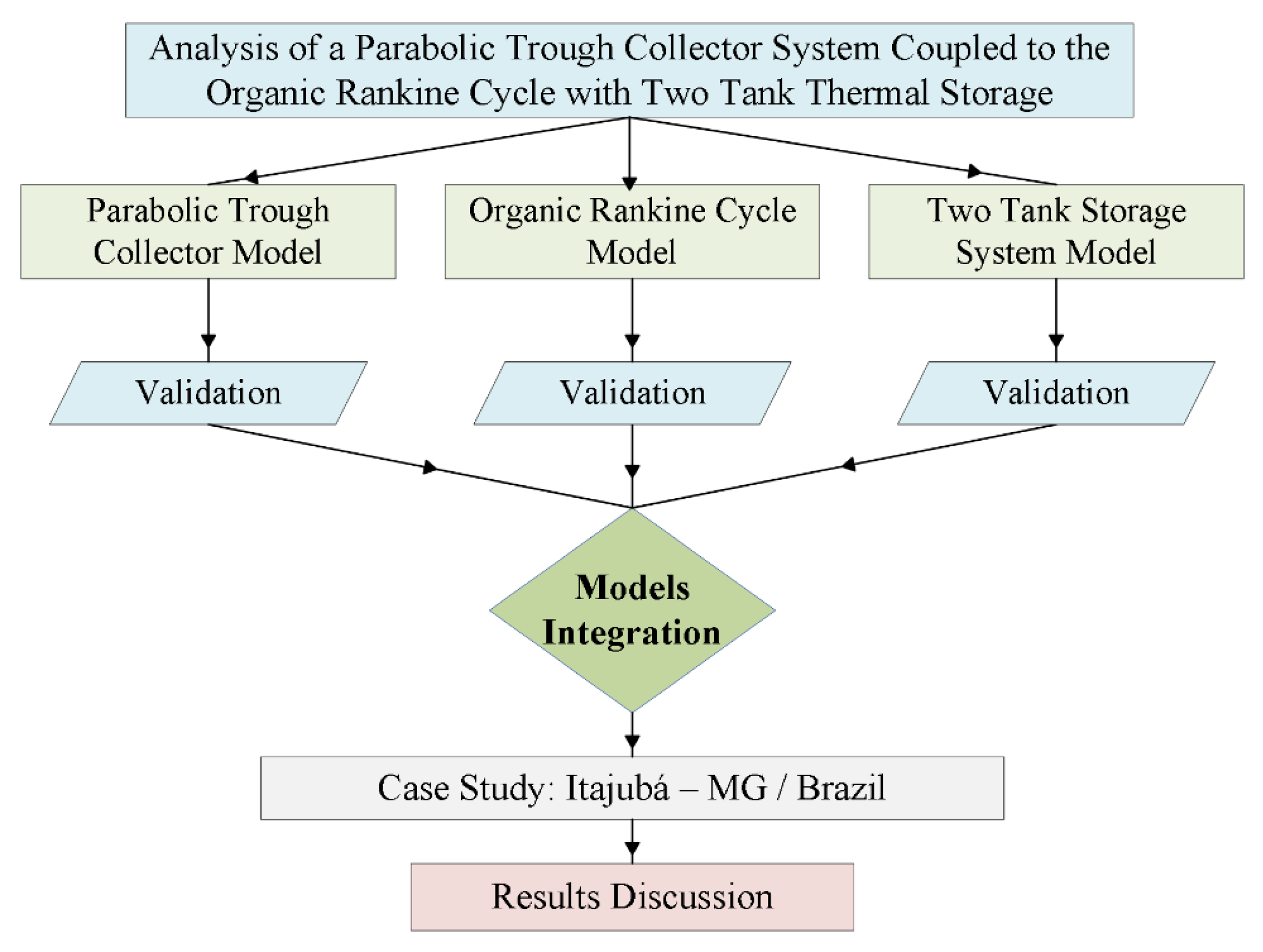
2. Materials and Methods
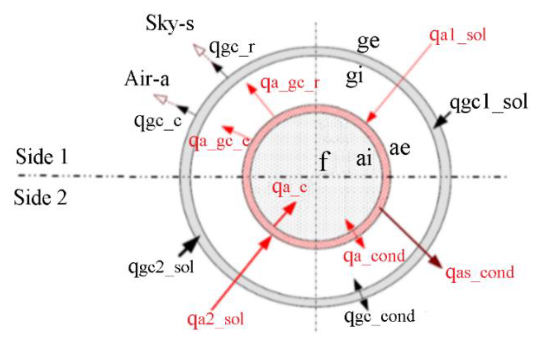
In order to assess the behavior of the system proposed in this paper, Figure 1 depicts the system components [15].
It is important to note that the system configuration proposed herein (Figure 1) is intended for an electricity generation system from a low-or medium- temperature energy source that is environmentally friendly and reasonably efficient, even in locations with a low level of radiation, and that can respond to the intermittence of solar energy.
The operation of this system begins when the solar irradiation reaches the surface of the collectors and is directed and concentrated on the system’s receiver. This component contains in its interior a heat transfer fluid, which is heated. This hot fluid leaves the solar field and enters the hot fluid tank (energy storage system), which is then directed to a heat exchanger (evaporator), where this fluid transfers the energy to the working fluid of the organic Rankine cycle, which is responsible for the generation of electricity. After the heat transfer fluid leaves the evaporator, it is directed to the cold fluid tank (energy storage system) and then re-enters the solar field to repeat the cycle.
The city of Itajubá, Brazil, was selected for the analysis presented in this study, as the Federal University of Itajubá has a Heliothermal Energy Laboratory with a system composed of Parabolic Trough Collectors and an Organic Rankine Cycle to generate electricity using solar energy. Unfortunately, to date, it has not yet been possible to extract sufficient operating data from this system to validate the models presented herein.
Mathematical models developed and integrated by this research were implemented in Matlab. For the Organic Rankine Cycle case, the properties of the different fluids involved in the cycle (water, R-245fa, R-141b, R-123) were retrieved from Coolprop [17].
For Dowtherm A, Dowtherm Q, and syltherm 800, a database with their liquid-state properties was created, retrieving data from manufacturers’ catalogs. These fluids are suitable for heat transfer at atmospheric pressure [18,19,20].
The methodological sequence in Figure 2 reveals the components of the proposed system that were individually modeled. Due to the lack of detailed design and operational data for the system configuration proposed herein, each model was validated individually before it was integrated into one system. Mathematical models developed and integrated by this research were implemented in Matlab.

2.1. Heat Transfer

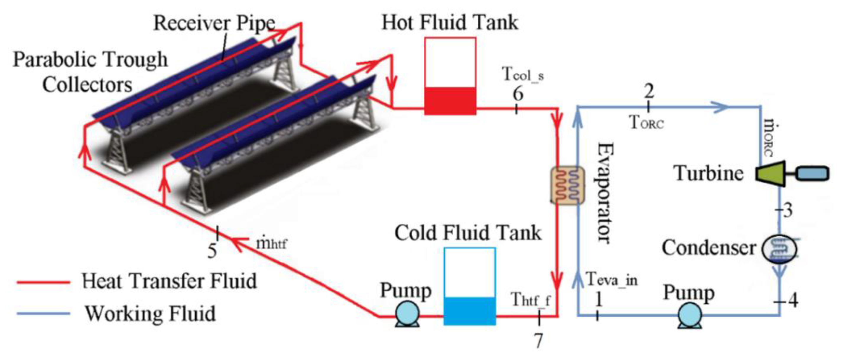
2.1.1. Parabolic Trough Collectors

The heat flow’s non-uniformity along the receiver tube was taken into consideration. For this analysis, the entire receiver tube was divided into two linear halves. Figure 3 shows a cross-section of the receiver tube with the heat transfer rates observed in this study [21].
Side 2 of the receiver tube faced the collector to receive concentrated solar irradiation. In contrast, side 1 faced the opposite side and was affected only by the total solar irradiation (not concentrated). This methodology helped to determine the system of equations that characterizes the behavior of the Parabolic Trough Collectors. The solar irradiation that reached sides 1 and 2 of the receiver was directly absorbed by both the outer surfaces of the absorber tube and the glass cover, as represented by the values (qa1-sol), (qcv1-sol) and (qa2-sol), (qgc2-sol), respectively. Most of the radiant energy absorbed by both sides of the absorber tube was transferred through the steel tube (qa-cond) and then to the heat transfer fluid (qa-c) by convection. The remaining energy was transferred back to the glass cover through thermal radiation (qa_gc-r) and, if there was no vacuum in the annular space between the receiver tube and the glass cover, convection (qa_gc-c). There were also conductive heat losses (qas-cond) through the receiver support brackets. Heat passed through the glass cover by conduction (qgc-cond). This energy was then transferred to the environment by convection (qgc-c) and to the sky by radiation (qgc-r).
Equations (1) and (2) were used to calculate the energy absorbed by the absorber tube and the glass cover on side 1, respectively, at any given time, in addition to all of the other aforementioned considerations [22,23]:
q a 1 - s o l = ( D a e I b + π D a e I d 2 ) τ g c α a
q g c 1 - s o l = ( D g e I b + π D g e I d 2 ) α g c
The energy absorbed by the absorber tube and the glass cover on side 2 were calculated with Equations (3) and (4), respectively:
q a 2 - s o l = ( γ f i ρ C o l K θ I b ) [ a D a e ] τ g c α a
q g c 2 - s o l = ( γ f i ρ C o l K θ I b ) [ a D g e ] α g c

2.1.2. Heat Transfer from the Absorber Tube to the Fluid

Assuming a stationary process and incompressible flow [24], the thermal energy transferred to the heat transfer fluid (HTF) flowing inside the absorber tube can be ascertained by Newton’s law of cooling applied to each side of the receiver, as provided by Equation (5) [25]:
q a _ x - c _ x = π D a i 2 h h t f _ x ( T a i _ x T f )
Heat Transfer Through the Absorber Tube: the heat transfer rate per unit length through the absorber tube’s wall for sides 1 and 2 was determined by Fourier’s Law of Heat Conduction [26], according to Equation (6):
q a _ x - c o n d = π D a e 2 ( 2 k a D a e ln ( D a e D a i ) ) ( T a e _ x T a i _ x )

2.1.3. Heat Transfer from the Absorber Tube to the Glass Cover

Heat losses from the absorber tube were defined as the sum of the heat losses by convection and radiation in the glass cover and the heat losses through the metal supports of the receiver tube. Convective heat losses depend on the pressure inside the annular space (the space between the absorber tube and the glass cover). Therefore, Equation (7) can be used to determine the convective heat loss for sides 1 and 2 of the tube [27]:
q a _ g c _ x - c = ( π D a e 2 ) h a _ c v _ x ( T a e _ x T g i _ x )
Heat loss by radiation per unit length of the outer surface of the absorber tube and the inner surface of the glass cover was estimated for sides 1 and 2 with Equation (8) [17]:
q a _ g c - r _ x = π ( D a e 2 ) σ ε a _ g c 1 [ T a e _ x 4 T g i _ x 4 ]
Conductive Heat Loss Through the Glass Cover: The same method for the absorber tube was applied in order to calculate the heat conduction per unit length through the glass cover for sides 1 and 2 using Fourier’s Law, as given by Equation (9) [28]
q g c _ x - c o n d = π D g e 2 ( 2 k a _ g c D g e ln ( D v e D v i ) ) ( T g e _ x T g i _ x )

2.1.4. Heat Loss from the External Surface of the Glass Cover

As shown in Figure 3, the glass cover’s external surface loses heat by convection and radiation. Heat transfer by radiation occurs between the external surface of the glass cover facing the sky (side 1) and the external surface facing the collector (side 2). Convective heat loss on the external surface of the glass cover was determined by Equation (10) [20]:
q g c _ x - c = ( π D g e 2 ) ( N u g e _ x k a i r _ x D g e ) ( T g e _ x T a m b )
Heat transfer caused by the temperature difference between the external surface of the glass cover and the sky can be calculated for sides 1 and 2 of the tube with Equation (11) [20]:
q g c _ x _ r = ( π D g e 2 ) σ ε g e [ ( T g e _ x 4 ) ( T s 4 ) ]

2.1.5. Heat Transfer through Absorber Tube Support Brackets

According to Forristall [29], the temperature at the base of the supports can be estimated as the ambient temperature outside the absorber tube minus 10 °C. Thus, heat loss in the supports was calculated by Equation (12):
q a b _ c o n d = ( h a b P a b k a b A b _ a b ) 0.5 ( T b T a m b ) / ( 2 L r )
Equation (13) was used to obtain the outlet temperatures of both the control volume and the collector for both sides 1 and 2 of the receiver tube:
T C o l - s = T f + [ q a _ x - s o l + q g c _ x - s o l q g c _ x - c q g c _ x - r 0.5 m ˙ h t f C p _ h t f ] ( D i f f e r e n t i a l   E l e m e n t )
Finally, the temperature of the fluid at the outlet of the receiver was calculated as the average temperature of each side of the tube [30]. Based on the predefined relationships and the outlet temperature of the collector, it is possible to determine the collector’s efficiency through Equation (14):
η C o l e t o r = m ˙ h t f C p _ h t f ( T C o l - s T f ) I b D c o l L C o l

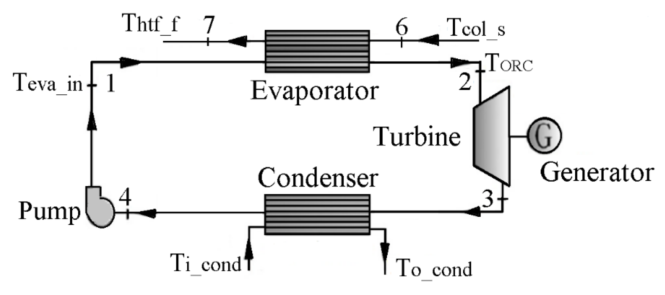
2.2. Organic Rankine Cycle

Figure 4 presents the ORC configuration modeled in this study. As shown, the behavior of a simple ORC was modeled without any additional variations in the system’s configuration.
The mass flow rate of the working fluid ( m ˙ orc) in the ORC unit was determined by Equation (15) [29]:
m ˙ o r c = m ˙ h t f C p _ h t f ( T c o l _ s T h t f ) h 2 h 1
Therefore, the heat supplied by the heat transfer fluid in the evaporator was given by Equation (16) [30]:
Q f _ h t f = m ˙ h t f C p _ h t f ( T C o l _ S T h t f _ f )

2.2.1. Turbine

Its efficiency was calculated by Equation (17) [30]:
η t = W ˙ r e a l - t W ˙ i s e - t = m ˙ o r c ( h 2 h 3 ) m ˙ o r c ( h 2 h 3 i s e )
Accordingly, the turbine’s power was provided by Equation (18):
W ˙ r e a l - t = m ˙ o r c ( h 2 h 3 )

2.2.2. Condenser

Equation (19) was used to determine heat rejection [30]:
Q a - c o n = m ˙ a c C p _ a ( T o - a c T i - a c )
The heat extracted from the condenser’s working fluid was given by Equation (20) [30]:
Q e x t - c o n = m ˙ o r c ( h 3 h 4 )

2.2.3. Pump

Its isentropic efficiency was obtained with Equation (21) [30]:
η b = W ˙ i s e - b W ˙ r e a l - b = m ˙ o r c ( h 1 i s e h 4 ) m ˙ o r c ( h 1 h 4 )
Once the different states in the ORC were known, the net outlet work was calculated using Equation (22):
W ˙ n e t = W ˙ r e a l - t W ˙ r e a l - b

2.3. Two-Tank Thermal Storage System

The main parameters and simplifications used to define the model for the thermal storage system are provided in Figure 5.
The variation in the internal energy of the fluid was expressed as a function of time and other design parameters, as shown in Equation (23) [30]:
( u ( t ) m ( t ) ) t = m ˙ i n h ( T i n ) m ˙ o u t h ( T ( t ) ) + q s o l a r q l o s s _ t
The variation of the mass of the fluid inside the tank as a function of time was determined by Equation (24) [31]:
m ( t ) = m 0 + t   ( m ˙ i n m ˙ o u t )
Equation (25) was applied to find the contribution of solar irradiation [30]:
q s o l a r = [ q s o l a r _ r o o f + q s o l a r _ w a l l ]
Equation (26) was used to determine the contribution of solar irradiation to the tank walls [30]:
q s o l a r _ r o o f = [ I b   cos ( θ z ) + I d ] α s u r A r o o f
The contribution of solar irradiation to the roof of the tank was provided by Equation (27) [30]:
q s o l a r _ r o o f = [ I b   sin ( θ z ) A w a l l p + I d 2 ( 1 + cos ( π 2 ) ) A w a l l + I g 2 ρ l a n d ( 1 c o s ( π / 2 ) ) A w a l l ] α s u r
Heat losses in the storage tank were given by Equation (28) [30]:
q l o s s t = [ q r r o o f + q r p n + q r p f ] + [ q c r o o f + q c p n + q c p f ] + [ q c o n d _ b o t t o m ]
To determine radiation losses, Equations (29)–(31) were applied [31]:
q r _ r o o f = A e x t _ r o o f σ   ε s u p ( T r o o f _ o 4 T s 4 )
q r _ p n = A e x t _ n σ   ε s u p ( T w a l l _ u 4 T a m b 4 )
q r _ p f = A e x t _ f σ   ε s u p ( T w a l l _ s 4 T a m b 4 )
To determine convective heat losses, Equations (32)–(34) were used [31]:
q c _ r o o f = A e x t _ r o o f h a i r _ r o o f ( T r o o f _ o T a m b )
q c _ p n = A e x t _ n h a i r _ n ( T r o o f _ u T a m b )
q c _ p f = A e x t _ f h a i r _ f ( T r o o f _ s T a m b )
Conductive heat losses from the tank floor to the external surface of the tank’s insulation material were calculated with Equation (35) [31,32]:
q c o n d _ b o t t o m = ( T f T b o t t o m _ i s o l e s t e e l _ b o t t o m k s t e e l A i n t _ b o t t o m + e i s o l _ s k i s o l A e x t _ i )
The aforementioned equations and considerations provided the basis to solve Equation (36), a first-order ordinary differential equation that can be used to calculate the temperature of the fluid storage medium at any given time:
T _ f = f ( t ,   m 0 ,   m ˙ i n ,   T c o l _ s , m ˙ s a ,   C f ,   e s t e e l ,   e i s o ,   k s t e e l ,   k i s o ,   A t a n k ,   Q l o s s ,   q s o l a r )

2.4. Validation of Mathematical Models

Due to the lack of detailed information on the system proposed in this study, this section presents the individual validation of each model. Table 1 provides the characteristics of the collectors installed at the Dead Sea Medical Resort, which were used to validate the parabolic trough collectors model.
The research conducted by Khaled [33] was used to validate the model for the Cylindrical Parabolic Collectors. The author of this particular paper provides the experimental data for a system installed on the roof of a building in Jordan called the Dead Sea Medical Resort, which is located at a latitude of 31.714° N and a longitude of 35.586° E. Table 2 shows the deviation between the outlet temperatures of the water in the experimental tests conducted by Khaled [33] and the temperatures obtained with the model presented in this paper (NEST model).
The maximum difference between the reference data and the data from the NEST model was 4.7%, while the minimum difference was 1.1% for the collector outlet temperature (Table 2). These differences are mainly due to the lack of some data in the results presented by Khaled [33], which were adopted in this simulation. These parameters include the intercept factor, the inside and outside diameters of the glass cover, emissivity, and the thermal conductivity of the glass cover.
The design and experimental data for a 1 kW ORC, provided by Muhammad et al. [34] were used to validate the mathematical model of the Organic Rankine Cycle. Table 3 compares the results of the study by Muhammad et al. [34] and the model developed in this paper.
Given the parameters in Table 3, it is possible to conclude that the results obtained herein are in close agreement with the reference data. Based on the comparison, the maximum difference was 7.8% for the heat rejection in the condenser, and the minimum difference was 1.0 for the turbine pressure (1.0). These differences are mainly due to the lack of some data in the findings provided by the reference [34], such as the area of the evaporator and the efficiency of electricity generation. Finally, the findings presented by Zaversky et al. [35] were utilized to validate the thermal storage system model.
The authors characterized a system that uses molten salt as a storage medium as well as two tanks with a diameter of 38.5 m and a height of 14 m. Because of the advanced computational resources required to simulate the thermal storage system, this analysis was limited to a period of 4 h and 45 min, whereas Zaversky et al. [35] exhibited the results for a total period of 6 days. Table 4 shows the fluid temperatures provided by Zaversky et al. [35] and those obtained from the NEST model, both of which register an initial temperature of 386 °C for the fluid. A period of 4 h and 45 min was applied in this analysis.
Based on the data presented in Table 4, it was possible to determine a maximum temperature drop of 1.7 °C from the reference temperature. The mathematical model resulted in a maximum temperature drop of 2.0 °C, revealing a 15.8% difference between these values. A comparison of the temperatures obtained during the experimental period resulted in a maximum difference of 0.08%, thus ensuring the validity of the proposed model. These differences may be explained by the lack of some data, such as ambient temperature, wind speed, and fluid level in the tank.

3. Results

Table 5 demonstrates the design parameters for the solar field used to assess the collectors with the selected heat transfer fluids.
The parameters listed in Table 5 were used to conduct various analyses of the solar field. Figure 6 shows the behavior of the solar field’s efficiency and thermal losses with four heat transfer fluids: Water, Dowtherm A, Dowtherm Q, and Syltherm 800.
A constant volumetric flow of 17 m3/h was defined in order to evaluate the system under the same operating conditions. As observed in Figure 6, efficiency decreases as the operating temperature increases, which is a consequence of the increasing heat losses. Based on the experimental conditions, for a temperature range between 60 °C and 90 °C, the highest solar field efficiencies were obtained for Syltherm 800, while water resulted in the lowest efficiency. For temperatures above 93 °C, there was no significant difference in solar field efficiency for the heat transfer fluids used in the analysis. Syltherm 800, Dowtherm A, and Dowtherm Q provided the highest temperatures in the solar field.
The absorber tube was coated with the Solel UVAC Cermet selective coating, for total solar irradiation of 768 W/m2. There was a small difference between the temperatures on sides 1 and 2 of the absorber tube, with a maximum difference of 0.2 °C. There are two possible explanations for this behavior: (i) the final temperature was given as an average of the temperature of sides 1 and 2, and (ii) the chaotic behavior of the fluid caused a mixture of currents to flow along the tube.

3.1. Results of the Organic Rankine Cycle Coupled with the Parabolic Trough

The analysis of the Organic Rankine Cycle was based on the configuration of the Parabolic Trough Collectors presented in Table 5, as both the PTC and ORC form an integrated operation. Moreover, the geometric and operating parameters of the evaporator were also taken into account, as shown in Table 6. Based on the results in the previous section, water was used as the heat transfer fluid and the Solel UVAC Cermet selective coating was applied in the solar field. Water use represents a prospective solution, given its low environmental impact, low cost, and high availability. The working fluids were chosen according to their low ozone depletion potential (ODP): 0 for R-245fa, 0.12 for R-141b, and 0.022 for R-123. As for their global warming potential (GWP), these working fluids present acceptable values compared to other fluids: 950 for R-245fa, 713 for R-141b, and 76 for R-123 [15].
In Figure 7, it is possible to observe that, initially, the generation of electricity increases as the operating temperature increases, until a maximum value is reached. After this maximum is reached, the system’s electrical energy decreases as the working fluid temperature increases. This occurs because the temperature difference between the water and the working fluid decreases during the process. The electric power decreases until the fluid reaches the minimum difference in temperature, as defined by the pinch point of the evaporator. Considering the fluids in this analysis, R-245fa (11.7 kW) generated the most power, followed by R-141b (10.4 kW) and R-123 (8.8 kW). This behavior shows that for the system operating with R-245fa, there is a greater utilization or extraction in the turbine of the energy transported by the working fluid R-245fa than the maximum utilization that occurs in the ORC system, working with R-141b and R-123. From the exergetic point of view, the ORC system configuration presents higher exergetic efficiency than the other system configurations evaluated in this research. These exergetic effects and behaviors are evidenced in the work of [15].
Figure 8 demonstrates that the unit reaches its maximum performance when the fluid is close to its maximum operating temperature. This indicates that the boiling point causes an increase in the thermal efficiency of this type of system. As for the decrease in the level of performance caused by the rise in temperature at the inlet of the turbine, the maximum efficiency value of the ORC unit is the result of an optimal boiling point value. The ORC attained its highest efficiency with R-141b, followed by R-123 and R-245fa. The maximum efficiency values were 9.86% for R-141b at a temperature of 146 °C and a mass flow rate of 0.24 kg/s, 9.4% for R-123 at a temperature of 125 °C and a mass flow rate of 0.3 kg/s, and 8.9% for R-245fa at a temperature of 106 °C and a mass flow rate of 0.44 kg/s.
Figure 9 presents the overall efficiency of the integrated PTC and ORC system. The efficiency of the system increases as the temperature of the working fluid increases until the point of maximum efficiency for the different heat transfer fluids is reached, which falls within a temperature range between 105 °C and 113 °C. As of this point, the system’s performance level declines as the temperature of the working fluid at the outlet of the collector rises. For the proposed configuration, the use of Syltherm 800 (6.12% at a temperature of 109 °C) as a heat transfer fluid resulted in the system’s maximum overall efficiency, followed by Dowtherm Q (6.11% at a temperature of 110 °C) and Dowtherm A (6.10% at a temperature of 111 °C). When water was applied to the system, the maximum efficiency was 6.11% at a temperature of 113 °C. For this analysis, the R-245fa was used as the working fluid for the ORC system.

3.2. Thermal Storage System Coupled to the Integrated PTC-ORC System

The parameters for the Parabolic Trough Collectors presented in Table 7 and the solar irradiation profile for the city of Itajubá, Minas Gerais, Brazil, on March 1, 2019, was used to design the tanks of the thermal storage system. The ORC’s pump efficiency was determined to be at 75%. The turbine’s mechanical efficiency was 92%, while the efficiency of the electric generator was at 92%.
Solar irradiation data for the city of Itajubá (1 March 2019) were obtained from the weather station installed at the Federal University of Itajubá (UNIFEI). For the selected date, the evaluation period began at 8:20 am and ended at 4:30 pm. During this period, the lowest overall solar irradiation values were 459 W/m2 (8:20 am) and 424 W/m2 (4:30 pm), and the maximum solar irradiation value was 980 W/m2 at 12:40 pm.
Table 8 shows the working parameters of the system configuration defined to generate 7.4 kW.
Figure 10 shows the temperature variation of the fluid inside the thermal storage tanks during the charging and discharge period.
The following issues of the energy storage system were studied:
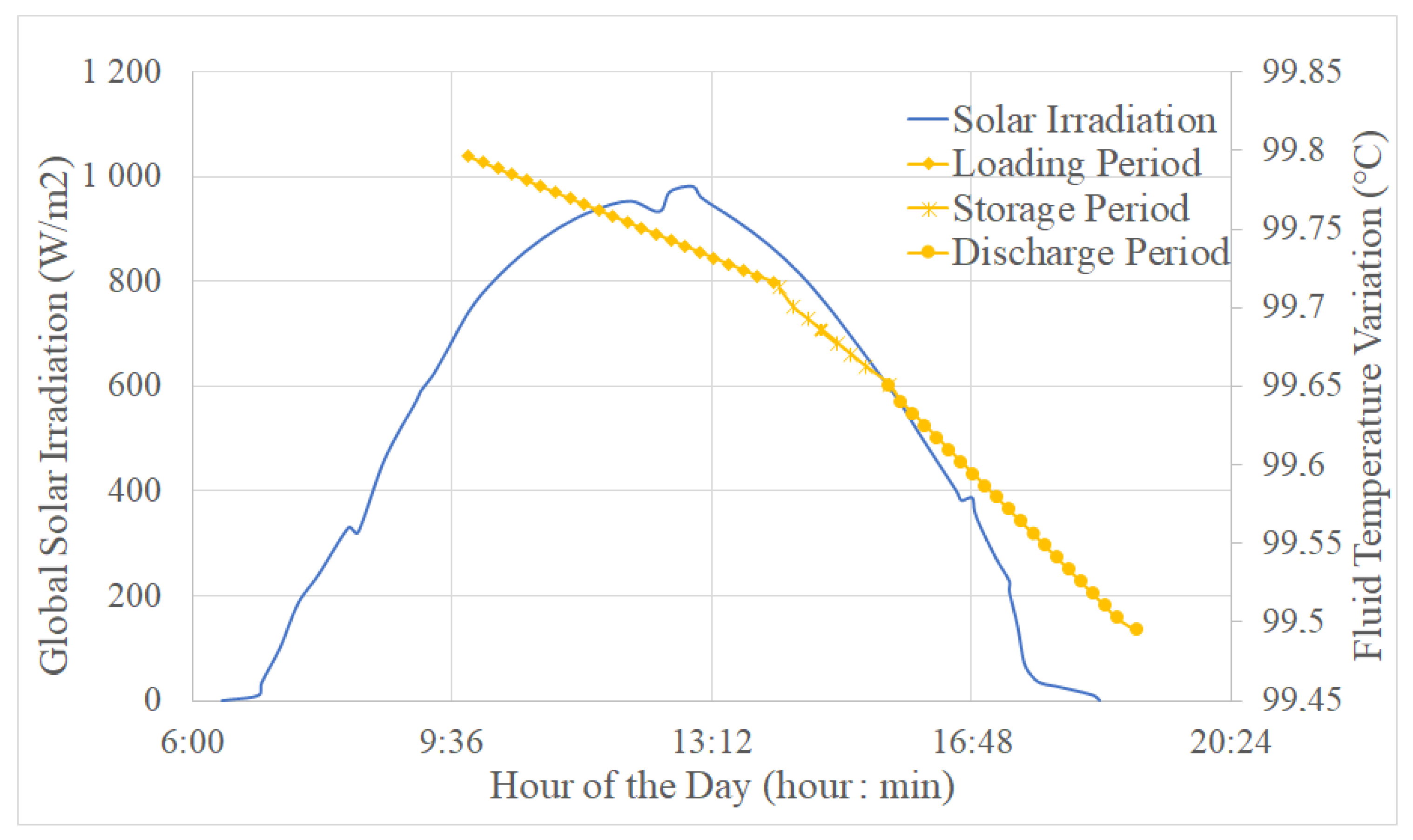
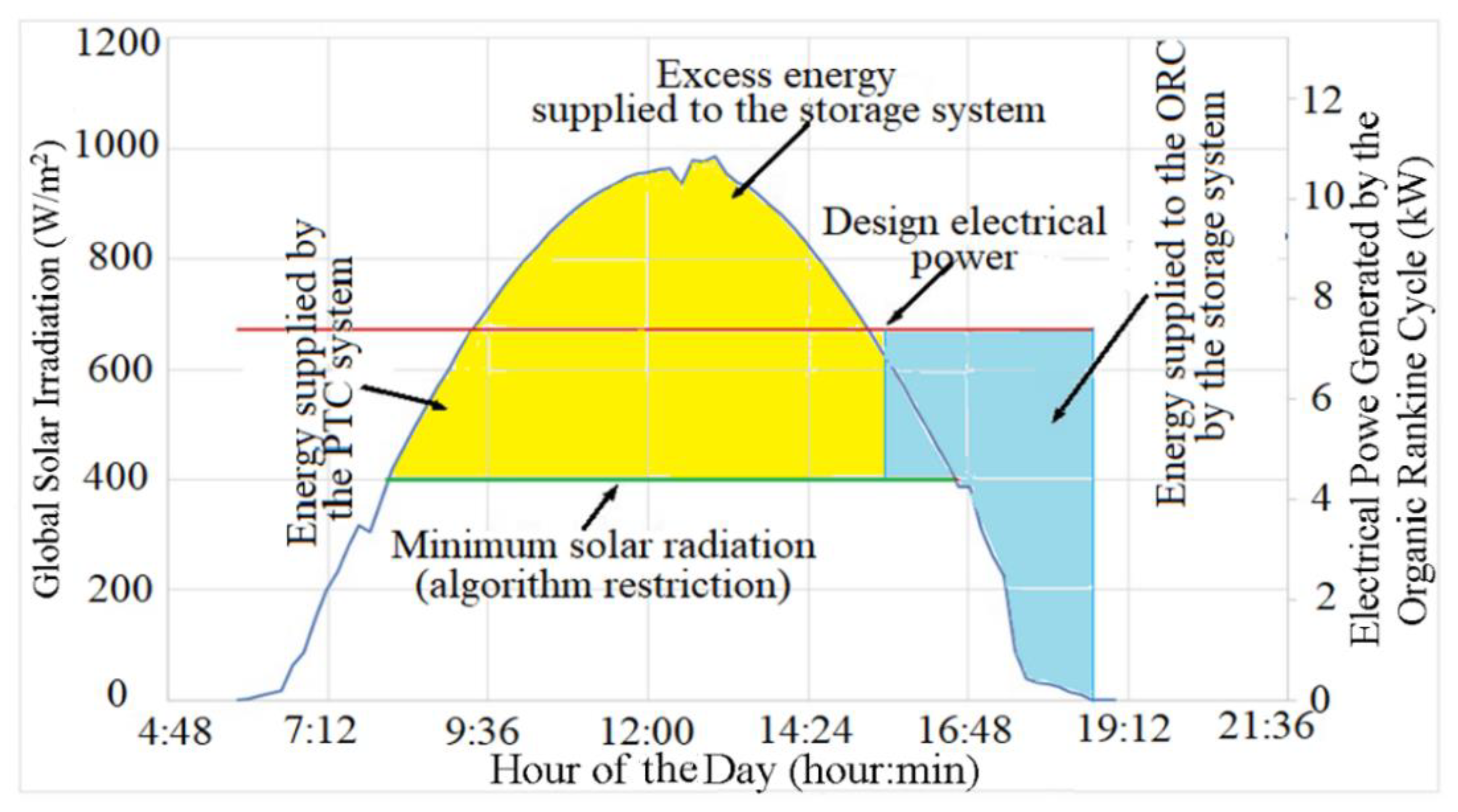
  • Charging periods: In the system operation at this stage, the fluid or storage medium found in the cold tank was made to flow through the solar field when the maximum solar irradiation conditions were reached (higher solar irradiation at 694 W/m2). Once the fluid was heated, it was charged with the fluid coming out of the solar field’s hot tank.
  • Discharge period: This took place when the solar irradiation dropped below 694 W/m2, a condition in which the fluid contained in the hot tank was discharged in order to supply the energy necessary to power the ORC system.
The analysis at this stage can be summarized as follows (Figure 9):
  • For the tank’s charging period, which lasted 3 h and 40 min, the maximum temperature drop was 0.084 °C.
  • The time required for thermal storage was 4800 s (1 h and 10 min). After this time, the stored energy needed to be used, and the fluid’s discharge process began to maintain the power produced by the ORC at approximately 7.4 kW. During this period, the maximum temperature drop was 0.06 °C.
  • At the end of the discharge period, the final temperature of the fluid was 99.49 °C. During the discharge period, which lasted 3 h and 26 min, the maximum temperature drop was 0.15 °C.
  • For the complete operation of the thermal storage system, there was a difference of 0.31 °C between the design temperature (99.8 °C) and the temperature at the end of the discharge period.
  • At this point, it is possible to establish that when comparing the energy storage system’s behavior with and without considering heat losses (for the conditions evaluated in Table 8 and Table 9), the fluid temperature remains constant (99.8 °C) from the time it enters the hot tank onward, regardless the environmental conditions and the fluid temperature inside the hot tank.
  • An evaluation of the thermal storage system demonstrated that a tank with a diameter of 4 m and a height of 4.55 m using Dowtherm A, a fluid storage medium, and heat transfer fluid from the solar field guarantees electricity generation for 3 h and 26 min, based on the design parameters proposed in this paper and on a working fluid inventory of 57.15 m3.
From the analyses and calculations performed for the thermal storage system, it was possible to determine design and operational parameters, which provided fundamental bases to understand the thermal behavior of this type of technology. We were also able to determine variables in order to perform other calculations, such as exergy, as well as useful calculations to determine available energy for a certain process.
From the analysis of the thermal storage system, it was possible to establish that, when the hot tank charging process was performed, the inlet mass flow to the tank was maintained within a range of 4.72 to 4.12 kg/s. The operation of the two-tank thermal storage system showed that during the loading process, peak thermal powers of 740 kW can be reached. For the unloading process of the storage system, the obtained values of thermal power in the system reach values of 738 kW. From this analysis, it was also determined that there was an exergy efficiency during the charge period of 98.91%, a value representing available energy inside the thermal storage tank during this first period. For the storage period, the exergy efficiency was 99.98%, and it remained constant until the end of the storage period. Finally, for the discharge period, the exergy efficiency was 99.65%, representing the amount of energy that could be recovered from the storage tank during the previously defined periods and which can be delivered to the power block (ORC system) to guarantee its continuous electricity generation.
Figure 11 shows the curve for the integrated operation of the solar thermal collector, the thermodynamic power cycle, and the thermal storage system for the selected date, March 1, 2019. This figure depicts the periods in the day when the PTC and ORC were in operation. It also demonstrates the period when thermal energy was supplied to the storage system and the period when thermal energy from the storage system was used to power the ORC to generate electric power (~7.4 kWe). For this period of operation, it was possible to determine the contribution of the PTC and the thermal storage system to electricity production. The Parabolic Trough Collectors contributed 63.6% of the energy supplied to the ORC and the storage system between the hours of 9:30 am and 3:30 pm. In comparison, the storage system provided 36.4% of the energy supplied to the ORC from 3:30 pm to 6:51 pm, when the parabolic trough collectors were not in operation.
When comparing this research with others found in the literature, it is noticeable that many studies sought to explore different energy storage routes, such as packed-bed thermochemical storage and power blocks, such as Brayton and Conventional Rankine Cycles. Results from this work and state-of-the-art research show that the precision of this type of system’s configuration characterization depends on the type of design and the operational parameters considered.
Now, some of the state-of-the-art works used to compare our work will be briefly described. Guarino et al. [37] presented the analysis of a seasonal thermal energy storage system (Borehole Thermal Energy Storage (BTES)) coupled to a Dish Stirling System. In this work, the authors demonstrated the possibility of covering 44% of the electricity produced by the system through a novel energy storage system. In the case of the present investigation, it was possible to determine that the thermal storage system supplies 36.4% of the energy supplied to the ORC system. Sadeghi et al. [38] presented a Central Tower System with thermal storage using a phase change material (PCM) integrated into a multigeneration energy plant with a Brayton cycle. In such a configuration, the solar field and the energy storage system contribute to keeping the electricity generation in the gas turbine within the range of 25 to 58 MWe, with operating temperatures in the range of 572 to 627 °C. In our work, the power generation was found to be 7.4 kWe, with turbine inlet temperatures of 99.49 °C. Battisti et al. [39] analyzed packed-bed thermal energy storage systems for concentrating solar-powered plants. Supercritical CO2 was used to operate the solar field, the Brayton cycle, and the storage system, allowing it to reach temperatures at the inlet of the power block in the range of 400 to 650 °C. For this thermal storage system, the highest efficiency values (90%) were achieved for a thermal insulation thickness of 0.5 m throughout the entire system. Regarding the research developed in our work, the maximum thermal insulation thickness was set at 0.4 m for the hot tank.

4. Conclusions

The thermal efficiency values for the solar field (70–72%), the ORC (9.9%), and the overall system (6.1%) presented in the results match the values reported in the literature, thus validating the methodology proposed in this paper.
In the analysis of sides 1 and 2 of the receiver, a minimal temperature difference was found between them, but there was a significant difference in the solar irradiation values for each side. Furthermore, the results of the study indicate that the average temperature of sides 1 and 2 of the receiver tube may be considered in the operation of the PTC system. This way, it was possible to avoid consuming long periods of time with computational tasks involving simulations of the system in the non-uniform distribution of solar irradiation in the receiver.
The methodology used to design the storage system made it possible to determine the dimensions and characteristics of the system which allow the design to generate electric power (7.4 kW) even during a period with a lack of solar irradiation. According to the results presented, it is possible to conclude that the system responds properly to a lack of solar irradiation, which corresponds to 36.4% of the operational period of the ORC.
Results from the thermal storage system show an exergy efficiency between 98 and 99% in its different stages (charging, storage, discharge), revealing the important contribution of this type of system to the performance of Solar Collector technologies. Moreover, such systems help to guarantee power generation and continuous supply under the requirements and standards established for a given process, with a high usage efficiency (i.e., exergy efficiency c.a., 99%). Furthermore, the approach presented in this work helps to determine the impact of heat losses on this type of thermal storage technology generation system’s performance.
Parabolic Cylindrical Collector technologies have a promising future in the field of Concentrating Solar Technologies. Thus, based on the methods developed in this research, it is possible to consolidate and strengthen the knowledge related to the operation of this type of technology integrated into energy storage systems. The review of the literature retrieved works regarding storage systems, such as concrete, hydraulic, thermochemical tank, and two-tank systems. Undoubtedly, the two-tank system is favored in commercial plants due to its widespread implementation. Therefore, this research implemented a detailed methodology in order to characterize this type of system. On the other hand, other research does not allow relationships referring to considerations and project parameters used to be found, which would clearly define the operation of the system proposed in this work.

Author Contributions

G.C.C.: writing—original manuscript and revisions, simulations. Y.C.E.: methodology, simulations, supervision. L.S.M.C.: visualization, editing. A.L.G.N.: investigation, software—Matlab support. O.J.V.: reviewing and editing. E.E.S.L.: conceptualization, methodology, investigation. E.I.G.V.: simulations, supervision. A.A.M.: conceptualization, editing. All authors have read and agreed to the published version of the manuscript.

Funding

The University Señor de Sipán provided the funds to cover the APC of the paper.

Acknowledgments

Authors would like to thank the Coordination for the Improvement of Higher Education Personnel (CAPES), the National Council of Scientific and Technological Development (CNPq), and the Minas Gerais State Agency for Research and Development (FAPEMIG) for their cooperation and financial support throughout this investigation, as well as CPFL Energia and the Brazilian Electricity Regulatory Agency (ANEEL).

Conflicts of Interest

The authors declare no conflict of interest.

Nomenclature

AArea (m2), absorber, collector aperture width (m), heating
bNormal, base, nozzle blade
cConvection
dDiffuse
D Diameter (m)
evaEvaporator
f Fluid
h Convective heat transfer coefficient, enthalpy (W/m2 K), hub
I Solar irradiation (W/m2)
kThermal conductivity
K θ Incidence-angle modifier
LLength (m)
m ˙ Mass flow rate (kg/s)
nNitrogen
qHeat transfer rate per unit length (W/m)
QHeat absorbed (W)
rReceiver, radiation, radius (m)
sSky, outlet, shroud, storage, dry section
uWet section
xSide 1 or side 2
Greek Symbols
α Absorbance
ε Emissivity coating, rotor radius ratio
σStefan–Boltzmann constant
ρReflectance, density (kg/m3)
τ Transmittance
θ Angle of incidence
γfiIntercept factor
Subscripts
0Total
1Receiver side one
2Receiver side two
a m b Ambient
abAbsorber support bracket
aeExternal absorber
aiInternal absorber
ColCollector
condConduction
conCondenser
h t f Heat transfer fluid
inInlet
i s e Isentropic
geExternal glass cover
giInternal glass cover
gcGlass cover
o u t Outlet
orcOrganic Rankine Cycle
PTCParabolic Trough Collector
wfworking fluid
satThermal storage system
s u r Surroundings

References

  1. Peter, J. How does climate change affect electricity system planning and optimal allocation of variable renewable energy? Appl. Energy 2019, 252, 113397. [Google Scholar] [CrossRef]
  2. Lin, B.; Jia, Z. Is emission trading scheme an opportunity for renewable energy in China? A perspective of ETS revenue redistributions. Appl. Energy 2020, 263, 114605. [Google Scholar] [CrossRef]
  3. Cuesta, M.A.; Castillo-Calzadilla, T.; Borges, C.E. A critical analysis on hybrid renewable energy modeling tools: An emerging opportunity to include social indicators to optimize systems in small communities. Renew. Sustain. Energy Rev. 2020, 122, 109691. [Google Scholar] [CrossRef]
  4. Vetter, C.; Wiemer, H.J.; Kuhn, D. Comparison of sub- and supercritical Organic Rankine Cycles for power generation from low-temperature/low-enthalpy geothermal wells, considering speci fi c net power output and efficiency. Appl. Therm. Eng. 2013, 51, 871–879. [Google Scholar] [CrossRef]
  5. Wasserbauer, C.A.; Glassman, A.J. FORTRAN Program for Predicting the Off-Design Performance of Radial Inflow Turbines; NASA Technical Note TN D-8063; NASA: Washington, DC, USA, 1 September 1975.
  6. Borunda, M.; Jaramillo, O.; Dorantes, R.; Reyes, A. Organic Rankine Cycle coupling with a Parabolic Trough Solar Power Plant for cogeneration and industrial processes. Renew. Energy 2016, 86, 651–663. [Google Scholar] [CrossRef]
  7. Quoilin, S. Sustainable Energy Conversion through the Use of Organic Rankine Cycles for Waste Heat Recovery and Solar Applications. Ph.D. Thesis, University of Liege, Liege, Belgium, 2011. Available online: https://hdl.handle.net/2268/96436 (accessed on 1 October 2020).
  8. He, Y.L.; Mei, D.H.; Tao, W.Q.; Yang, W.W.; Liu, H.L. Simulation of the parabolic trough solar energy generation system with Organic Rankine Cycle. Appl. Energy 2012, 97, 630–641. [Google Scholar] [CrossRef]
  9. Derbal-Mokrane, H.; Amrouche, F.; Omari, M.N.; Yahmi, I. Hydrogen production through parabolic trough power plant based on the Organic Rankine Cycle implemented in the Algerian Sahara. Int. J. Hydrogen Energy 2021, 46, 32768–32782. [Google Scholar] [CrossRef]
  10. Marinheiro, M.M.; Coraça, G.M.; Cabezas-Gómez, L.; Ribatski, G. Detailed transient assessment of a small-scale concentrated solar power plant based on the organic Rankine cycle. Appl. Therm. Eng. 2022, 204, 117959. [Google Scholar] [CrossRef]
  11. Chacartegui, R.; Vigna, L.; Becerra, J.A.; Verda, V. Analysis of two heat storage integrations for an Organic Rankine Cycle Parabolic trough solar power plant. Energy Convers. Manag. 2016, 125, 353–367. [Google Scholar] [CrossRef]
  12. Suresh, N.S.; Thirumalai, N.C.; Rao, B.S.; Ramaswamy, M.A. Methodology for sizing the solar field for parabolic trough technology with thermal storage and hybridization. Sol. Energy 2014, 110, 247–259. [Google Scholar] [CrossRef]
  13. Catapano, F.; Frazzica, A.; Freni, A.; Manzan, M.; Micheli, D.; Palomba, V.; Sementa, P.; Vaglieco, B. Development and experimental testing of an integrated prototype based on Stirling, ORC and a latent thermal energy storage system for waste heat recovery in naval application. Appl. Energy 2022, 311, 118673. [Google Scholar] [CrossRef]
  14. Khedher, N.B.; Bantan, R.A.; Kolsi, L.; Omri, M. Performance investigation of a vertically configured LHTES via the combination of nano-enhanced PCM and fins: Experimental and numerical approaches. Int. Commun. Heat Mass Transf. 2022, 137, 106246. [Google Scholar] [CrossRef]
  15. Caballero, G.E.C. Modelagem do Comportamento Integrado de um Sistema de Coletor Cilíndrico Parabólico Operando com Ciclo Rankine Orgânico e Armazenamento Térmico de dois Tanques. Ph.D. Thesis, Universidade Federal De Itajubá, Itajuba, Brazil, 2018. [Google Scholar]
  16. Hachicha, A.A.; Rodriguez, I.; Capdevila, R.; Oliva, A. Heat transfer analysis and numerical simulation of a parabolic trough solar collector. Appl. Energy 2013, 111, 581–592. [Google Scholar] [CrossRef] [Green Version]
  17. Bell, I.H.; Wronski, J.; Quoilin, S.; Lemort, V. Pure andPseudo-pure Fluid Thermophysical Property Evaluation and the Open-Source Thermophysical Property Library CoolProp. Ind. Eng. Chem. Res. 2014, 53, 2498–2508. [Google Scholar] [CrossRef] [Green Version]
  18. Dow. SYLTHERM 800—Heat Transfer Fluid 800. Product Technical Data; Dow: Midland, MI, USA, 1997. [Google Scholar]
  19. Dow. DOWTHERM A—Heat Transfer Fluid. Product Technical Data; Dow: Midland, MI, USA, 1997. [Google Scholar]
  20. Dow. DOWTHERM Q—Heat Transfer Fluid. Product Technical Data; Dow: Midland, MI, USA, 1997. [Google Scholar]
  21. Cheng, Z.D.; He, Y.L.; Qiu, Y. A detailed nonuniform thermal model of a parabolic trough solar receiver with two halves and two inactive ends. Renew. Energy 2015, 74, 139–147. [Google Scholar] [CrossRef]
  22. Reddy, K.S.; Satyanarayana, G.V. Numerical Study of Porous Finned Receiver for Solar Parabolic Trough Concentrator. Eng. Appl. Comput. Fluid Mech. 2008, 2, 172–184. [Google Scholar] [CrossRef] [Green Version]
  23. Ravi, K.; Reddy, K.S. Thermal analysis of solar parabolic trough with porous disc receiver. Appl. Energy 2009, 86, 1804–1812. [Google Scholar] [CrossRef]
  24. Al-Shemmeri, T. Engineering Thermodynamics. Nature 1958, 181, 1028. [Google Scholar]
  25. Lu, J.; Ding, J.; Yang, J.; Yang, X. Nonuniform heat transfer model and performance of parabolic trough solar receiver. Energy 2013, 59, 666–675. [Google Scholar] [CrossRef]
  26. Cengel, Y. Heat and Mass Transfer a Practical Approach, 3rd ed.; McGraw Hill Book Company: New York, NY, USA, 2006. [Google Scholar]
  27. Dudiey, V.E.; Kolb, G.J.; Sloan, M.; Kearney, D. SEGS LS 2 Solar Collector Rest Result. Technical Report. SAND94-1884. 1994. Available online: https://www.osti.gov/biblio/70756 (accessed on 1 May 2020).
  28. Good, P. Heat Transfer Modeling of a Solar Parabolic Trough Receiver by Direct Simultion Monte Carlo Method. Master’s Thesis, Swiss Federal Institute of Technology, Zurich, Switzerland, 2011. [Google Scholar] [CrossRef]
  29. Forristall, R. Heat Transfer Analysis and Modeling of a Parabolic Trough Solar Receiver Implemented in Engineering Equation Solver. NREL/TP-550-34169. 1 October 2003. Available online: https://www.nrel.gov/docs/fy04osti/34169.pdf (accessed on 12 June 2020).
  30. Wagner, M.J.; Gilman, P. Technical Manual for the SAM Physical Trough Model. Technical Report. NREL/TP-5500-51825. Available online: https://www.osti.gov/biblio/1016437/ (accessed on 17 June 2020).
  31. Vaja, I.; Gambarotta, A. Internal Combustion Engine (ICE) bottoming with Organic Rankine Cycles (ORCs). Energy 2010, 35, 1084–1093. [Google Scholar] [CrossRef]
  32. Lukawski, M. Design and Optimization of Standardized Organic Rankine Cycle Power Plant for European Conditions. Master’s Thesis, School for Renewable Energy Science, Akureyri, Iceland, 2009. [Google Scholar]
  33. Khaled, A. Technical and Economic Performance of Parabolic trough in Jordan. Master’s Thesis, Cairo University, Cairo, Egypt, 2012. [Google Scholar]
  34. Muhammad, U.; Imran, M.; Lee, D.H.; Park, B.S. Design and experimental investigation of a 1kW organic Rankine cycle system using R245fa as working fluid for low-grade waste heat recovery from steam. Energy Convers. Manag. 2015, 103, 1089–1100. [Google Scholar] [CrossRef]
  35. Zaversky, F.; García-Barberena, J.; Sánchez, M.; Astrain, D. Transient molten salt two-tank thermal storage modeling for CSP performance simulations. Sol. Energy 2013, 93, 294–311. [Google Scholar] [CrossRef]
  36. Quoilin, S.; Orosz, M.; Hemond, H.; Lemort, V. Performance and design optimization of a low-cost solar organic Rankine cycle for remote power generation. Sol. Energy 2011, 85, 955–966. [Google Scholar] [CrossRef] [Green Version]
  37. Guarino, S.; Buscemi, A.; Ciulla, G.; Bonomolo, M.; Brano, V.L. A dish-Stirling solar concentrator coupled to a seasonal thermal energy storage system in the southern mediterranean basin: A cogenerative layout hypothesis. Energy Convers. Manag. 2020, 222, 113228. [Google Scholar] [CrossRef]
  38. Sadeghi, S.; Ghandehariun, S.; Rezaie, B. Energy and exergy analyses of a solar-based multi-generation energy plant integrated with heat recovery and thermal energy storage systems Steam Rankine cycle. Appl. Therm. Eng. 2021, 188, 116629. [Google Scholar] [CrossRef]
  39. Battisti, F.G.; Passos, L.A.D.A.; Silva, A.K. Performance mapping of packed-bed thermal energy storage systems for concentrating solar-powered plants using supercritical carbon dioxide. Appl. Therm. Eng. 2021, 183, 116032. [Google Scholar] [CrossRef]
Figure 1. Configuration of the integrated Parabolic Trough Collectors and ORC system, adapted from [16].
Energies 15 08261 g001
Figure 2. The methodological sequence used to analyze the proposed system configuration.
Energies 15 08261 g002
Figure 3. Heat transfer model used to evaluate the thermal losses of the receiver, adapted from [21].
Energies 15 08261 g003
Figure 4. Organic Rankine Cycle configuration.
Energies 15 08261 g004
Figure 5. Simplified schematic representation of the thermal storage tank, adapted from [30].
Energies 15 08261 g005
Figure 6. Efficiency and heat losses in the solar field.
Energies 15 08261 g006
Figure 7. Illustrates the behavior of the electric power generated by the Organic Rankine Cycle for different working fluids.
Energies 15 08261 g007
Figure 8. Thermal efficiency of the ORC as a function of the turbine inlet temperature for different working fluids.
Energies 15 08261 g008
Figure 9. The system’s overall efficiency is a function of the temperature at the outlet of the collector.
Energies 15 08261 g009
Figure 10. Variation in fluid temperature during the charging, storage, and discharge period of the storage tanks.
Energies 15 08261 g010
Figure 11. The system’s behavior as a function of solar irradiation in the city of Itajubá, Minas Gerais, Brazil.
Energies 15 08261 g011
Table 1. Characteristics of the PTC-1800 collector.
ComponentParameterValue
ReflectorEdge Angle (°)69.00
Focal length (m)0.78
Length (m)5.09
Aperture width (m)1.80
Height (m)0.26
Coating (m)5 × 10⁻⁴
Reflectance0.85
Absorber tubeMaterialStainless steel
CoatingBlack Chrome
Outer diameter (m)0.038
Wall thickness (m)1.5 × 10⁻³
Absorbance0.94
Glass coverOuter diameter (m)0.065
Wall thickness (m)2.2 × 10⁻³
Transmittance0.92
datadata
Table 2. Characteristics of the PTC-1800 collector.
Solar Irradiation (W/m2)Volumetric Flow
(m3/h)
Ambient Temp. (°C)Wind Speed (m/s)Collector Inlet Temp. (°C)Collector Outlet Temp, Reference (°C)Collector Outlet Temp., NEST Model (°C)Difference (%)
984.23.740.33.057.267.366.51.1
986.03.738.91.175.983.666.52.0
985.93.739.20.476.584.385.91.9
988.03.738.71.579.086.4588.52.3
990.13.738.81.691.997.8101.43.7
989.93.737.41.197.7102.5107.24.7
Table 3. Validation of the mathematical model of the Organic Rankine Cycle.
Reference Results [29]NEST Model ResultsDifference (%)
Wturbine (kW)1.0Wturbine (kW)1.055
Qevaporator (kW)12.27Qevaporator (kW)12.653.1
QCondenser (kW)11.79QCondenser (kW)10.867.8
Mass flow (kg/s)0.054Mass flow (kg/s)0.0552.7
Turbine inlet pressure (bar)12.50Turbine inlet pressure (bar)13.36.4
Turbine inlet temperature (°C)102.5Turbine inlet temp. (°C)104.321.8
Turbine outlet pressure (bar)2.0Turbine outlet pressure (bar)2.021.0
Condenser outlet temp. (°C)30.0Condenser outlet temp. (°C)313.3
Pump outlet temperature (°C)30.78Pump outlet temperature (°C)323.9
Turbine efficiency (%)60.0Working fluid245fa-
Pump efficiency (%)60.0
Table 4. Comparison of the behavior of the fluid temperature in the storage tank.
Time (hour:min)Fluid Temperature-Reference (°C)Fluid Temperature-NEST (°C)Difference (%)
0:00386.0386.0-
1:00385.6385.50.03
2:00385.2385.10.03
3:00384.8384.70.03
4:00384.5384.30.05
4:45384.3384.00.08
Table 5. Design parameters for the solar field.
ParameterValueParameterValue
Collector aperture (m)2.5 [36]Inside diameter absorber tube (m)0.066 [36]
Collector length (m)26Outside diameter absorber tube (m)0.070 [36]
Number of collectors5Inside diameter glass cover (m)0.080 [36]
Absorber tube materialSteel 304Outside diameter glass cover (m)0.088 [36]
CoatingBlack chromeWind speed (m/s)3
ambient temperature (°C)17Initial solar field inlet temp. (°C)45
Table 6. Design parameters for the ORC.
ParameterValueParameterValue
Evaporator area (m2)0.125Pressure ratio5.71
Number of plates60Generator efficiency (%)0.92
Available area (m2)7.5Mechanical efficiency (%)0.92
Table 7. Configuration of the Parabolic Trough Collectors (solar field).
ParameterValueParameterValue
Collector diameter (m)2.5Heat transfer fluidDowtherm A
Collector length (m)18.5Volumetric flow (m3/h)34
Number of collectors4Selective coatingSolel UVAC Cermet
Inside diameter absorber tube (m)0.078Absorber tube materialSteel 304
Outside diameter absorber tube (m)0.082Working fluidR-245fa
Inside diameter glass cover (m)0.09Evaporator area (m2)0.125
Outside diameter glass cover (m)0.098Number of plates60
Table 8. Parameters to generate 7.4 kW.
ParameterValueParameterValue
Thermal design power (kW)7.4Mass flow rate of heat transfer fluid (kg/s)4.5
Solar irradiation (W/m2)694Power cycle efficiency (%)8.7
Temperature of Dowtherm A at the outlet of the collector (°C)99.8Ambient temperature (°C)22
Table 9. Design parameters for storage tanks.
ParameterValueParameterMaterial
Tank roof thickness (m)0.006Thermal insulation of tank roofCalcium silicate board
Tank bottom thickness (m)0.04Thermal insulation of vertical tank wallMineral wool
Vertical tank wall thickness (m)0.04Thermal insulation of tank bottomGlass Foam
Diameter of thermal insulation hot tank (m)0.4Tank materialSteel 304
Thickness of thermal insulation cold tank (m)0.3
Diameter of tanks (m)4Height of tanks (m)4.55
Publisher’s Note: MDPI stays neutral with regard to jurisdictional claims in published maps and institutional affiliations.

