1. Introduction
Material extrusion (MEX) is an additive manufacturing process characterized by the tool-free production of three-dimensional parts by depositing a molten thermoplastic strand layer by layer [
1,
2]. With regard to the associated geometric freedom in design as well as the possibilities for part consolidation and functional integration, MEX offers unique advantages compared to conventional manufacturing processes [
3,
4]. On the other hand, comparatively low mechanical properties often exclude a broad application for the production of end products with high mechanical requirements, so that printed parts are increasingly reinforced with continuous fibers [
5]. However, an existing disadvantage of continuous fiber-reinforced MEX is the limited range of fiber materials [
6]. This is accompanied by a low adaptability of the mechanical properties. By hybridizing several fiber materials in one part, the mechanical properties of the composite material can be adapted to the respective load case.
1.1. Continuous Fiber-Reinforced MEX
A proven method for improving the mechanical properties of parts manufactured by MEX is the incorporation of reinforcing short and continuous fibers [
5,
7,
8]. Continuous fibers are increasingly used for the additive manufacturing of fiber-reinforced thermoplastic parts compared to short-fiber reinforcements, due to their significantly improved mechanical properties [
9,
10]. Continuous fiber-reinforced MEX combines the unique potentials of additive manufacturing processes with the mechanical properties of composite parts. The process principle is based on conventional MEX. In principle, all thermoplastic materials that are also used in conventional MEX can be used as matrix materials. Synthetic carbon, glass and aramid fibers are usually used as reinforcing fibers [
11,
12,
13]. In addition, new research approaches are being pursued to also use natural reinforcing fibers such as flax or jute fibers [
14,
15,
16,
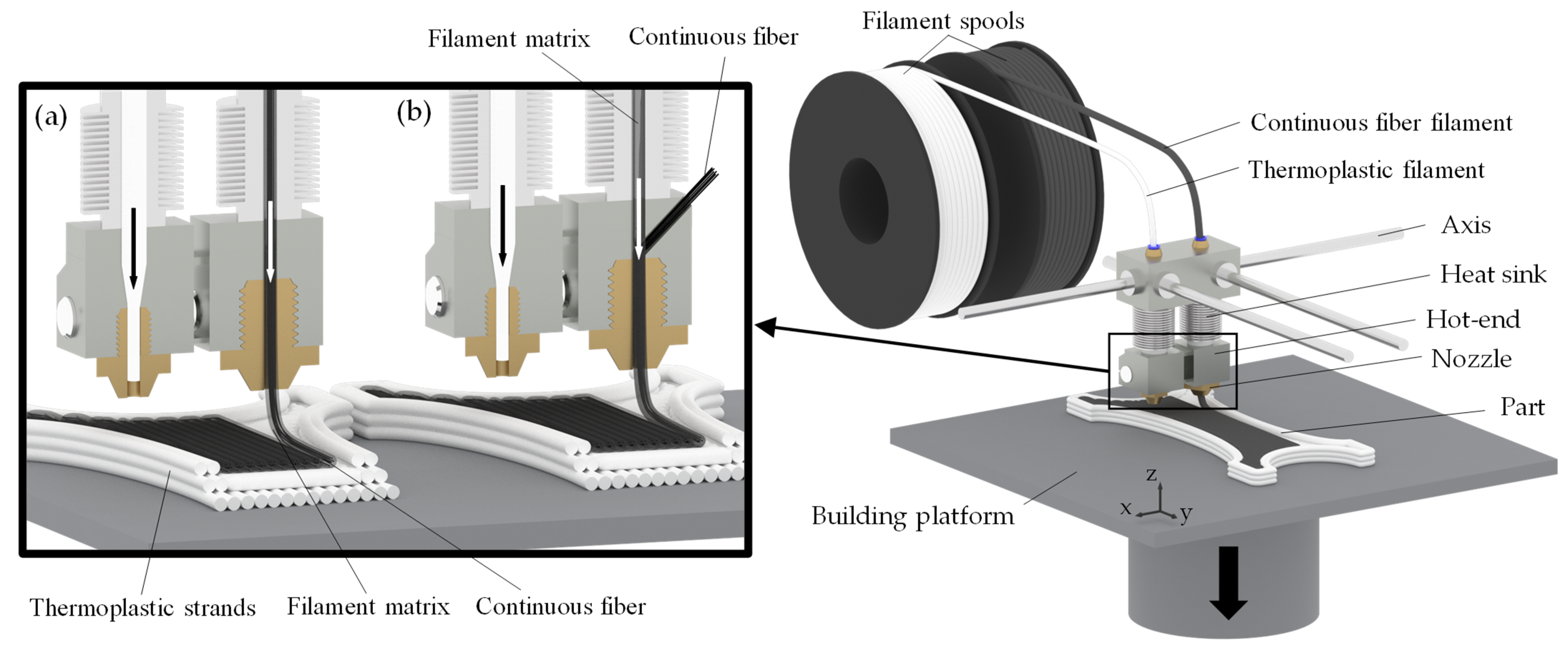
17]. The incorporation of continuous fibers can be achieved by two different methods. The first method is to merge the continuous fibers in the printhead with the surrounding thermoplastic matrix and then deposit them on the print bed (see
Figure 1a). The second is to use pre-impregnated continuous fiber filaments that are already embedded in a thermoplastic matrix and can be extruded immediately (see
Figure 1b) [
18,
19]. Commercial printing systems and corresponding fiber filaments are available for both approaches. In most systems, dual extruders are used, which allow both the application of continuous fiber-reinforced strands and the extrusion of pure thermoplastic material (see
Figure 1).
The mechanical properties of continuous fiber-reinforced parts depend on a large number of factors and parameters. In addition to the number and size of the defects and the interfacial adhesion, the selection of the fiber and matrix materials and their orientation in the part have a major influence on the mechanical properties [
6,
20]. Two of the biggest challenges in establishing continuous fiber extrusion in industrial applications are severe anisotropy and low print quality. Various research activities have investigated the damage mechanisms of printed composite parts. It was found that delamination between the layers or the fiber strands on the one hand and debonding, i.e., detachment of the matrix from the fibers, on the other hand, are the main types of failure [
21,
22,
23,
24]. In this context, Kabir et al. [
6] point out that another major challenge is the very limited choice of fiber and matrix materials with the associated limited adaptability to the load case at hand.
1.2. Hybrid Composites
Hybrid composites are increasingly being used in conventional fiber-plastic composites in order to improve and adapt the mechanical properties to the existing load case. These composites are characterized by the combination of different fiber materials in one part in order to achieve unique material properties that could not be achieved by using one fiber material [
25,
26,
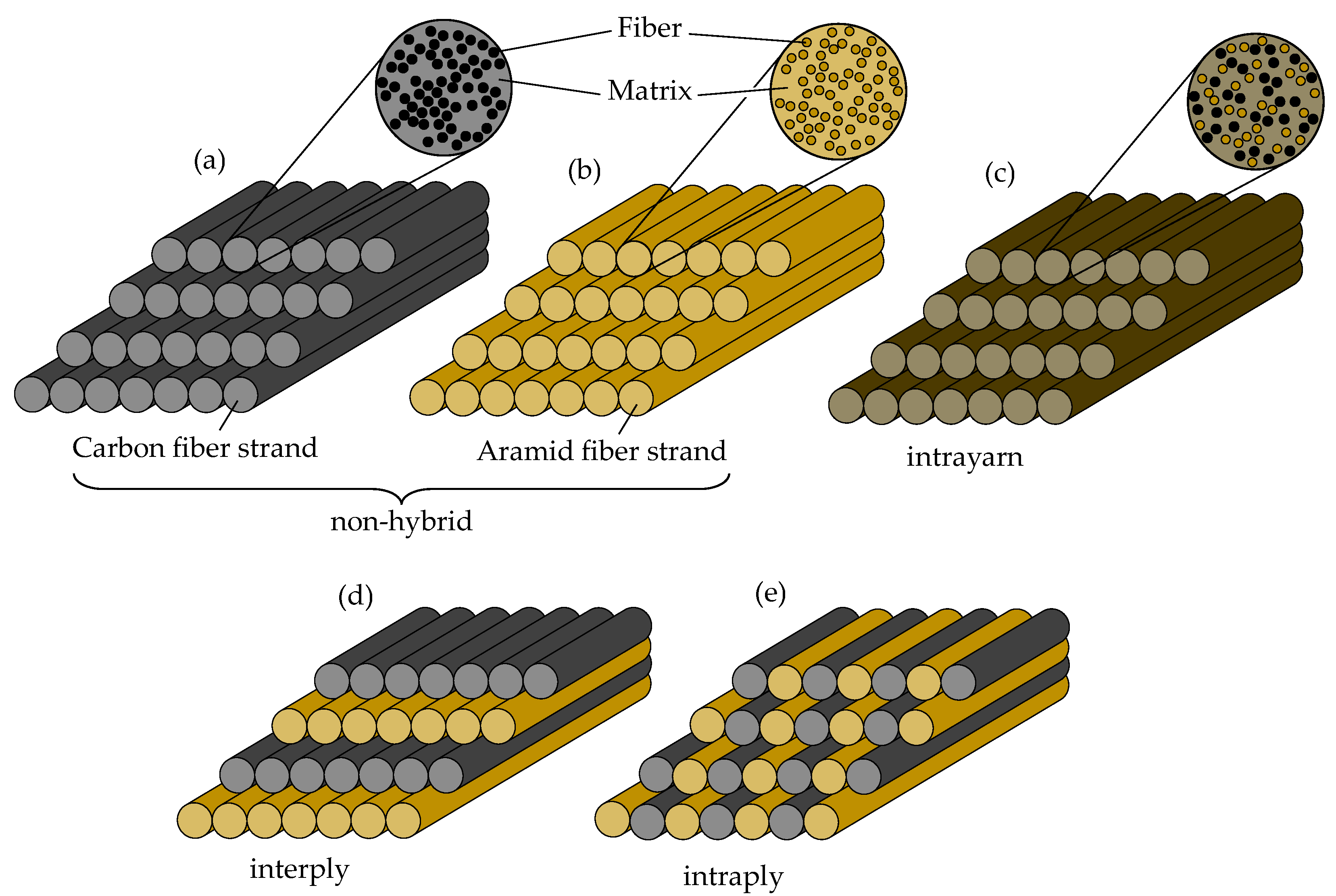
27]. In conventional manufacturing processes, the hybrid composites with continuous fibers are usually processed in the form of mats. There are different approaches for hybridization. According to Kretsis [
25] a distinction is made between the following approaches in this context:
Interply, alternating layers of different fiber materials;
Intraply, regular or irregular mixture of fiber materials on laminate level;
Intrayarn, mixed fiber materials on filament/roving level.
This categorization for conventional manufacturing processes of fiber-reinforced plastic composites can also be applied to additive manufacturing in the broadest sense (see
Figure 2). All three approaches can be implemented using continuous fiber-reinforced MEX. A mixed approach is also conceivable. The simplest approach is the alternating use of fiber materials between the layers (interply). The number of fiber cuts required per layer and the duration for a fiber or tool change are thus reduced to a minimum. However, this leads to a low dispersion of the different fiber materials. An approach involving the combination of different fiber materials in a layer plane can also be implemented. However, this is associated with increased production time and increased effort for path planning, but on the other hand leads to better adjustability of the mixing ratio—especially for thin, flat parts. Compared to the interply approach, the intraply approach leads to improved dispersion. An intrayarn approach requires the use of different fiber materials in one roving or fiber filament. Accordingly, this approach does not require tool changes or additional fiber cuts, but is associated with a loss of flexibility. Consequently, the mixing ratio for machine code generation cannot be set in a defined way, but depends on the ratio of the semi-finished product used. However, the best dispersion can be achieved with the help of the intrayarn approach [
28].
Research in the field of conventional hybrid composites has focused, among other things, on improving elongation at break or creating pseudoductile material behavior [
29,
30], improving fatigue strength [
31] and impact strength [
32,
33,
34] and implementing low-cost fibers [
35,
36]. Since the combination of different fiber materials in a part can also lead to a decrease in certain mechanical properties, a compromise in hybridization is necessary [
37,
38]. This implies an optimization criterion for the hybridization ratio that must be addressed in the design.
Carbon fiber-reinforced composites are characterized by comparatively high strength and stiffness with low elongation at break and impact strength [
39,
40]. Aramid fibers are therefore frequently added in hybrid composites with carbon fibers. Aramid fibers are usually added to carbon fiber-reinforced plastics due to their lower density and positive effects on impact strength [
32,
41]. It was shown by Pincheira et al. [
42], for example, that hybridization with aramid fibers in carbon fiber-reinforced composites resulted in an improvement in impact strength but a decrease in compressive and tensile strength and reduced stiffness. It was demonstrated by Ma et al. [
43] in quasi-static tests that hybrid carbon aramid composites resulted in increased energy absorption compared to carbon composites. Wan et al. [
44] observed a positive hybrid effect for braided carbon aramid hybrid composites in flexural strength and stiffness. No hybrid effect was observed for impact strength and shear strength. Positive hybrid effects on impact strength were also observed for carbon aramid composites by Marom et al. [
45].
In the context of continuous fiber-reinforced MEX, little attention has been paid to the use of hybrid composites. Quasi-static indentation tests on additively manufactured hybrid and non-hybrid parts using aramid and carbon fibers were performed by Wang et al. [
46]. A model of volume average stiffness and a model of hybrid effect were derived to predict the effects of hybridization on stiffness. Huang and Joosten [
30] conducted tensile tests on printed hybrids of polyamide 6 (nylon) with continuous fibers of glass and carbon. The focus was on investigating the pseudoductility of printed hybrid parts.
1.3. Hybrid Effect
Using the Rule of Hybrid Mixture (RoHM) equations, the properties of hybrid composites can be predicted based on the material properties of the individual composite systems [
47]. The assumption is that the hybrid system consists of two individual composite systems and that there are no interactions between the individual systems. The validity of the RoHM equations, especially for the Young’s modulus of unidirectionally reinforced composites, has been demonstrated in numerous studies [
48,
49,
50,
51,
52,
53]. The Young’s modulus of the hybrid composite
Ehyb can be determined with the following equation:
Vc is the relative volume fraction of a composite with one fiber material in the total volume and
Ec is the associated Young’s modulus. For hybrid composites with two composite systems, the following equation applies:
where
Vt is the total volume of the composite and
Vc1 or
Vc2 is the relative hybrid volume fraction of the first or second system, respectively. For the calculation of the Young’s modulus of a hybrid composite with two different fiber materials, taking equation 2 into account, the following equation is obtained:
Analogous to Equation (3), this can also be predicted for the determination of stress (see Equation (4) for an example) or impact strength at different mixing ratios [
37,
54,
55].
An approach often used in the literature in connection with the Rule of Hybrid Mixture is the distinction between a positive and negative hybrid effect. Here, an upward deviation of the experimentally determined material properties compared to the predicted RoHM values is considered a positive effect. A downward deviation is referred to as a negative hybrid effect. The hybrid effects can be determined for strength (
λσ), Young’s modulus (
λE) and impact strength (
λac) according to Equations (5)–(7).
For
λσ > 1,
λE > 1 and
λac > 1 the hybridization with the respective mixing ratio has a positive hybrid effect. For
λσ < 1,
λE < 1 and
λac < 1 it indicates a negative hybrid effect [
37,
56].
1.4. Aims and Scope
Approaches to improve the mechanical properties of fiber-reinforced thermoplastic parts manufactured with MEX, as well as their load case-specific adaptation, have been underrepresented in the literature so far. For the design of composite parts, the effects of hybridization on basic mechanical properties such as strength and stiffness under tensile or flexural stress must be known. These effects have not yet been studied for printed composites. This research gap shall be closed for hybrid composites of aramid and carbon fibers with different mixing ratios in this work. The specimens are fabricated in an interply approach, in which the fiber materials are varied layer by layer. Mechanical tests in the form of tensile, flexural and impact tests will be used to determine the effects of hybridizing carbon and aramid fibers with different mixing ratios. In addition, the microstructure of the hybrid specimens tested will be investigated in order to draw conclusions about the failure mechanisms. A Rule of Hybrid Mixture approach will be used to predict the effects of different mixing ratios based on the non-hybrid composites. The correlation of predicted and experimentally obtained values will be evaluated to confirm the reliability and transferability of the method to the additively manufactured composites.
2. Materials and Methods
In this section, the MEX system and the fiber and matrix materials used are first presented. In addition, the specimen design and fabrication will be outlined, and the test methods used will be described.
2.1. Setup and Materials
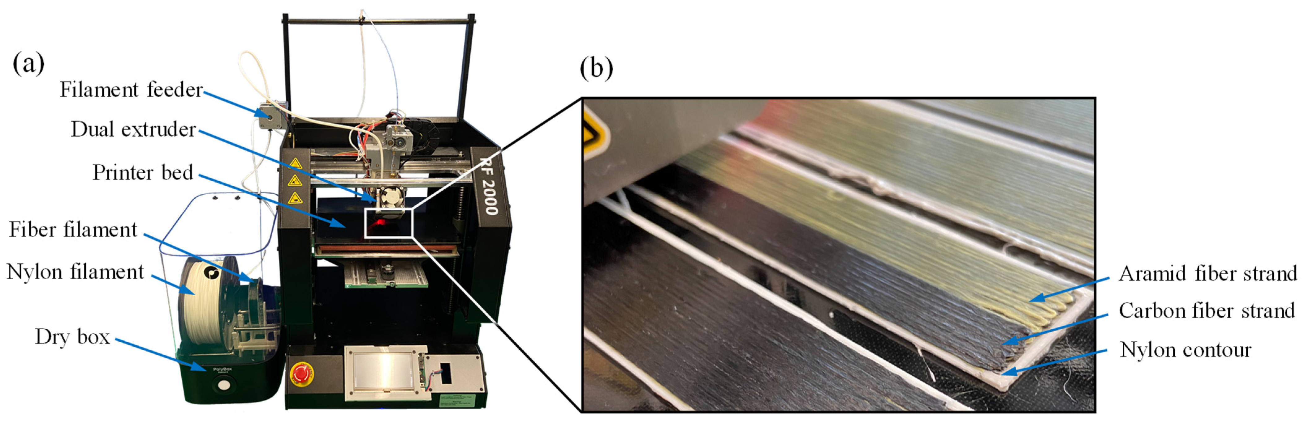
For specimen fabrication, a modified Renkforce RF2000 3D printer (Conrad Electronic SE, Hirschau, Germany) was used, which was equipped with a Markforged (Markforged, Inc., Watertown, MA, USA) printer head (see
Figure 3a). Polyamide 6 (PA6—“Nylon White”) was used as the matrix material and Markforged’s carbon continuous fiber filament (C-CFF) and aramid continuous fiber filament (A-CFF) were used as the fiber material (see
Figure 3b). The fiber content has been determined in various studies and is between 32.8% and 34.5% [
57,
58]. To avoid moisture absorption, all filaments were stored in an airtight PolyBoxTM (Polymaker B.V., Shanghai, China) with a humidity content <25% at a temperature between 20–25 °C (see
Figure 3a).
The process parameters listed in
Table 1 were determined in pretests and resulted in feasible processability and a minimum void fraction. Identical parameters were used for the carbon and aramid fiber layers.
2.2. Specimen Design and Fabrication
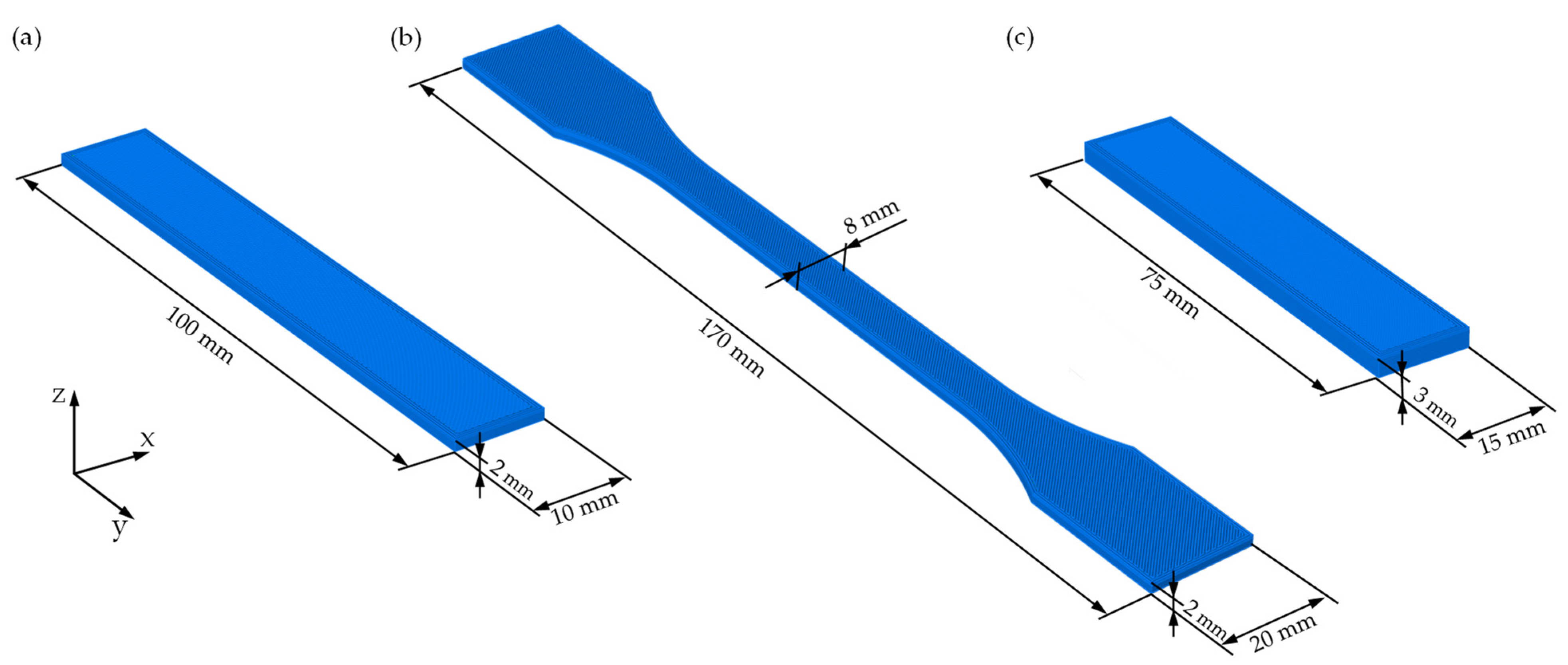
For mechanical characterization, tensile, flexural and impact tests were carried out. The dimensions of the specimens can be taken from
Figure 4. The machine code for fabricating the specimens was generated with an inhouse written slicing program in Rhinoceros 3D using the Grasshopper visual programming environment.
All specimens were manufactured with unidirectional fiber orientation in the longitudinal direction. The fiber volume fraction describes the percentage of fibers in the total volume of the part. For the calculation of the fiber volume content, an ideal specimen without voids was assumed. The fiber volume fractions can be calculated using the following equation:
where
Vf is the fiber volume fraction of the part,
vf is the fiber volume in the entire part and
Vt is the total volume of the specimen. For the calculation, a fiber volume content of the fiber filament of 34% was assumed. The fiber volume contents of the specimens are shown in
Table 2.
In order to determine and quantify the effect of different mixture ratios on the mechanical properties, the specimens were fabricated with different ratios of carbon fibers to aramid fibers. The ratios of all specimens of carbon fibers to aramid fibers were in percent 100/0, 70/30, 50/50, 30/70 and 0/100, resulting in 10 fiber layers for the tensile and flexural specimens and 20 fiber layers for the impact specimens (see
Figure 5). The fiber filament was changed between layers when necessary. In addition, the specimens were fabricated with two bottom and top layers of nylon.
2.3. Mechanical and Microstructural Characterization
Tensile, flexural and impact tests were carried out to determine the effects on the mechanical properties. The tensile and 3-point flexural tests were performed in accordance with DIN EN ISO 527-4 [
59] and DIN EN ISO 14125 [
60], respectively, on the Zwick/Roell Zmart.Pro BZ1 universal testing machine (Zwick Roell, Ulm, Germany). The machine force was determined by the load cell. The deformations during the tensile tests were measured using an extensometer with an initial gauge length of 80 mm. The deflections during the flexure tests were measured by the crosshead travel of the testing machine. A span of 80 mm was used for the flexural tests. For both tensile and flexural tests, a test speed of 2 mm/min was used. The tensile and flexural stresses, moduli and strains were calculated according to the specifications of the underlying standards [
59,
60]. The impact tests were carried out on the Zwick/Roell HIT25P pendulum impact tester (Zwick Roell, Ulm, Germany) in accordance with DIN EN ISO 179-1 [
61]. The Charpy impact strength was calculated according to the specifications of the calculated according to the underlying standard. All tests were performed under identical environmental conditions at a room temperature of 22 °C. Five specimens were fabricated and tested for each mixing ratio and test method.
For the investigation of the microstructure of the fracture surfaces, images were taken with a scanning electron microscope (SEM). A Zeiss Leo 1455VP scanning electron microscope (Carl Zeiss AG, Oberkochen, Germany) with an accelerating voltage of 5 kV and a working distance of 8–10 mm was used.
3. Results and Discussion
In this section, the results of the investigations are addressed. First, the results of the mechanical tests are presented. Then, the hybrid effect is described on the basis of the experimentally determined values. Finally, the failure mechanisms are described on the basis of analyses of the microstructure of the fracture surfaces.
3.1. Mechanical Properties
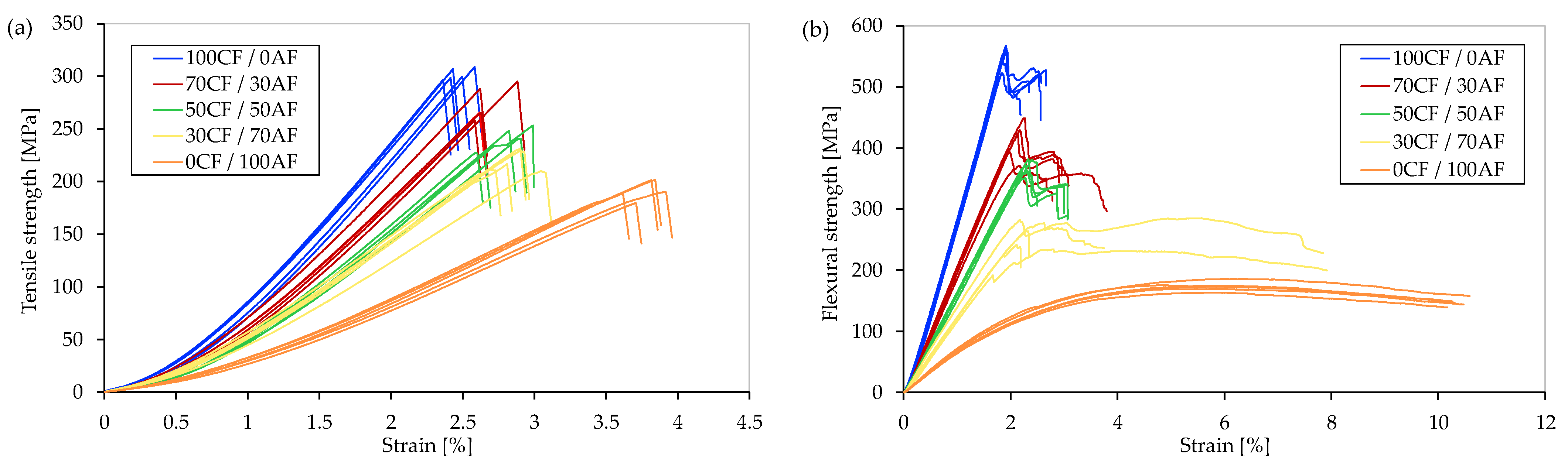
The mechanical properties of the printed hybrids were determined by tensile, flexural and impact tests. The stress-strain curves of the tensile and flexural tests are shown in
Figure 6.
The comparatively low tensile strengths compared to the flexural strengths are due, on the one hand, to the lower fiber volume content and, on the other hand, to the fiber orientation in the tensile specimens. Due to the contour-based fiber orientation, the fibers at the specimen fillets are not fully loaded in the longitudinal direction, which can lead to a reduction in strength. The results show that an increasing content of aramid in the specimens leads to a significant decrease in the mechanical properties under tensile and flexural loading. Both for tensile and flexural strengths and for Young’s and flexural moduli, the 100% carbon specimens show the highest measured values. This results from the higher strengths and stiffnesses of the carbon fibers compared to the aramid fibers. It can also be observed that the flexural strengths and stiffnesses decrease significantly more with increasing aramid content compared to the tensile strengths and stiffnesses. The largest strain rates are observed in 100% aramid specimens with a steep decrease in strain rates when hybridized with carbon fibers.
Despite hybridization, brittle fracture was observed in all tensile specimens without multiple fractures (see
Figure 6a). An increasing content of aramid fibers also leads to an increase of the strain rates in the carbon fiber-reinforced specimens. This could be due to the fact that damage evolution in the carbon fiber layers is limited by the adjacent, more ductile aramid fiber layers. Similar phenomena were also described for conventional composites with interply approach in [
37,
50,
62].
Multiple fractures were observed in the flexural tests of the specimens with high carbon fiber content, which can be attributed to failure of individual fiber layers at short time intervals (see
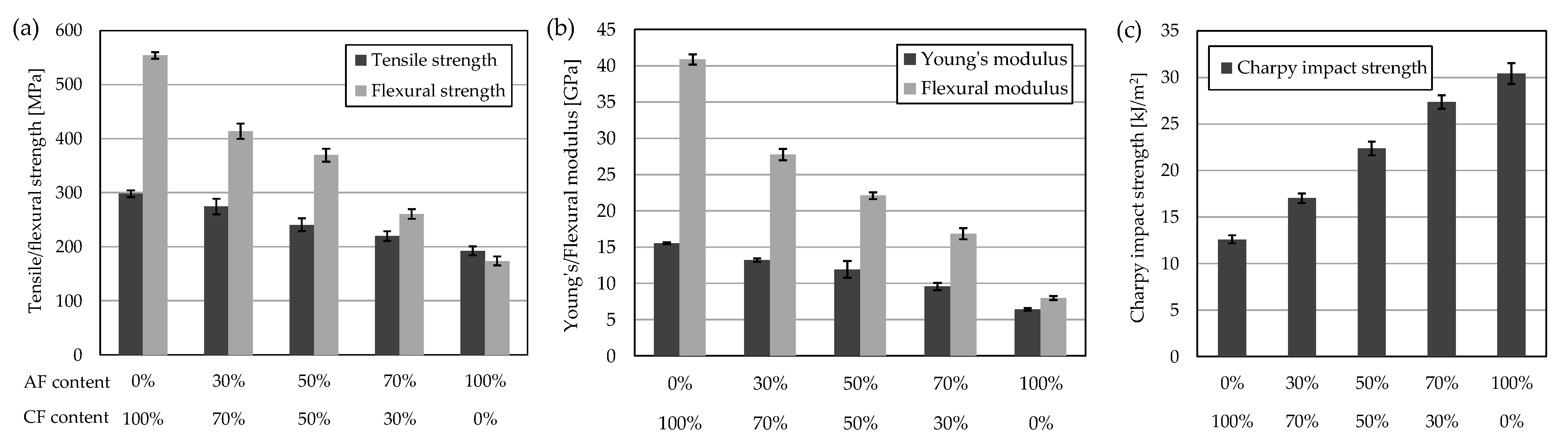
Figure 6b). The averaged results of the tensile, flexural and impact tests are shown with the corresponding standard deviations in
Figure 7. The experimental results show an approximately linear decrease or increase in the mechanical properties of the hybrid specimens. The 100% carbon specimens exhibit average tensile and flexural strengths of 297 MPa and 554 MPa, respectively. The aramid specimens, on the other hand, show tensile and flexural strengths of 192 MPa and 173 MPa, respectively, about 35% lower and 69% lower, respectively, compared with 100% carbon specimens. The tensile and flexural moduli of the 100% aramid composite are lower by a factor of 2.4 and 5.1, at 6.42 GPa and 7.97 GPa, respectively, compared with the pure carbon fiber-reinforced composites. In contrast, the Charpy impact strength increases significantly with increasing aramid content. The highest impact strength was measured for 100% aramid specimens, while the lowest impact strength was observed for 100% carbon specimens. The 100% aramid specimens exhibited a Charpy impact strength of 30.42 kJ/m
2, while the 100% carbon specimens exhibited a Charpy impact strength of only 12.60 kJ/m
2. This can be explained by the increased energy absorption capabilities of the aramid fibers. This observation was also made for conventionally manufactured hybrid carbon and aramid composites [
42,
45].
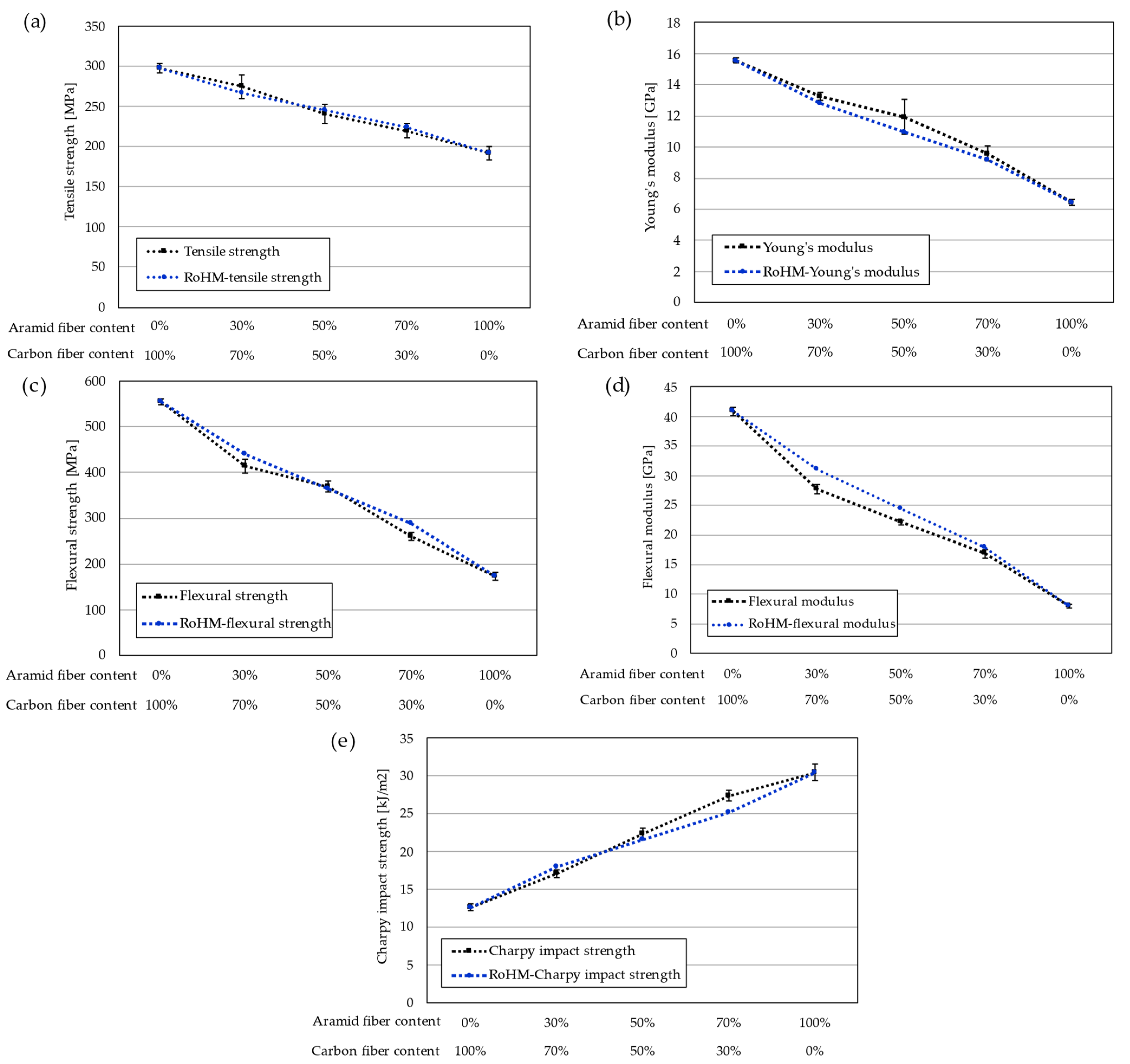
Figure 8 compares the experimentally determined mechanical properties with the values predicted by the RoHM equations. The calculated hybrid effects as a percentage are shown in
Table 3. Both positive and negative hybrid effects have been determined. From the values in
Table 3, it can be seen that the prediction of the RoHM equations calculated on the basis of the average values of the non-hybrid composite systems are able to predict the mechanical properties of the hybrid composites with high accuracy. The average deviation of all predicted values is about 5.6%, taking into account the comparatively small number of samples and the associated measurement uncertainty. The largest deviation, with about −10.5%, was determined for the flexural modulus with a mixing ratio of 70CF/30AF. No correlations can be observed between the hybrid effects in the tensile and flexural properties. In particular, +3.3%, +8.8% and +4.7% for the tensile modulus were entirely positive hybrid effects, while −10.5%, −9.5% and −5.6% for the flexural modulus were entirely negative hybrid effects. The flexural strengths also show higher negative hybrid effects compared to the tensile strengths. This could be explained by a high influence of the layer arrangement in the flexural specimens. While in the uniaxial tensile test all layers are approximately equally stressed, no homogeneous stress distribution occurs in the flexural test. Therefore, the mechanical properties in the flexural tests are more dependent on the layer configuration. Since the stress in the neutral line is zero, the fiber layers become increasingly important with increasing distance from it. Alternating layers with widely different strain rates, which are additionally subjected to different stresses across the cross-section, could increase delamination effects that reduce the stiffness and strength of the composite.
For the Charpy impact strengths, especially with increasing aramid content, positive hybrid effects of +4.0% for 50CF/50AF and +9.0% for 30CF/70AF were shown while a negative hybrid effect of −5.2% was observed at low aramid content of 30%. The negative hybrid effect for the 70CF/30AF specimens could be due to the two outer carbon fiber layers, since the outermost layers have the greatest influence on impact strength. This was also observed in a similar way by Marom et al. [
45], among others.
3.2. Damage and Failure Analysis
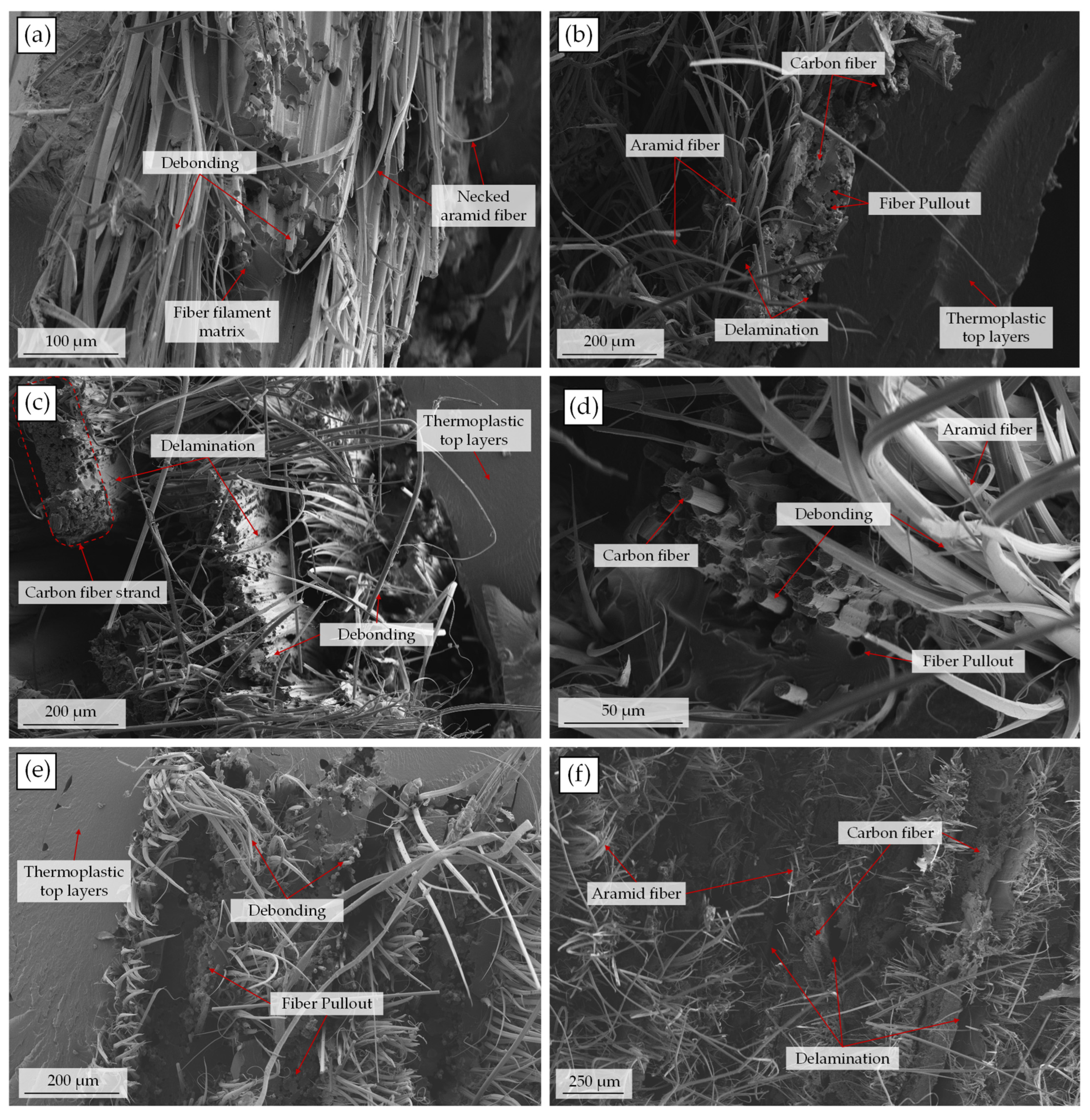
In order to draw conclusions on the main failure mechanisms and possible differences between the fiber types, the microstructure of the fracture surfaces was investigated. For this purpose, SEM images were taken of specimens with 50% relative fiber content of carbon and aramid, respectively. The fracture surfaces of specimens from each test method were examined. The images of the fracture surfaces are shown in
Figure 9.
The analyzed fracture surfaces of the different specimens show similar failure mechanisms. Differences with regards to the different test methods cannot be identified. However, the different fiber types can be clearly identified. The aramid fibers can be identified by the ductile fracture typical of aramid fibers with necked fibers (see, e.g.,
Figure 9a,d). The carbon fibers, on the other hand, exhibit brittle fracture surfaces. This is also consistent with the strongly different strain rates of the carbon and aramid fiber-reinforced specimens in the mechanical tests. Furthermore, the higher energy absorption and the resulting impact strength can be justified with increasing aramid content. In addition, the aramid fibers show more debonding, which was also observed by Wang et al. [
46]. This may indicate poorer impregnation of the aramid fibers. The ductile fractures and the significant difference in length compared to the carbon fibers may reinforce this impression.
Nevertheless, similar failure mechanisms can be identified for both the carbon and aramid fibers. For example, strong debonding occurs in all specimens. This can be seen from the numerous exposed fibers, which are surrounded by little or no matrix. This is more evident in the aramid fibers due to the large difference in length. In addition to exposed fibers, the carbon fiber layers also show vacancies caused by pulled-out fibers (see
Figure 9d,e). In addition, delamination can be seen on all fracture surfaces. Delamination indicates a low adhesion strength between the layers or between the fiber strands. This could be further promoted by the different elongation rates of the fibers in the layers. Debonding and delamination are among the main failure mechanisms in printed composites and have been widely reported in the literature [
21,
22,
23,
24].
Another aspect that stands out in the analysis of the fracture surfaces is the partially irregular distribution of the fibers in the surrounding matrix (see e.g.,
Figure 9a,d). This phenomenon occurs commonly in printed composites and is also described in [
63]. This could be due to the comparatively low fiber volume fraction of the fiber filaments (approx. 34%).
4. Conclusions and Outlook
In this work, additively manufactured hybrid composites with carbon and aramid fibers in a PA6 matrix and varying mixing ratios were investigated. The intention behind the use of hybrid composites is to improve or adjust mechanical properties. Tensile, flexural and impact tests were carried out to determine the effects of hybridization. Specimens were prepared with carbon to aramid mixing ratios of 100/0, 70/30, 50/50, 30/70 and 0/100. Based on the mechanical properties of the non-hybrid specimens, a Rule of Hybrid Mixture approach was followed to predict the mechanical properties at different mixing ratios. In addition, the microstructure of the fracture surfaces of the specimens was analyzed with SEM examinations.
The investigations have shown that hybrid composites of thermoplastics with continuous fiber reinforcement produced with MEX offer a possibility to influence the mechanical properties of the parts in the desired way. The material mixture of carbon and aramid fibers investigated showed a significant improvement in impact strength with increasing aramid fiber content. The tensile and flexural strengths as well as the stiffnesses, on the other hand, decreased with increasing aramid fiber content. The impact strength of additively manufactured carbon fiber-reinforced parts could thus be effectively improved by adding aramid fibers. However, this is accompanied by low strengths and stiffnesses of the composite. The application of the RoHM equations resulted in a good approximation to the experimentally determined values, with an average deviation of about 5.6% when the material properties were known for only one fiber material. The RoHM equations are therefore well suited to unidirectionally reinforced hybrid composites fabricated by MEX and can be used to predict the mechanical properties of hybrid parts. The damage mechanisms of printed hybrids are similar to those of non-hybrid printed composites. In particular, debonding and delamination occur as main damage mechanisms. Significant differences between the failure modes of the carbon and aramid fibers could not be found.
Implementation of the selected interply approach in existing printer systems is possible by adding an additional fiber extruder. It is also conceivable to change the fiber materials during the printing process. This also requires an adaptation of the slicing software. In the future, the use of prefabricated hybrid fiber filaments (intrayarn) should also be investigated. In particular, the improved dispersion and its influence on the mechanical properties are of interest. This approach could be implemented without changes to existing filament-based MEX-setups and the associated slicing software. In addition, further investigations should be carried out with other fiber materials and combinations. In addition to the established fiber materials, such as carbon, glass or aramid, natural fibers can also be implemented, which could reduce costs as well as improving the adjustability of the mechanical properties. In addition to the fiber material or the fiber combination, the fiber orientation and the layer configuration are also crucial. In this context, the high flexibility in strand deposition of MEX offers enormous potentials for local adaption of the mechanical properties. For this purpose, appropriate strategies and methods have to be developed which take into account the combination of different fiber materials.
Author Contributions
Conceptualization, T.H.; methodology, T.H.; software, T.H.; validation, T.H. and S.G.; formal analysis, T.H., S.K. and S.G.; design and manufacturing of the test specimens T.H.; investigation, T.H.; resources, T.H. and S.G.; data curation, T.H.; writing—original draft preparation, T.H.; writing—review and editing, S.K., S.G. and N.W.; visualization, T.H.; supervision, G.K., N.W. and T.V.; project administration, G.K., N.W. and T.V.; funding acquisition, G.K., N.W. and T.V. All authors have read and agreed to the published version of the manuscript.
Funding
Funded by the Ministry for Science and Culture of Lower Saxony (MWK)–School for Additive Manufacturing SAM (78904-63-3/19).
Institutional Review Board Statement
Not applicable.
Informed Consent Statement
Not applicable.
Data Availability Statement
The data presented in this study are available in the article.
Acknowledgments
We acknowledge support by the Open Access Publication Funds of Technische Universität Braunschweig.
Conflicts of Interest
The authors declare no conflict of interest.
References
- Gibson, I.; Rosen, D.; Stucker, B. Additive Manufacturing Technologies: 3D Printing, Rapid Prototyping and Direct Digital Manufacturing, 2nd ed.; Springer: Berlin/Heidelberg, Germany, 2015; ISBN 1493921126. [Google Scholar]
- Gebhardt, A. Additive Fertigungsverfahren: Additive Manufacturing und 3D-Drucken für Prototyping–Tooling–Produktion, 5th ed.; Hanser: München, Germany, 2016; ISBN 9783446444010. [Google Scholar]
- Haruna, A.; Jiang, P. A Design for Additive Manufacturing Framework: Product Function Integration and Structure Simplification. IFAC-Pap. 2020, 53, 77–82. [Google Scholar] [CrossRef]
- Tang, Y.; Yang, S.; Zhao, Y.F. Sustainable Design for Additive Manufacturing Through Functionality Integration and Part Consolidation. In Handbook of Sustainability in Additive Manufacturing: Volume 1, 1st ed.; Muthu, S.S., Savalani, M.M., Eds.; Springer: Singapore, 2016; pp. 101–144. ISBN 978-981-10-0547-3. [Google Scholar]
- Mazurchevici, A.; Nedelcu, D.; Popa, R. Additive manufacturing of composite materials by FDM technology: A review. Indian J. Eng. Mater. Sci. 2020, 27, 179–192. [Google Scholar]
- Kabir, S.M.F.; Mathur, K.; Seyam, A.-F.M. A critical review on 3D printed continuous fiber-reinforced composites: History, mechanism, materials and properties. Compos. Struct. 2020, 232, 111476. [Google Scholar] [CrossRef]
- Ngo, T.D.; Kashani, A.; Imbalzano, G.; Nguyen, K.T.; Hui, D. Additive manufacturing (3D printing): A review of materials, methods, applications and challenges. Compos. Part B Eng. 2018, 143, 172–196. [Google Scholar] [CrossRef]
- Mohan, N.; Senthil, P.; Vinodh, S.; Jayanth, N. A review on composite materials and process parameters optimisation for the fused deposition modelling process. Virtual Phys. Prototyp. 2017, 12, 47–59. [Google Scholar] [CrossRef]
- Naranjo-Lozada, J.; Ahuett-Garza, H.; Orta-Castañón, P.; Verbeeten, W.M.; Sáiz-González, D. Tensile properties and failure behavior of chopped and continuous carbon fiber composites produced by additive manufacturing. Addit. Manuf. 2019, 26, 227–241. [Google Scholar] [CrossRef]
- Blok, L.G.; Longana, M.L.; Yu, H.; Woods, B. An investigation into 3D printing of fibre reinforced thermoplastic composites. Addit. Manuf. 2018, 22, 176–186. [Google Scholar] [CrossRef]
- Le Duigou, A.; Barbé, A.; Guillou, E.; Castro, M. 3D printing of continuous flax fibre reinforced biocomposites for structural applications. Mater. Des. 2019, 180, 107884. [Google Scholar] [CrossRef]
- Goh, G.D.; Dikshit, V.; Nagalingam, A.P.; Goh, G.L.; Agarwala, S.; Sing, S.L.; Wei, J.; Yeong, W.Y. Characterization of mechanical properties and fracture mode of additively manufactured carbon fiber and glass fiber reinforced thermoplastics. Mater. Des. 2018, 137, 79–89. [Google Scholar] [CrossRef]
- Rijckaert, S.; Daelemans, L.; Cardon, L.; Boone, M.; van Paepegem, W.; Clerck, K.D. Continuous Fiber-Reinforced Aramid/PETG 3D-Printed Composites with High Fiber Loading through Fused Filament Fabrication. Polymers 2022, 14, 298. [Google Scholar] [CrossRef]
- Kuschmitz, S.; Schirp, A.; Busse, J.; Watschke, H.; Schirp, C.; Vietor, T. Development and Processing of Continuous Flax and Carbon Fiber-Reinforced Thermoplastic Composites by a Modified Material Extrusion Process. Materials 2021, 14, 2332. [Google Scholar] [CrossRef] [PubMed]
- Tian, X.; Liu, T.; Wang, Q.; Dilmurat, A.; Li, D.; Ziegmann, G. Recycling and remanufacturing of 3D printed continuous carbon fiber reinforced PLA composites. J. Clean. Prod. 2017, 142, 1609–1618. [Google Scholar] [CrossRef]
- Obande, W.; Ó Brádaigh, C.M.; Ray, D. Continuous fibre-reinforced thermoplastic acrylic-matrix composites prepared by liquid resin infusion—A review. Compos. Part B Eng. 2021, 215, 108771. [Google Scholar] [CrossRef]
- Zhang, H.; Liu, D.; Huang, T.; Hu, Q.; Lammer, H. Three-Dimensional Printing of Continuous Flax Fiber-Reinforced Thermoplastic Composites by Five-Axis Machine. Materials 2020, 13, 1678. [Google Scholar] [CrossRef]
- Hu, Q.; Duan, Y.; Zhang, H.; Liu, D.; Yan, B.; Peng, F. Manufacturing and 3D printing of continuous carbon fiber prepreg filament. J. Mater. Sci. 2018, 53, 1887–1898. [Google Scholar] [CrossRef]
- Prüß, H.; Vietor, T. Design for Fiber-Reinforced Additive Manufacturing. J. Mech. Des. 2015, 137, 111409. [Google Scholar] [CrossRef]
- Lupone, F.; Padovano, E.; Venezia, C.; Badini, C. Experimental Characterization and Modeling of 3D Printed Continuous Carbon Fibers Composites with Different Fiber Orientation Produced by FFF Process. Polymers 2022, 14, 426. [Google Scholar] [CrossRef]
- Tian, X.; Liu, T.; Yang, C.; Wang, Q.; Li, D. Interface and performance of 3D printed continuous carbon fiber reinforced PLA composites. Compos. Part A Appl. Sci. Manuf. 2016, 88, 198–205. [Google Scholar] [CrossRef]
- Luo, M.; Tian, X.; Shang, J.; Zhu, W.; Li, D.; Qin, Y. Impregnation and interlayer bonding behaviours of 3D-printed continuous carbon-fiber-reinforced poly-ether-ether-ketone composites. Compos. Part A Appl. Sci. Manuf. 2019, 121, 130–138. [Google Scholar] [CrossRef]
- Liu, T.; Tian, X.; Zhang, M.; Abliz, D.; Li, D.; Ziegmann, G. Interfacial performance and fracture patterns of 3D printed continuous carbon fiber with sizing reinforced PA6 composites. Compos. Part A Appl. Sci. Manuf. 2018, 114, 368–376. [Google Scholar] [CrossRef]
- Caminero, M.A.; Chacón, J.M.; García-Moreno, I.; Reverte, J.M. Interlaminar bonding performance of 3D printed continuous fibre reinforced thermoplastic composites using fused deposition modelling. Polym. Test. 2018, 68, 415–423. [Google Scholar] [CrossRef]
- Kretsis, G. A review of the tensile, compressive, flexural and shear properties of hybrid fibre-reinforced plastics. Composites 1987, 18, 13–23. [Google Scholar] [CrossRef]
- Chavhan, G.R.; Wankhade, L.N. Improvement of the mechanical properties of hybrid composites prepared by fibers, fiber-metals, and nano-filler particles—A review. Mater. Today Proc. 2020, 27, 72–82. [Google Scholar] [CrossRef]
- Priyanka, P.; Dixit, A.; Mali, H.S. High-Strength Hybrid Textile Composites with Carbon, Kevlar, and E-Glass Fibers for Impact-Resistant Structures. A Review. Mech. Compos. Mater. 2017, 53, 685–704. [Google Scholar] [CrossRef]
- Swolfs, Y.; McMeeking, R.M.; Verpoest, I.; Gorbatikh, L. The effect of fibre dispersion on initial failure strain and cluster development in unidirectional carbon/glass hybrid composites. Compos. Part A Appl. Sci. Manuf. 2015, 69, 279–287. [Google Scholar] [CrossRef]
- Czél, G.; Wisnom, M.R. Demonstration of pseudo-ductility in high performance glass/epoxy composites by hybridisation with thin-ply carbon prepreg. Compos. Part A Appl. Sci. Manuf. 2013, 52, 23–30. [Google Scholar] [CrossRef]
- Huang, C.; Joosten, M.W. 3D printed continuous fibre-reinforced composites: Design and characterisation of advanced pseudo-ductile hybrid laminates. Compos. Part A Appl. Sci. Manuf. 2021, 146, 106403. [Google Scholar] [CrossRef]
- Dickson, R.F.; Fernando, G.; Adam, T.; Reiter, H.; Harris, B. Fatigue behaviour of hybrid composites. J. Mater. Sci. 1989, 24, 227–233. [Google Scholar] [CrossRef]
- Gustin, J.; Joneson, A.; Mahinfalah, M.; Stone, J. Low velocity impact of combination Kevlar/carbon fiber sandwich composites. Compos. Struct. 2005, 69, 396–406. [Google Scholar] [CrossRef]
- Hosur, M.V.; Adbullah, M.; Jeelani, S. Studies on the low-velocity impact response of woven hybrid composites. Compos. Struct. 2005, 67, 253–262. [Google Scholar] [CrossRef]
- Dorey, G.; Sidey, G.R.; Hutchings, J. Impact properties of carbon fibre/Kevlar 49 fibre hydrid composites. Composites 1978, 9, 25–32. [Google Scholar] [CrossRef]
- Giancaspro, J.W.; Papakonstantinou, C.G.; Balaguru, P.N. Flexural Response of Inorganic Hybrid Composites With E-Glass and Carbon Fibers. J. Eng. Mater. Technol. 2010, 132, 021005. [Google Scholar] [CrossRef]
- Mansor, M.R.; Sapuan, S.M.; Zainudin, E.S.; Nuraini, A.A.; Hambali, A. Hybrid natural and glass fibers reinforced polymer composites material selection using Analytical Hierarchy Process for automotive brake lever design. Mater. Des. 2013, 51, 484–492. [Google Scholar] [CrossRef]
- Rajpurohit, A.; Joannès, S.; Singery, V.; Sanial, P.; Laiarinandrasana, L. Hybrid Effect in In-Plane Loading of Carbon/Glass Fibre Based Inter- and Intraply Hybrid Composites. J. Compos. Sci. 2020, 4, 6. [Google Scholar] [CrossRef]
- Ab Ghani, A.F. Hybrid Carbon/Glass Fiber Reinforced Polymer; A Frontier Material for Aerospace Industry: A Review on Mechanical Properties Enhancement. Curr. Sci. Technol. 2021, 1, 41–51. [Google Scholar] [CrossRef]
- Schürmann, H. Konstruieren mit Faser-Kunststoff-Verbunden, 2., Bearbeitete und erweiterte Auflage; Springer: Berlin/Heidelberg, Germany, 2007; ISBN 9783540721901. [Google Scholar]
- Rahmani, H.; Najafi, S.H.M.; Ashori, A. Mechanical performance of epoxy/carbon fiber laminated composites. J. Reinf. Plast. Compos. 2014, 33, 733–740. [Google Scholar] [CrossRef]
- Valença, S.L.; Griza, S.; de Oliveira, V.G.; Sussuchi, E.M.; de Cunha, F.G.C. Evaluation of the mechanical behavior of epoxy composite reinforced with Kevlar plain fabric and glass/Kevlar hybrid fabric. Compos. Part B Eng. 2015, 70, 1–8. [Google Scholar] [CrossRef]
- Pincheira, G.; Canales, C.; Medina, C.; Fernández, E.; Flores, P. Influence of aramid fibers on the mechanical behavior of a hybrid carbon–aramid–reinforced epoxy composite. Proc. Inst. Mech. Eng. Part L J. Mater. Des. Appl. 2018, 232, 58–66. [Google Scholar] [CrossRef]
- Ma, Y.; Sugahara, T.; Yang, Y.; Hamada, H. A study on the energy absorption properties of carbon/aramid fiber filament winding composite tube. Compos. Struct. 2015, 123, 301–311. [Google Scholar] [CrossRef]
- Wan, Y.Z.; Chen, G.C.; Huang, Y.; Li, Q.Y.; Zhou, F.G.; Xin, J.Y.; Wang, Y.L. Characterization of three-dimensional braided carbon/Kevlar hybrid composites for orthopedic usage. Mater. Sci. Eng. A 2005, 398, 227–232. [Google Scholar] [CrossRef]
- Marom, G.; Drukker, E.; Weinberg, A.; Banbaji, J. Impact behaviour of carbon/Kevlar hybrid composites. Composites 1986, 17, 150–153. [Google Scholar] [CrossRef]
- Wang, K.; Li, S.; Wu, Y.; Rao, Y.; Peng, Y. Simultaneous reinforcement of both rigidity and energy absorption of polyamide-based composites with hybrid continuous fibers by 3D printing. Compos. Struct. 2021, 267, 113854. [Google Scholar] [CrossRef]
- Friedrich, K.; Fakirov, S.; Zhang, Z. Polymer Composites: From Nano-to Macro-Scale; Springer: New York, NY, USA, 2005; ISBN 978-0-387-24176-0. [Google Scholar]
- Ikbal, H.; Wang, Q.; Azzam, A.; Li, W. Effect of hybrid ratio and laminate geometry on compressive properties of carbon/glass hybrid composites. Fibers Polym. 2016, 17, 117–129. [Google Scholar] [CrossRef]
- Zhang, J.; Chaisombat, K.; He, S.; Wang, C.H. Hybrid composite laminates reinforced with glass/carbon woven fabrics for lightweight load bearing structures. Mater. Des. 2012, 36, 75–80. [Google Scholar] [CrossRef]
- Pandya, K.S.; Veerraju, C.; Naik, N.K. Hybrid composites made of carbon and glass woven fabrics under quasi-static loading. Mater. Des. 2011, 32, 4094–4099. [Google Scholar] [CrossRef]
- Le Guen, M.J.; Newman, R.H.; Fernyhough, A.; Emms, G.W.; Staiger, M.P. The damping–modulus relationship in flax–carbon fibre hybrid composites. Compos. Part B Eng. 2016, 89, 27–33. [Google Scholar] [CrossRef]
- Mirbagheri, J.; Tajvidi, M.; Hermanson, J.C.; Ghasemi, I. Tensile properties of wood flour/kenaf fiber polypropylene hybrid composites. J. Appl. Polym. Sci. 2007, 105, 3054–3059. [Google Scholar] [CrossRef]
- Fischer, S.; Marom, G. The flexural behaviour of aramid fibre hybrid composite materials. Compos. Sci. Technol. 1987, 28, 291–314. [Google Scholar] [CrossRef]
- Swolfs, Y.; Geboes, Y.; Gorbatikh, L.; Pinho, S.T. The importance of translaminar fracture toughness for the penetration impact behaviour of woven carbon/glass hybrid composites. Compos. Part A Appl. Sci. Manuf. 2017, 103, 1–8. [Google Scholar] [CrossRef]
- Onal, L.; Adanur, S. Effect of Stacking Sequence on the Mechanical Properties of Glass–Carbon Hybrid Composites before and after Impact. J. Ind. Text. 2002, 31, 255–271. [Google Scholar] [CrossRef]
- Haneefa, A.; Bindu, P.; Aravind, I.; Thomas, S. Studies on Tensile and Flexural Properties of Short Banana/Glass Hybrid Fiber Reinforced Polystyrene Composites. J. Compos. Mater. 2008, 42, 1471–1489. [Google Scholar] [CrossRef]
- Van Der Klift, F.; Koga, Y.; Todoroki, A.; Ueda, M.; Hirano, Y.; Matsuzaki, R. 3D Printing of Continuous Carbon Fibre Reinforced Thermo-Plastic (CFRTP) Tensile Test Specimens. OJCM 2016, 6, 18–27. [Google Scholar] [CrossRef]
- Dutra, T.A.; Ferreira, R.T.L.; Resende, H.B.; Guimarães, A. Mechanical characterization and asymptotic homogenization of 3D-printed continuous carbon fiber-reinforced thermoplastic. J. Braz. Soc. Mech. Sci. Eng. 2019, 41, 1–15. [Google Scholar] [CrossRef]
- Deutsches Institut für Normung e. V. EN ISO 527-4: Kunststoffe–Bestimmung der Zugeigenschaften–Teil 4; Prüfbedingungen für Isotrop und Anisotrop Faserverstärkte Kunststoffverbundwerkstoffe; Beuth Verlag GmbH: Berlin, Germany, 1997. [Google Scholar]
- Deutsches Institut für Normung e. V. DIN EN ISO 14125: Faserverstärkte Kunststoffe—Bestimmung der Biegeeigenschaften; Beuth Verlag GmbH: Berlin, Germany, 2011. [Google Scholar]
- Deutsches Institut für Normung e. V. Kunststoffe–DIN EN ISO 179-1: Bestimmung der Charpy-Schlageigenschaften–Teil 1: Nicht Instrumentierte Schlagzähigkeitsprüfung; Beuth Verlag GmbH: Berlin, Germany, 2010. [Google Scholar]
- Swolfs, Y.; Gorbatikh, L.; Verpoest, I. Fibre hybridisation in polymer composites: A review. Compos. Part A Appl. Sci. Manuf. 2014, 67, 181–200. [Google Scholar] [CrossRef]
- Chabaud, G.; Castro, M.; Denoual, C.; Le Duigou, A. Hygromechanical properties of 3D printed continuous carbon and glass fibre reinforced polyamide composite for outdoor structural applications. Addit. Manuf. 2019, 26, 94–105. [Google Scholar] [CrossRef]
| Publisher’s Note: MDPI stays neutral with regard to jurisdictional claims in published maps and institutional affiliations. |
© 2022 by the authors. Licensee MDPI, Basel, Switzerland. This article is an open access article distributed under the terms and conditions of the Creative Commons Attribution (CC BY) license (https://creativecommons.org/licenses/by/4.0/).


 ,
, 


