
Effect of x on the Electrochemical Performance of Two-Layered Cathode Materials xLi2MnO3–(1−x)LiNi0.5Mn0.5O2

 , ,
, ,
Abstract
:1. Introduction
2. Experimental
2.1. Synthesis of Precursor
2.2. Synthesis of xLi2MnO3–(1−x)LiNi0.5Mn0.5O2 Powder
2.3. Electrochemical Coin Cell Fabrication
2.4. Characterization Techniques
3. Results and Discussion
4. Conclusions
Author Contributions
Funding
Data Availability Statement
Acknowledgments
Conflicts of Interest
References
- Ghosh, S.; Bhattacharjee, U.; Bhowmik, S.; Martha, D.; Surendra, K. A Review on High-Capacity and High-Voltage Cathodes for Next-Generation Lithium-ion Batteries. J. Energy Power Technol. 2022, 4, 1–59. [Google Scholar] [CrossRef]
- Rojas-Flores, S.; Pérez-Delgado, O.; Nazario-Naveda, R.; Rojales-Alfaro, H.; Benites, S.M.; La Cruz-Noriega, D.; Otiniano, N.M. Potential Use of Papaya Waste as a Fuel for Bioelectricity Generation. Processes 2021, 9, 1799. [Google Scholar] [CrossRef]
- Segundo, R.F.; La Cruz-Noriega, D.; Milly Otiniano, N.; Benites, S.M.; Esparza, M.; Nazario-Naveda, R. Use of Onion Waste as Fuel for the Generation of Bioelectricity. Molecules 2022, 27, 625. [Google Scholar] [CrossRef] [PubMed]
- Nazario-Naveda, R.; Benites, S.M. Sugar Industry Waste for Bioelectricity Generation. Environ. Res. Eng. Manag. 2021, 77, 15–22. [Google Scholar] [CrossRef]
- Segundo, R.F.; Renny, N.N.; Moises, G.C.; Daniel, D.N.; Natalia, D.D.; Karen, V.R. Generation of Bioelectricity from Organic Fruit Waste. Environ. Res. Eng. Manag. 2021, 77, 6–14. [Google Scholar] [CrossRef]
- Hayner, C.M.; Zhao, X.; Kung, H.H. Materials for rechargeable lithium-ion batteries. Annu. Rev. Chem. Biomol. Eng. 2012, 3, 445–471. [Google Scholar] [CrossRef]
- Konishi, H.; Hirano, T.; Takamatsu, D.; Gunji, A.; Feng, X.; Furutsuki, S.; Takahashi, S.; Terada, S. Potential hysteresis between charge and discharge reactions in Li1.2Ni0.13Mn0.54Co0.13O2 for lithium ion batteries. Solid State Ion. 2017, 300, 120–127. [Google Scholar] [CrossRef]
- Konishi, H.; Hirano, T.; Takamatsu, D.; Gunji, A.; Feng, X.; Furutsuki, S.; Okumura, T.; Terada, S.; Tamura, K. Mechanisms responsible for two possible electrochemical reactions in Li1.2Ni0.13Mn0.54Co0.13O2 used for lithium ion batteries. J. Solid State Chem. 2018, 258, 225–231. [Google Scholar] [CrossRef]
- Luo, K.; Roberts, M.R.; Guerrini, N.; Tapia-Ruiz, N.; Hao, R.; Massel, F.; Pickup, D.M.; Ramos, S.; Liu, Y.S.; Guo, J.; et al. Anion redox chemistry in the cobalt free 3d transition metal oxide intercalation electrode Li[Li0.2Ni0.2Mn0.6]O2. J. Am. Chem. Soc. 2016, 138, 11211–11218. [Google Scholar] [CrossRef] [Green Version]
- Nisa, S.S.; Rahmawati, M.; Yudha, C.S.; Nilasary, H.; Nursukatmo, H.; Oktaviano, H.S.; Muzayanha, S.U.; Purwanto, A. A Fast Approach to Obtain Layered Transition-Metal Cathode Material for Rechargeable Batteries. Batteries 2022, 8, 4. [Google Scholar] [CrossRef]
- Klink, J.; Hebenbrock, A.; Grabow, J.; Orazov, N.; Nylén, U.; Benger, R.; Beck, H.-P. Comparison of Model-Based and Sensor-Based Detection of Thermal Runaway in Li-Ion Battery Modules for Automotive Application. Batteries 2022, 8, 34. [Google Scholar] [CrossRef]
- Xu, B.; Qian, D.; Wang, Z.; Meng, Y.S. Recent progress in cathode materials research for advanced lithium ion batteries. Mater. Sci. Eng. R Rep. 2012, 73, 51–65. [Google Scholar] [CrossRef]
- Yu, H.; Zhou, H. High-energy cathode materials (Li2MnO3–LiMO2) for lithium-ion batteries. J. Phys. Chem. Lett. 2013, 4, 1268–1280. [Google Scholar] [CrossRef] [PubMed]
- Konishi, H.; Hirano, T.; Takamatsu, D.; Gunji, A.; Feng, X.; Furutsuki, S.; Okumura, T.; Terada, S. Suppression of potential hysteresis between charge and discharge reactions in lithium-rich layer-structured cathode material by increasing nickel/manganese ratio. Solid State Ion. 2017, 308, 84–89. [Google Scholar] [CrossRef]
- Hou, X.; Wang, Y.; Song, J.; Gu, H.; Guo, R.; Liu, W.; Mao, Y.; Xie, J. Electrochemical behavior of Mn-based Li-rich cathode material Li1.15Ni0.17Co0.11Mn0.57O2 fluorinated by NH4F. Solid State Ion. 2018, 325, 1–6. [Google Scholar] [CrossRef]
- Li, Y.C.; Xiang, W.; Wu, Z.G.; Xu, C.L.; Xu, Y.D.; Xiao, Y.; Yang, Z.G.; Wu, C.J.; Lv, G.P.; Guo, X.D. Construction of homogeneously Al3+ doped Ni rich Ni-Co-Mn cathode with high stable cycling performance and storage stability via scalable continuous precipitation. Electrochim. Acta 2018, 291, 84–94. [Google Scholar] [CrossRef]
- Wang, C.C.; Lin, Y.C.; Chiu, K.F. Alleviation of voltage fade of lithium-rich layered oxide cathodes of Li-ion battery by incorporation of Cr. J. Alloy. Compd. 2017, 721, 600–608. [Google Scholar] [CrossRef]
- Zou, T.; Qi, W.; Liu, X.; Wu, X.; Fan, D.; Guo, S.; Wang, L. Improvement of the electrochemical performance of Li1.2Ni0.13Co0.13Mn0.54O2 cathode material by Al2O3 surface coating. J. Electroanal. Chem. 2020, 859, 113845. [Google Scholar] [CrossRef]
- Zhong, J.; Yang, Z.; Yu, Y.; Liu, Y.; Li, J.; Kang, F. Surface substitution of polyanion to improve structure stability and electrochemical properties of lithium-rich layered cathode oxides. Appl. Surf. Sci. 2020, 512, 145741. [Google Scholar] [CrossRef]
- Kim, D.; Sandi, G.; Croy, J.R.; Gallagher, K.G.; Kang, S.H.; Lee, E.; Slater, M.D.; Johnson, C.S.; Thackeray, M.M. Composite layered-layered-spinel cathode structures for lithium-ion batteries. J. Electrochem. Soc. 2012, 160, A31. [Google Scholar] [CrossRef]
- Xiao, L.; Xiao, J.; Yu, X.; Yan, P.; Zheng, J.; Engelhard, M.; Bhattacharya, P.; Wang, C.; Yang, X.Q.; Zhang, J.G. Effects of structural defects on the electrochemical activation of Li2MnO3. Nano Energy 2015, 16, 143–151. [Google Scholar] [CrossRef] [Green Version]
- Zhang, K.; Li, B.; Zuo, Y.; Song, J.; Shang, H.; Ning, F.; Xia, D. Voltage decay in layered Li-rich Mn-based cathode materials. Electrochem. Energy Rev. 2019, 2, 606–623. [Google Scholar] [CrossRef]
- Baggetto, L.; Dudney, N.J.; Veith, G.M. Surface chemistry of metal oxide coated lithium manganese nickel oxide thin film cathodes studied by XPS. Electrochim. Acta 2013, 90, 135–147. [Google Scholar] [CrossRef]
- Zhou, D.; Liu, R.; He, Y.B.; Li, F.; Liu, M.; Li, B.; Yang, Q.H.; Cai, Q.; Kang, F. SiO2 hollow nanosphere-based composite solid electrolyte for lithium metal batteries to suppress lithium dendrite growth and enhance cycle life. Adv. Energy Mater. 2016, 6, 1502214. [Google Scholar] [CrossRef]
- Shojan, J.; Chitturi, V.R.; Torres, L.; Singh, G.; Katiyar, R.S. Lithium-ion battery performance of layered 0.3Li2MnO3–0.7LiNi0.5Mn0.5O2 composite cathode prepared by co-precipitation and sol–gel methods. Mater. Lett. 2013, 104, 57–60. [Google Scholar] [CrossRef]
- Xiang, Y.; Jiang, Y.; Liu, S.; Wu, J.; Liu, Z.; Zhu, L.; Xiong, L.; He, Z.; Wu, X. Improved electrochemical performance of 0.5Li2MnO3-0.5LiNi0.5Mn0.5O2 cathode materials for lithium ion batteries synthesized by ionic-liquid-assisted hydrothermal method. Front. Chem. 2020, 8, 729. [Google Scholar] [CrossRef]
- Bettge, M.; Li, Y.; Sankaran, B.; Rago, N.D.; Spila, T.; Haasch, R.T.; Petrov, I.; Abraham, D.P. Improving high-capacity Li1.2Ni0.15Mn0.55Co0.1O2-based lithium-ion cells by modifiying the positive electrode with alumina. J. Power Sources 2013, 233, 346–357. [Google Scholar] [CrossRef]
- Klein, A.; Axmann, P.; Yada, C.; Wohlfahrt-Mehrens, M. Improving the cycling stability of Li2MnO3 by surface treatment. J. Power Sources 2015, 288, 302–307. [Google Scholar] [CrossRef]
- Lin, J.; Mu, D.; Jin, Y.; Wu, B.; Ma, Y.; Wu, F. Li-rich layered composite Li[Li0.2Ni0.2Mn0.6]O2 synthesized by a novel approach as cathode material for lithium ion battery. J. Power Sources 2013, 230, 76–80. [Google Scholar] [CrossRef]
- Wu, Q.; Zhang, X.; Sun, S.; Wan, N.; Pan, D.; Bai, Y.; Zhu, H.; Hu, Y.S.; Dai, S. Improved electrochemical performance of spinel LiMn1.5Ni0.5O4 through MgF2 nano-coating. Nanoscale 2015, 7, 15609–15617. [Google Scholar] [CrossRef]
- Song, L.; Tang, Z.; Chen, Y.; Xiao, Z.; Li, L.; Zheng, H.; Li, B.; Liu, Z. Structural analysis of layered Li2MnO3–LiMO2 (M= Ni1/3Mn1/3Co1/3, Ni1/2Mn1/2) cathode materials by Rietveld refinement and first-principles calculations. Ceram. Int. 2016, 42, 8537–8544. [Google Scholar] [CrossRef]
- Redel, K.; Kulka, A.; Plewa, A.; Molenda, J. High-performance Li-rich layered transition metal oxide cathode materials for Li-ion batteries. J. Electrochem. Soc. 2019, 166, A5333. [Google Scholar] [CrossRef]
- Gabrielli, G.; Marinaro, M.; Mancini, M.; Axmann, P.; Wohlfahrt-Mehrens, M. A new approach for compensating the irreversible capacity loss of high-energy Si/C|LiNi0.5Mn1.5O4 lithium-ion batteries. J. Power Sources 2017, 351, 35–44. [Google Scholar] [CrossRef]
- Hua, W.; Chen, M.; Schwarz, B.; Knapp, M.; Bruns, M.; Barthel, J.; Yang, X.; Sigel, F.; Azmi, R.; Senyshyn, A.; et al. Lithium/Oxygen Incorporation and Microstructural Evolution during Synthesis of Li-Rich Layered Li[Li0.2Ni0.2Mn0.6]O2 Oxides. Adv. Energy Mater. 2019, 9, 1803094. [Google Scholar] [CrossRef]
- Konishi, H.; Hirano, T.; Takamatsu, D.; Okumura, T. Electrochemical reaction mechanism of two components in xLi2MnO3–(1–x)LiNi0.5Mn0.5O2 and effect of x on the electrochemical performance in lithium ion battery. J. Electroanal. Chem. 2020, 873, 114402. [Google Scholar] [CrossRef]
- Jiang, Y.; Yang, Z.; Luo, W.; Hu, X.; Huang, Y. Hollow 0.3Li2MnO3-0.7LiNi0.5Mn0.5O2 microspheres as a high-performance cathode material for lithium–ion batteries. Phys. Chem. Chem. Phys. 2013, 15, 2954–2960. [Google Scholar] [CrossRef] [PubMed]
- Xiang, Y.; Li, J.; Liao, Q.; Wu, X. Morphology and particle growth of Mn-based carbonate precursor in the presence of ethylene glycol for high-capacity Li-rich cathode materials. Ionics 2019, 25, 81–87. [Google Scholar] [CrossRef]
- Guo, J.; Deng, Z.; Yan, S.; Lang, Y.; Gong, J.; Wang, L.; Liang, G. Preparation and electrochemical performance of LiNi0. 5Mn1. 5O4 spinels with different particle sizes and surface orientations as cathode materials for lithium-ion battery. J. Mater. Sci. 2020, 55, 13157–13176. [Google Scholar] [CrossRef]
- Singh, G.; West, W.C.; Soler, J.; Katiyar, R.S. In situ Raman spectroscopy of layered solid solution Li2MnO3–LiMO2 (M = Ni, Mn, Co). J. Power Sources 2012, 218, 34–38. [Google Scholar] [CrossRef]
- Liu, C.; Wu, M.; Zong, Y.; Zhang, L.; Yang, Y.; Yang, G. Synthesis and structural properties of xLi2MnO3-(1-x)LiNi0.5Mn0.5O2 single crystals towards enhancing reversibility for lithium-ion battery/pouch cells. J. Alloy. Compd. 2019, 770, 490–499. [Google Scholar] [CrossRef]
- Xiang, Y.; Sun, Z.; Li, J.; Wu, X.; Liu, Z.; Xiong, L.; Yin, Z. Improved electrochemical performance of Li1.2Ni0.2Mn0.6O2 cathode material for lithium ion batteries synthesized by the polyvinyl alcohol assisted sol-gel method. Ceram. Int. 2017, 43, 2320–2324. [Google Scholar] [CrossRef]
- Yu, C.; Li, G.; Guan, X.; Zheng, J.; Li, L. Composites Li1+xMn0.5+0.5 xNi0.5−0.5xO2 (0.1 ≤ x ≤ 0.4): Optimized preparation to yield an excellent cycling performance as cathode for lithium-ion batteries. Electrochim. Acta 2012, 61, 216–224. [Google Scholar] [CrossRef]
- Wang, J.; He, X.; Paillard, E.; Laszczynski, N.; Li, J.; Passerini, S. Lithium-and Manganese-Rich Oxide Cathode Materials for High-Energy Lithium Ion Batteries. Adv. Energy Mater. 2016, 6, 1600906. [Google Scholar] [CrossRef]
- Gu, M.; Belharouak, I.; Zheng, J.; Wu, H.; Xiao, J.; Genc, A.; Amine, K.; Thevuthasan, S.; Baer, D.R.; Zhang, J.G.; et al. Formation of the spinel phase in the layered composite cathode used in Li-ion batteries. ACS Nano 2013, 7, 760–767. [Google Scholar] [CrossRef]
- Hy, S.; Liu, H.; Zhang, M.; Qian, D.; Hwang, B.J.; Meng, Y.S. Performance and design considerations for lithium excess layered oxide positive electrode materials for lithium ion batteries. Energy Environ. Sci. 2016, 9, 1931–1954. [Google Scholar] [CrossRef]
- Hy, S.; Felix, F.; Rick, J.; Su, W.N.; Hwang, B.J. Direct In situ observation of Li2O evolution on Li-Rich high-capacity cathode material, Li[NixLi(1–2x)/3Mn(2–x)/3]O2 (0 ≤ x ≤ 0.5). J. Am. Chem. Soc. 2014, 136, 999–1007. [Google Scholar] [CrossRef]
- Buzlukov, A.; Mouesca, J.M.; Buannic, L.; Hediger, S.; Simonin, L.; Canevet, E.; Colin, J.F.; Gutel, T.; Bardet, M. Li-Rich Mn/Ni Layered Oxide as Electrode Material for Lithium Batteries: A 7Li MAS NMR Study Revealing Segregation into (Nanoscale) Domains with Highly Different Electrochemical Behaviors. J. Phys. Chem. C 2016, 120, 19049–19063. [Google Scholar] [CrossRef]
- Oishi, M.; Yogi, C.; Watanabe, I.; Ohta, T.; Orikasa, Y.; Uchimoto, Y.; Ogumi, Z. Direct observation of reversible charge compensation by oxygen ion in Li-rich manganese layered oxide positive electrode material, Li1.16Ni0.15Co0.19Mn0.50O2. J. Power Sources 2015, 276, 89–94. [Google Scholar] [CrossRef]
- Zhao, S.; Yan, K.; Zhang, J.; Sun, B.; Wang, G. Reaction Mechanisms of Layered Lithium-Rich Cathode Materials for High-Energy Lithium-Ion Batteries. Angew. Chem. Int. Ed. 2021, 60, 2208–2220. [Google Scholar] [CrossRef]
- Yang, P.; Li, H.; Wei, X.; Zhang, S.; Xing, Y. Structure tuned Li1.2Mn0.6Ni0.2O2 with low cation mixing and Ni segregation as high-performance cathode materials for Li-ion batteries. Electrochim. Acta 2018, 271, 276–283. [Google Scholar] [CrossRef]
- Hy, S.; Su, W.N.; Chen, J.M.; Hwang, B.J. Soft X-ray absorption spectroscopic and Raman studies on Li1. 2Ni0. 2Mn0. 6O2 for lithium-ion batteries. J. Phys. Chem. C 2012, 116, 25242–25247. [Google Scholar] [CrossRef]
- Peng, H.; Zhao, S.X.; Huang, C.; Yu, L.Q.; Fang, Z.Q.; Wei, G.D. In Situ construction of spinel coating on the surface of a lithium-rich manganese-based single crystal for inhibiting voltage fade. ACS Appl. Mater. Interfaces 2020, 12, 11579–11588. [Google Scholar] [CrossRef] [PubMed]
- Konishi, H.; Gunji, A.; Feng, X.; Furutsuki, S. Effect of transition metal composition on electrochemical performance of nickel-manganese-based lithium-rich layer-structured cathode materials in lithium-ion batteries. J. Solid State Chem. 2017, 249, 80–86. [Google Scholar] [CrossRef]
- Konishi, H.; Terada, S.; Okumura, T. Effect of Lithium/Transition-Metal Ratio on the Electrochemical Properties of Lithium-Rich Cathode Materials with Different Nickel/Manganese Ratios for Lithium-Ion Batteries. ChemistrySelect 2019, 4, 9444–9450. [Google Scholar] [CrossRef]
- Yang, F.; Zhang, Q.; Hu, X.; Peng, T. Synthesis of layered xLi2MnO3·(1−x)LiMnO2 nanoplates and its electrochemical performance as Li-rich cathode materials for Li-ion battery. Electrochim. Acta 2015, 165, 182–190. [Google Scholar] [CrossRef]
- Meddings, N.; Heinrich, M.; Overney, F.; Lee, J.S.; Ruiz, V.; Napolitano, E.; Seitz, S.; Hinds, G.; Raccichini, R.; Gaberšček, M.; et al. Application of electrochemical impedance spectroscopy to commercial Li-ion cells: A review. J. Power Sources 2020, 480, 228742. [Google Scholar] [CrossRef]
- Nie, Y.; Xiao, W.; Miao, C.; Xu, M.; Wang, C. Effect of calcining oxygen pressure gradient on properties of LiNi0.8Co0.15Al0.05O2 cathode materials for lithium ion batteries. Electrochim. Acta 2020, 334, 135654. [Google Scholar] [CrossRef]


| Value of x | xLi2MnO3–(1−x)LiMn0.5Ni0.5O2 | Li[LiyMn1−y−zNiz]O2 |
|---|---|---|
| 0.3 | 0.3Li2MnO3–0.7LiNi0.5Mn0.5O2 | Li[Li0.13Mn0.59Ni0.28]O2 |
| 0.5 | 0.5Li2MnO3–0.5LiNi0.5Mn0.5O2 | Li[Li0.20Mn0.60Ni0.20]O2 |
| 0.7 | 0.7Li2MnO3–0.3LiNi0.5Mn0.5O2 | Li[Li0.26Mn0.62Ni0.12]O2 |
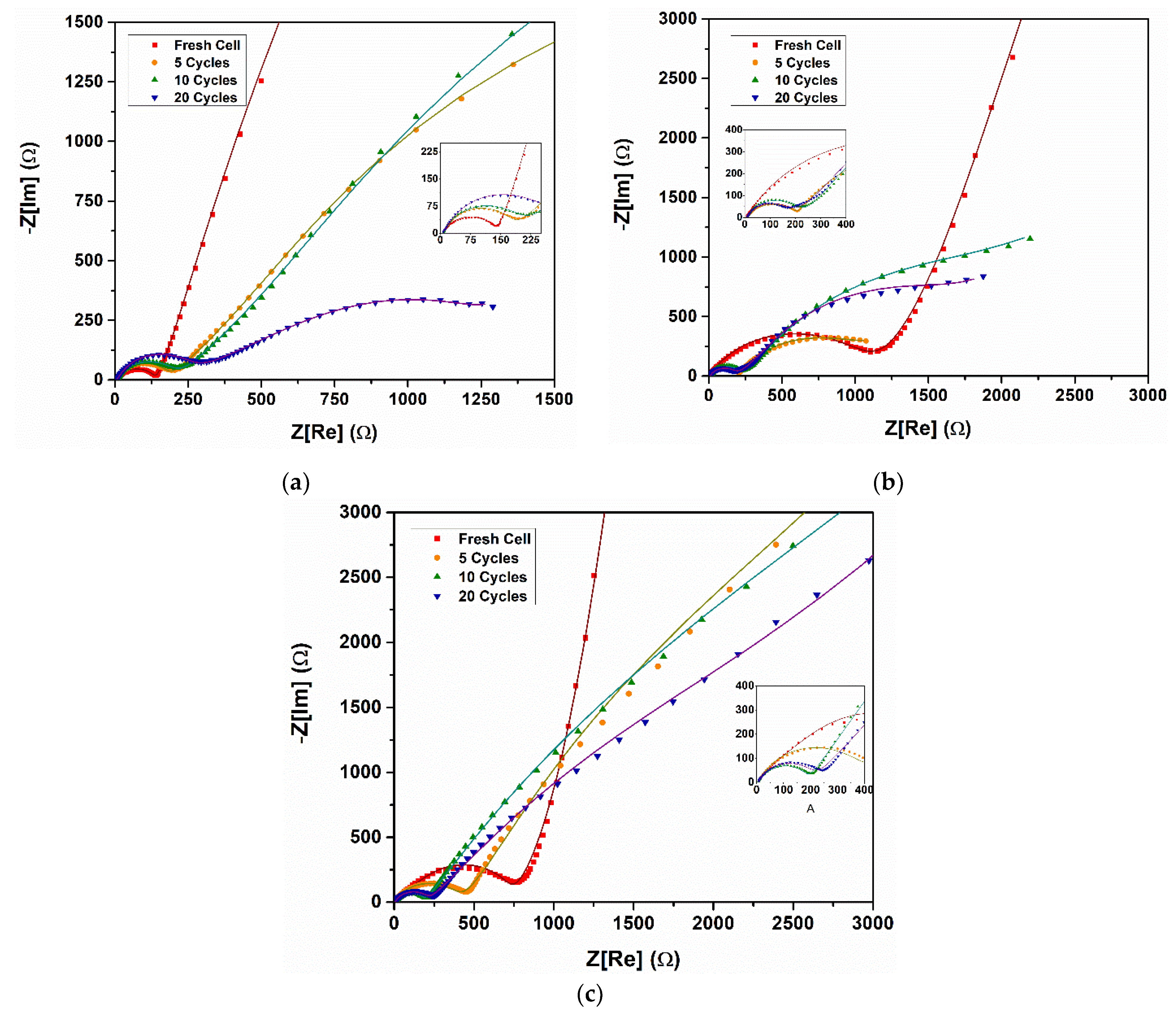
| Impedance Parameter | x\Cycle | 1st | 5th | 10th | 20th |
|---|---|---|---|---|---|
| Rsf (Ω) | 0.3 | 14,760 | 900 | 900 | 1067 |
| 0.5 | 505.4 | 81.03 | 65.37 | 2087 | |
| 0.7 | 435.1 | 2688 | 5000 | 1500 | |
| Rct (Ω) | 0.3 | 130 | 167.9 | 197.5 | 221.1 |
| 0.5 | 0.9519 | 1758 | 965.9 | 66.63 | |
| 0.7 | 265.7 | 400 | 180 | 200 | |
| Re (Ω) | 0.3 | 7.901 | 7.217 | 7.539 | 3.273 |
| 0.5 | 9.380 | 4.45 | 4.807 | 6.000 | |
| 0.7 | 4.408 | 7.501 | 1.532 | 5.699 |
Publisher’s Note: MDPI stays neutral with regard to jurisdictional claims in published maps and institutional affiliations. |
© 2022 by the authors. Licensee MDPI, Basel, Switzerland. This article is an open access article distributed under the terms and conditions of the Creative Commons Attribution (CC BY) license (https://creativecommons.org/licenses/by/4.0/).
Share and Cite
Nazario-Naveda, R.; Rojas-Flores, S.; Juárez-Cortijo, L.; Gallozzo-Cardenas, M.; Díaz, F.N.; Angelats-Silva, L.; Benites, S.M. Effect of x on the Electrochemical Performance of Two-Layered Cathode Materials xLi2MnO3–(1−x)LiNi0.5Mn0.5O2. Batteries 2022, 8, 63. https://doi.org/10.3390/batteries8070063
Nazario-Naveda R, Rojas-Flores S, Juárez-Cortijo L, Gallozzo-Cardenas M, Díaz FN, Angelats-Silva L, Benites SM. Effect of x on the Electrochemical Performance of Two-Layered Cathode Materials xLi2MnO3–(1−x)LiNi0.5Mn0.5O2. Batteries. 2022; 8(7):63. https://doi.org/10.3390/batteries8070063
Chicago/Turabian StyleNazario-Naveda, Renny, Segundo Rojas-Flores, Luisa Juárez-Cortijo, Moises Gallozzo-Cardenas, Félix N. Díaz, Luis Angelats-Silva, and Santiago M. Benites. 2022. "Effect of x on the Electrochemical Performance of Two-Layered Cathode Materials xLi2MnO3–(1−x)LiNi0.5Mn0.5O2" Batteries 8, no. 7: 63. https://doi.org/10.3390/batteries8070063