
Framework for BIM-Based Simulation of Construction Operations Implemented in a Game Engine
by
 , , , and
Carlos A. Osorio-Sandoval
1,* ,
,
Walid Tizani
1 ,
,
Estacio Pereira
2,
Jelena Ninić
1 and
Christian Koch
3 1
Department of Civil Engineering, The University of Nottingham, Nottingham NG7 2RD, UK
2
Department of Civil Engineering, The University of Calgary, Calgary, AB T2N 1N4, Canada
3
Faculty of Civil Engineering, Bauhaus-Universität Weimar, 99423 Weimar, Germany
*
Author to whom correspondence should be addressed.
Buildings 2022, 12(8), 1199; https://doi.org/10.3390/buildings12081199
Submission received: 11 July 2022
/
Revised: 27 July 2022
/
Accepted: 3 August 2022
/
Published: 10 August 2022
(This article belongs to the Special Issue Advances and Applications of Modeling and Simulation in Construction Operations)
Abstract
:Construction simulation has been widely used in academia for research purposes. However, it has been neglected by the industry for various reasons, including the amount of data, skills, effort, and time required to develop complex simulation models, the difficulty of model reuse, and the abstract and confusing way in which simulation results are usually presented. This article demonstrates how BIM can be employed to facilitate the development of a construction simulation model that considers constraints related to resource allocation and task interdependencies. Furthermore, it shows how a game engine can be used as a platform to implement the proposed framework for the integration of BIM and construction simulation and to produce animations from simulation results. The feasibility of the framework is demonstrated through a case study on masonry construction. Results of implementing the framework reveal that BIM-based simulations can reduce the skills, effort, and time required to develop simulation models and enable model reuse. The integration of simulation-based animations provides a model verification and validation mechanism and a means to communicate model results to stakeholders unfamiliar with simulation.
1. Introduction
Construction simulation is the method of modelling construction systems to understand their behaviour and digitally experimenting with the model [1]. In the context of this research, construction simulation refers specifically to modelling the construction process of an asset at the operational level. These models are used to represent the sequence of tasks or activities of a construction operation or project, their key performance indicators, such as duration and cost, and the utilisation of different resources, including materials, equipment, labour, and space during the execution of such tasks. Simulation has become the method of choice for comparative research as it provides means to test what-if scenarios in a timely manner [2]. Traditionally, the prevalent approach for simulating construction systems has been discrete-event simulation (DES) [3], which refers to modelling a system as it evolves by a representation in which state variables change instantaneously at separate points in time at which an event occurs [4]. DES systems have been successfully implemented at the operational and project levels independently in a wide range of applications in research [5], for example, estimating the impact of diverse variables on the duration of construction projects and operations [6,7,8,9,10], studying and improving safety performance of construction projects [11,12], supporting decision making and resource management [13,14,15], and studying and improving construction operations [16]. However, there are still barriers that prevent its widespread adoption by the industry, such as the amount of data, skills, effort, and time required to develop complex simulation models, the difficulty of model reuse, and the abstract and confusing way in which simulation results are usually presented [3,17,18,19].
On the other hand, building information modelling (BIM) is one of the most promising recent developments in the architecture, engineering, and construction industry. With BIM technology, an accurate virtual model of a building is digitally constructed [20]. This model contains precise geometry and relevant data, which is needed to support the design, procurement, fabrication, and construction activities required to realise the building [21]. BIM technologies have been quickly adopted by industry practitioners, as a wide variety of stakeholders are demanding BIM and changing contract terms to enable it [20].
In recent years, researchers have attempted to integrate BIM and construction simulation techniques in an effort to overcome the barriers to adopting simulation in the industry [22,23,24,25,26,27,28]. However, most attempts have relied on using BIM-generated quantity take-offs as input for the simulation models, which on its own is not sufficient for detailed construction simulations. Constraints related to resource allocation and task interdependencies should also be considered. Moreover, a methodology to achieve this integration while exploiting the benefits of both technologies in a simple, expandable, and customisable way is still needed. Among these benefits, 3D visualisation of simulation results should not be overlooked.
This article presents a framework that integrates BIM and construction simulation within a game engine. The simulation approach of the proposed framework leverages various modelling paradigms to account for their individual shortcomings, including distributed simulation, hierarchical control structures, and parametric modelling. The proposed framework generates a BIM-based construction simulation model that considers resource allocation and task interdependencies constraints. In the presented approach, generic simulation models of construction activities are associated to the BIM components that represent visually the products of such activities. Furthermore, the framework produces simulation-based animations, which can be used for model verification and validation. The modeller can look at such animations to compare the actual behaviour of the model to what was intended (verification). A domain expert can look at the animations to determine whether the behaviour of the model as intended by the modeller represents accurately the real-life system (validation). Equally, the animations can be used for other visualisation purposes, such as presenting alternatives to stakeholders and identifying safety hazards. The feasibility of the proposed framework is demonstrated through a case study on masonry construction.
The primary aim of this research is to investigate how to use a BIM model to facilitate the development of a construction simulation model that takes into account constraints related to resource allocation and task interdependencies. This was accomplished by linking a BIM model and generic simulation models within a game engine, leveraging the functionality of the latter. This enabled a user-friendly manner to develop BIM-based simulation models with a straightforward data exchange between the BIM model and the simulation model. Moreover, the game engine provided an environment to enhance the visualisation of simulation results through animations.
2. Background
Even though construction simulation has been proven to be a valuable tool for planning and decision-making support, it has been neglected by the industry for many reasons. A few comprehensive studies aiming at identifying the key challenges and barriers that have hindered the adoption of simulation techniques in practice have been carried out in the past decade [17,18,19]. The most frequent barriers reported in the literature are related to the limitations of the construction simulation tools and methods, which are often unable to represent the reality of construction systems [19] or enable model reuse. Moreover, the typical modelling approaches adopted in construction simulation, which are often borrowed from other industries, such as manufacturing, lack the generality to easily capture the modelling needs or complex decision-making mechanisms of construction [29], such as resource allocation and task interdependencies constraints.
There is an essential need to streamline the model development process while enabling model reuse and enhancing the way in which the results are communicated to stakeholders that are unfamiliar with simulation. This research presents a framework that semi-automatically generates a BIM-based construction simulation model. The framework produces animations to communicate simulation results by leveraging BIM and game engines. The framework enables model reuse and has the potential to reduce the skills, effort, and time required to develop construction simulation models. In the remainder of this section, we briefly discuss related work.
2.1. BIM-Based Simulation
Developing and maintaining construction simulation models takes a significant amount of time and effort and requires specialised skills [19,23]. Furthermore, preparing the required input data to produce accurate simulation results is also time-consuming and error-prone [22,24,30,31].
In an effort to overcome these issues, researchers have attempted to integrate BIM with construction simulation, leveraging BIM models in different ways: (1) using BIM-generated quantity take-offs to calculate the duration of construction operation models [22,23,24,28] and for entity creation [2]; (2) extracting and enriching information from BIM to guide entities through simulation models [25] and to use as simulation resource data [26,32]; (3) using BIM databases as input for simulation models [27]; (4) assigning simulation models of construction activities to individual building components of a product model to interactively define complex simulation models [2,22,30]. This approach offers the additional benefit of enabling the reuse of simulation models across different projects, which is generally not possible in the context of simulation [1].
2.2. Simulation Model Reuse
Simulation model reuse is believed to reduce the amount of time and effort required to build new models [33] while leading to higher quality simulation studies [34]. Model reuse ranges from using small portions of code to full model reuse. In this article, two modelling paradigms are combined with BIM to enable simulation model reuse at a component level: a distributed simulation and parametric modelling.
Distributed simulation allows existing models to be composed together to form simulations of large-scale systems [35]. In this approach, independently developed submodels can be reused to develop an integrated model in a “grab and glue” fashion. Typically, distributed simulations consist of several simulation models that communicate through a computer network [36]. A different way to distribute a simulation, adopted in this research, is to decompose the model into several submodels [4] that do specific functions while communicating between them.
Parametric modelling is a geometric modelling process with the ability to change the shape of a model as soon as a dimension variable value is modified [37]. In this approach, new instances of an object can be created by assigning new values to a set of predefined parameters [38] and modified without the need to redraw the model whenever it needs a change [37]. Both industry and academia have dedicated efforts to improving parametric modelling technology, as evidenced by the prevalence of BIM, for which 3D parametric modelling is central [38]. However, in the construction simulation domain, this paradigm has not been fully exploited. A parametric simulation model could be scaled by parameters that represent some of the project-specific constraints that are prevalent in construction. Such parameters could modify directly one or more process models or the control units that determine their behaviour. For example, based on the height of a wall, it may be determined that a scaffolding system is required, thus prompting the model to direct entity flow to a scaffolding installation submodel. An existing commercial cloud-based tool that can simulate parametric construction projects and show 3D visualisations of the simulation results [39] has recently entered the UK market [40].
2.3. Enhancement of Simulation Visualisation through Animation
Simulation results are often abstract and confusing [27], leading decision makers to misinterpret or fail to apply them. Simulation is often delegated to specialists and decision makers who separate themselves from the process [41], which leads to a lack of trust by industry practitioners toward their effectiveness [18]. The field of simulation in construction is moving toward its integration with other tools, with a special interest in enhancing visualisation [3]. An example of this is the visualisation of site layout plans created within simulation environments, which enables planners to experiment with different site layout plan alternatives with minimal effort [42]. Simulation-based animation is viewed as an appropriate tool to reduce the complexity in which simulation results are presented to stakeholders unfamiliar with simulation. In an animation, the operational behaviour of a simulation model is displayed graphically as the model moves through time [43]. Researchers in the field use post-processing visualisation [44], in which “trace files” generated during the simulation are used to produce an animation that replicates what happened after the simulation finishes [45]. Compared to traditional 4D modelling, this type of animation has the potential to delve into the details of resource interactions and site-level changes, because the locations and status of the resources are known during the simulation.
Although there are many documented research attempts to improve the visualisation of simulation results through animations [41,44,45,46,47,48,49], few have leveraged BIM data and game engines to accomplish this. The gaming industry is one of the leaders in utilising and advancing visualisation technologies [44]. Gaming technologies, especially game engines, have drawn the attention of researchers in the construction simulation field. Game engines provide ways to achieve immersion in visualisation due to their compatibility with mixed reality technologies, ubiquity as they offer multi-platform deployment, high-quality graphics, and network capabilities that allow for multiple simultaneous users, among other characteristics [50].
3. Methodology
This research adopted a design-science methodology [51] to create an artefact that facilitates the development of construction simulation models using BIM. This article presents a conceptual framework that represents the proposed artefact. The conceptual framework was implemented in a game engine-based artefact and demonstrated through a case study on a typical construction management problem.
3.1. Framework Design
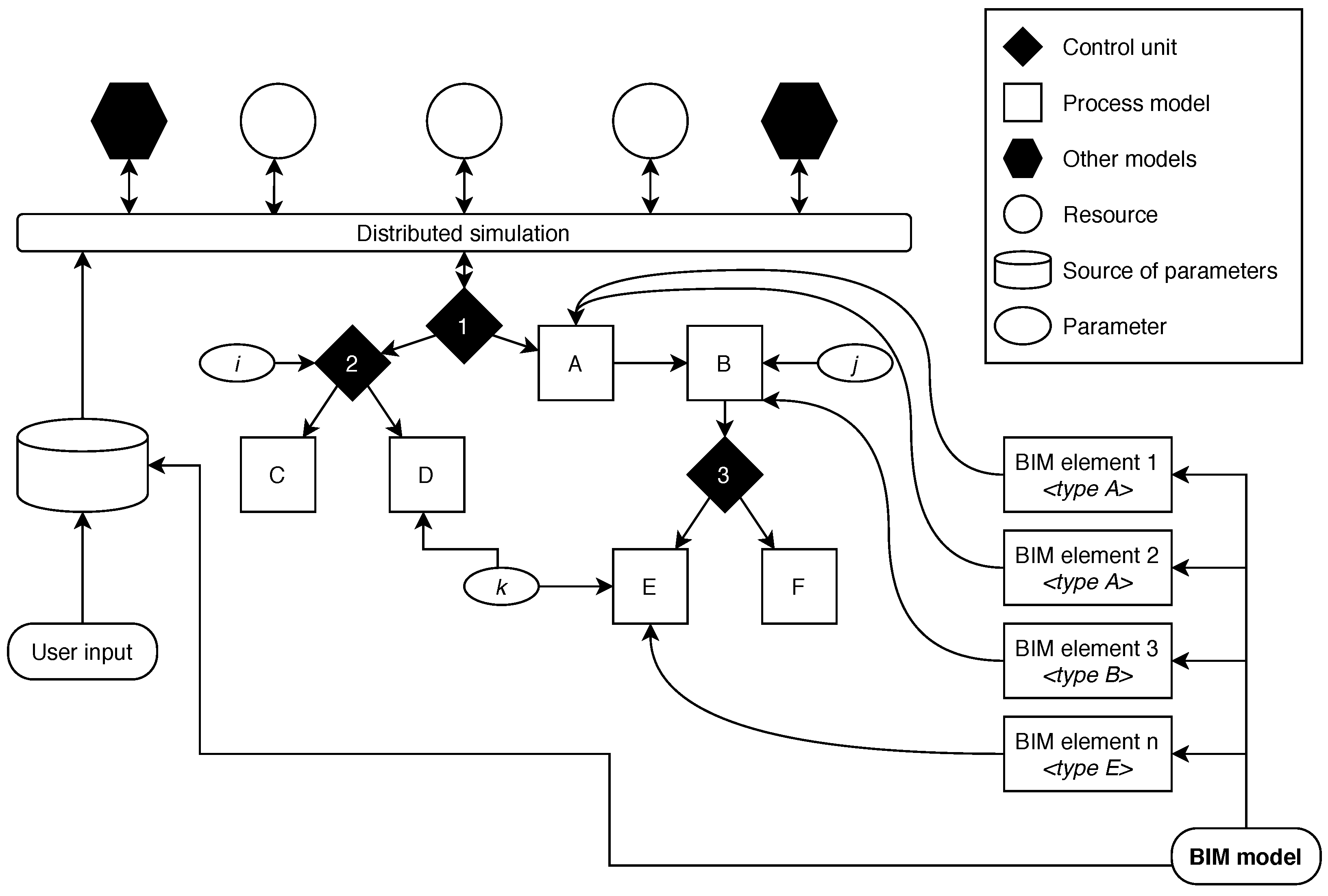
The five modules of the proposed framework were designed based on the following requirements: (1) Reuse of simulation models; (2) Simulation modelling flexibility; (3) Decision-making mechanism; and (4) BIM-based. The simulation approach that underpins the proposed framework (shown as an example in Figure 1) is based on the distributed simulation paradigm. Submodels representing different construction activities (white squares in the figure) are composed together through hierarchical control units [52] (black rhombuses in the figure) with parameter-based rules (white ovals in the figure) that determine the conditional behaviour of the model. Resources (white circles in the figure) and factors that affect construction, such as equipment breakdown, weather, procurement delays, and absenteeism (black hexagons in the figure) can be modelled independently. The control unit of each construction activity submodel subscribes to the parameters published by these other models. Implementing a hierarchical control structure to control entity flow in a distributed simulation provides a mechanism to allocate shared resources among tasks of different construction activities and to comply with project-specific decision-making rules. Moreover, the federated simulation model can be scaled by parameters that represent project-specific constraints prevalent in construction. Such parameters modify directly one or more submodels or the control units that determine their behaviour. These modifying parameters may be related to the product of the construction (product parameters) or the constraints of the project (project parameters).
In the adopted simulation approach, parametric simulation models of construction activities are assigned to individual BIM elements based on their type, as shown in Figure 1. These parametric models are generic in nature, because they can represent the construction process of a variety of construction products of the same type based on product and project-specific constraints. New instances of the construction activity submodels are created based on the product parameters provided by the BIM elements. These new submodels are specific rather than generic, as they represent the construction activities required to build the BIM elements that provided the parameters to instantiate them. Each of the submodels contains a control unit that determines its behaviour based on rules that depend on the product parameters provided by the BIM element.
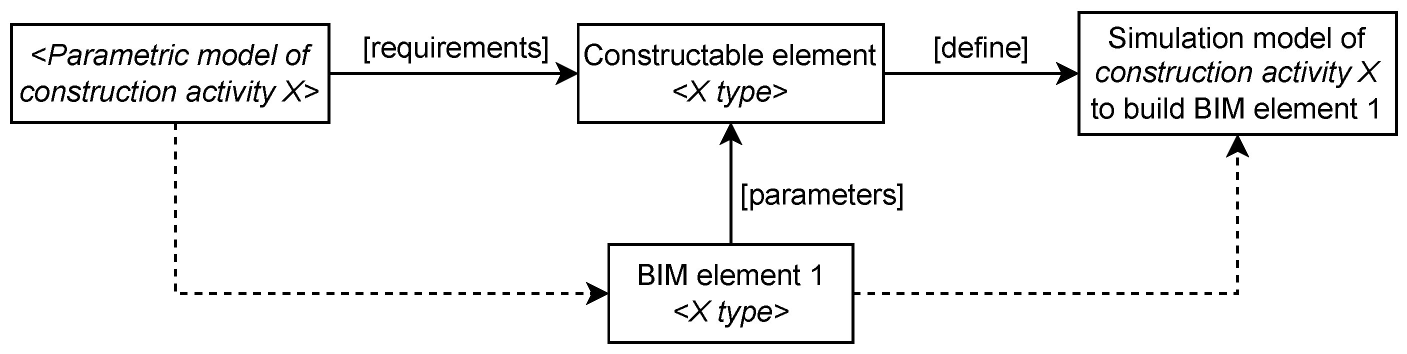
The advantage of using a BIM model to provide the product parameters to the simulation models is that a lot of the required object definitions are already provided in BIM. However, temporary elements, which are frequently essential to consider in a simulation model, such as formwork, are not generally defined in the BIM model [24]. Although the locations of BIM elements are defined in the model, the spatial relationships between them and site-related locations (i.e., locations of material storage sites, work stations) are not defined in the BIM model either. To overcome these limitations, an interface (called Constructable Element) that translates BIM data into the simulation models requirements has been developed for the proposed framework. Figure 2 depicts the relationship between a BIM element, its corresponding Constructable Element interface, and its generic and specific simulation models.
The framework was implemented in a game engine. Game engines provide the complex technological foundation upon which digital games are built [53]. They are commonly implemented as an integrated collection of modules with different functionalities, for example, graphics generation, physical behaviour of objects, collision detection, user interaction, sound management, etc. [54]. Four game engine related concepts were leveraged to achieve the sought functionality of the proposed framework, namely, game objects, game components, scripts, and reusable assets. Section 5 details how these concepts were used.
3.2. Simulation-Based Animations
In the proposed framework, a game engine is used to visualise an animation of the simulation results. The approach used to generate the simulation-based animation is to adopt post-processing visualisation. A collection of chronologically ordered trace files indicating the position and state of materials, workers, and equipment during each step of the simulation is generated for each simulation run following an object-oriented approach. When a simulation event occurs, the attributes of the game objects that represent the different resources involved in the event are modified and a new trace file is published. The new trace file saves the attributes of the relevant game objects at the corresponding simulation time. During the animation, the trace files are “played back”. The resulting animation shows the interaction between the different resources involved in the construction process of the element. The animations can be visualised in a 3D environment that domain experts unfamiliar with simulation can easily interpret.
Besides supporting the visualisation of simulation results, simulation-based animations have the following contributions to the proposed framework: (1) Model verification and validation. Verification is defined as ensuring that the model matches the modeller’s understanding of the system [55]. Validation confirms if the model possesses a satisfactory range of accuracy consistent with its intended application [43]. Simulation-based animations can serve both purposes [43] as modellers can view the animation to check the behaviour of the simulation model against its conceptual design to verify that it reflects their intentions and domain experts can use the animation to validate the model. (2) Planning support. Simulation models are designed to help decision makers make decisions or gain a better understanding of the modelled system [33]. Visualisation assists in investigating events that are hard to quantify in a definitive manner but yet can affect the final outcome, for example, work zones overcrowding or safety hazards [56]. Although 4D modelling is widely used for visualisation of construction, it only allows for the visualisation of construction schedules, remaining on the level of visualisation and not planning [32].
4. Proposed Framework
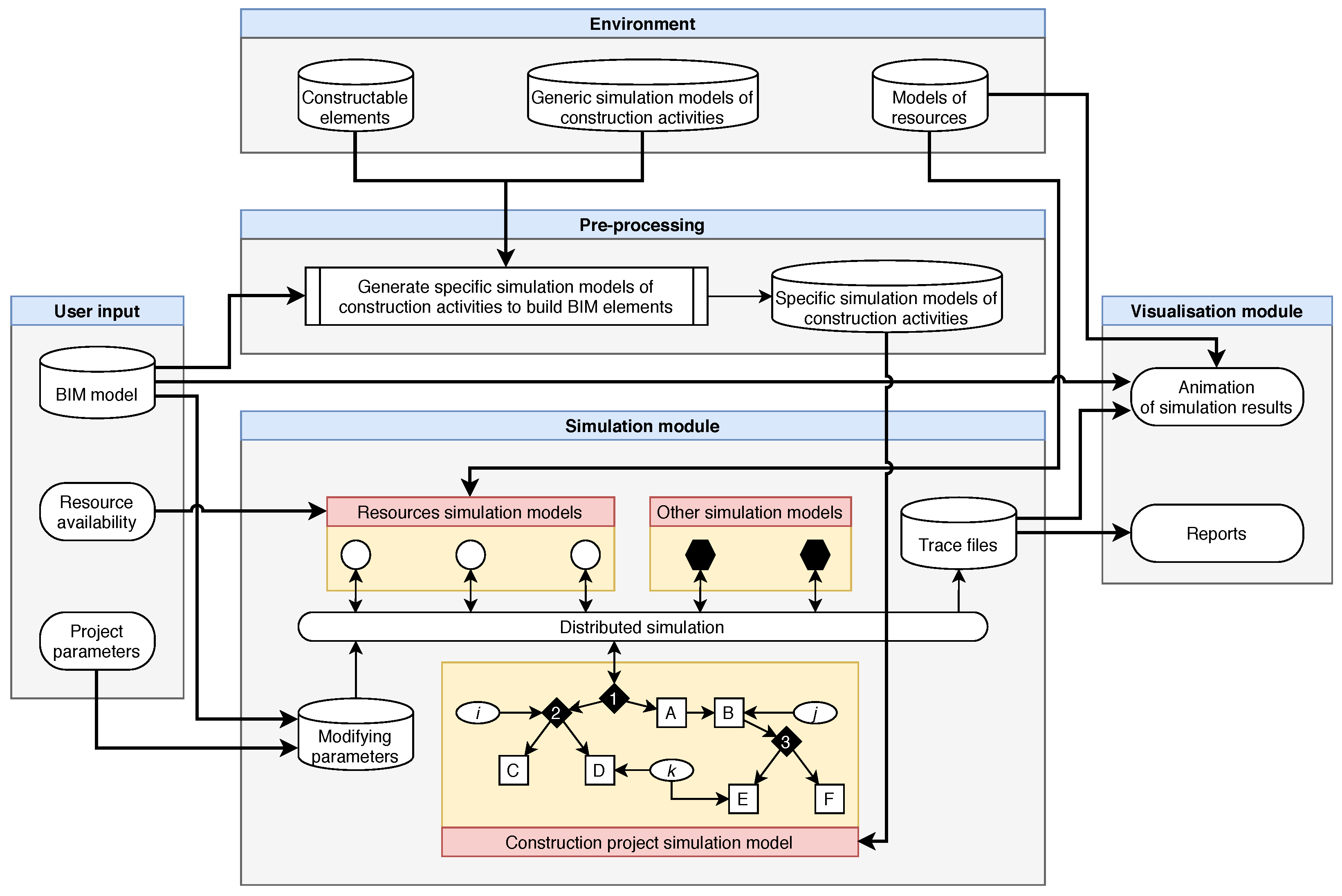
This article proposes a framework to integrate construction simulation and building information modelling. The framework, depicted in Figure 3, is composed of five main modules: (1) The environment module, preloaded with a library of generic simulation models of different construction activities; (2) The user input, which includes the facility to import existing BIM models; (3) The pre-processing module, which generates a BIM-based simulation model; (4) The simulation module, in which users can experiment with the model; and (5) The visualisation module, which produces reports and simulation-based animations to support planning and decision making.
The proposed framework links an existing BIM model to generic simulation submodels of construction activities within a game engine. Such submodels are implemented as script game components within the engine. This approach provides a means to develop a BIM-based construction simulation model in a quicker manner compared to traditional simulation modelling. The framework also enables a straightforward way to exchange data between BIM elements and their corresponding simulation models, which allows easy scenario exploration. The game engine also enhances the visualisation of the simulation results through 3D animations.
4.1. Environment Module
The environment module consists of three components: Constructable Elements, generic simulation models of construction activities, and resource models. These components enable the semi-automatic generation of a BIM-based construction simulation model and subsequent production of simulation-based animations. Each component of the environment module can be seen as a container that stores loadable elements that the system uses to develop simulation models and animations. Once stored in their corresponding container, these elements can be reused as-is across multiple projects that involve similar construction products or resources. Each container can be expanded with new elements developed from scratch or adapted from existing elements to accommodate the user’s requirements.
The Constructable Element is an interface that extracts data from BIM elements and translates them into the requirements of the simulation models of construction activities. It enriches the extracted data to include required parameters that are not in the original BIM model but that can be computed from its product parameters (e.g., formwork areas). The Constructable Element interface supports the Industry Foundation Classes (IFC) format. It can also generate the required parameters based on the geometry of a 3D model in different formats (e.g., fbx). This feature enables interoperability with non-IFC-based 3D modelling tools and flexibility in the 3D modelling approach of designers. The extracted and enriched data that the Constructable Element transfers to the generic simulation models of construction activities serve four purposes: (1) Assign a generic submodel from the library to the BIM element; (2) Compute the amount of materials required to complete the construction process of the element; (3) Assign values to parameter-based rules in the control units of the submodels; and (4) Establish interdependencies with other submodels based on the topological relationships of their BIM elements.
The generic simulation models of construction activities consist of parametric simulation submodels that represent the construction process of products of the same type. These submodels consist of two components: (1) A control unit that determines the flow of the system through a predefined parameter-based decision mechanism; and (2) One or more tasks that specify which resources change, how they change, and the time span (task duration) over which the changes occur when the task takes place in the simulation. Task durations can be either deterministic or stochastic. New instances of the submodels are generated based on the parameters of each BIM element in the project. Their control units are automatically linked to control units in higher levels of the control structure hierarchy upon instantiation. Communication between control units at different levels of the hierarchy is both ways, meaning that the submodel of one activity can communicate with another submodel through the control unit at the level above them. This feature allows for the consideration of the interdependencies between tasks of different submodels without re-formalising them.
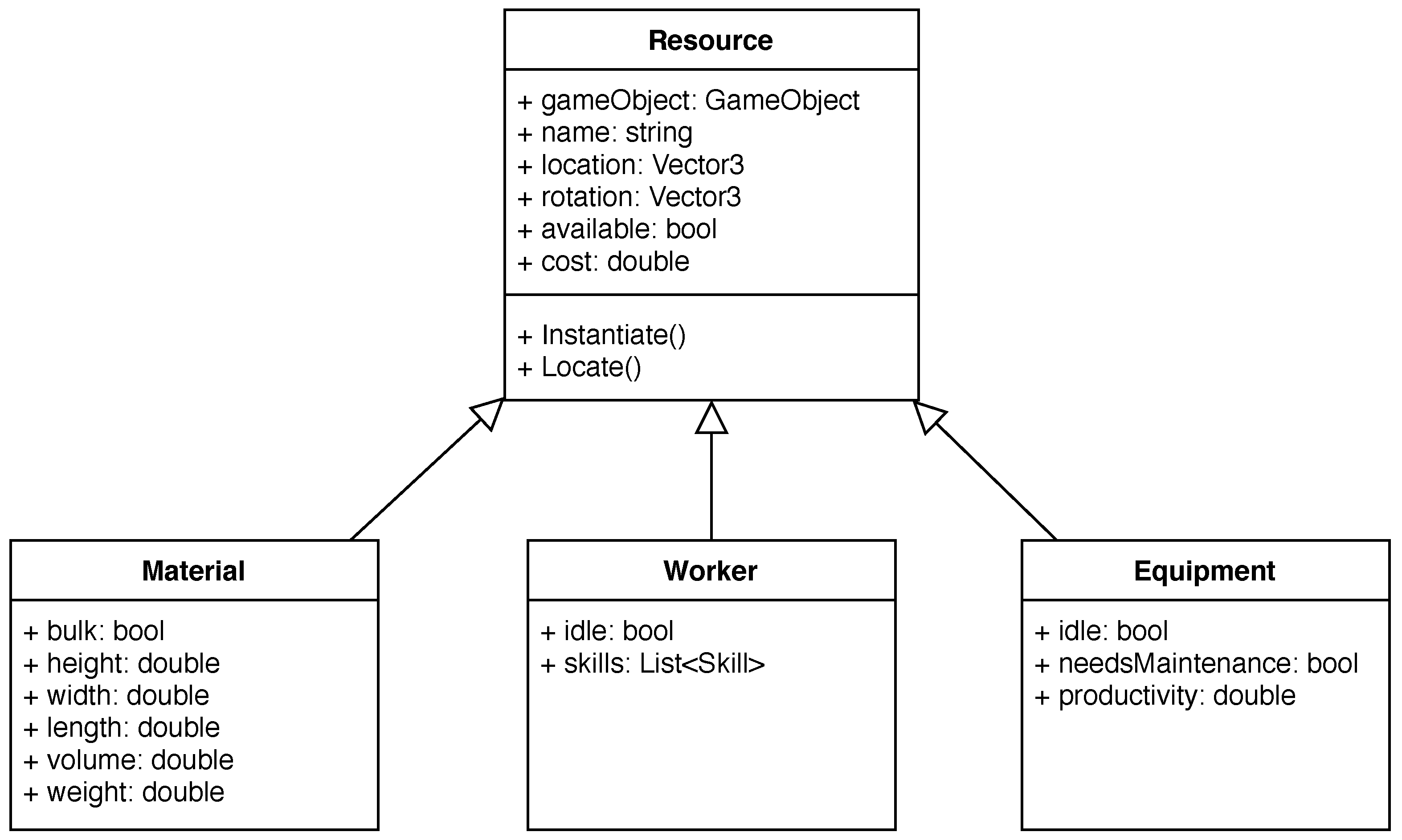
Resources in the framework are modelled following an object-oriented approach. Each resource object in the environment consists of the combination of a 3D model that represents the resource in the animation and a set of attributes that represents it in the simulation. In a construction activity, resources can be classified into material, worker, or equipment types. Although all resource types share some attributes, each type has some unique ones, as illustrated in Figure 4. These attributes can be extended as required by the model. Materials can be classified as discrete or non-bulk materials, such as bricks or reinforcement bars, and bulk or non-discrete materials, such as water or cement. Materials in the environment module of the proposed framework can represent both types. Workers have two unique attributes, their state during simulation, which can be either idle or busy, and the list of skills that they have, which makes them eligible to perform different tasks during the simulation. Each instance of the equipment type should represent a specific type of equipment that the simulation model demands. The adopted simulation approach allows modelling equipment breakage and maintenance as independent submodels that constrain equipment availability in the integrated model based on rules imposed by the modeller.
4.2. User Input Module
This module is composed of three components: (1) A BIM model, composed of BIM elements from which the Constructable Element interface extracts the relevant information to develop the simulation model. This includes the element type, a unique identifier, the coordinates that place the element in a specific location in reference to a known base point, and the element’s geometry. (2) Resource availability and constraints, including the number of available workers and the skills that each worker has, the number and type of available pieces of equipment, and the location, capacity, and restock frequency of material storage sites. (3) Project-specific parameters, such as working shifts, limits on the number of workers on the site at the same time, explicit interdependencies between submodels determined by the preferred construction strategy, etc.
In addition, users can input independent models to represent other project-specific constraints. Examples of these factors are labour absenteeism, equipment breakage and maintenance, material procurement processes, safety inspections, or location-based weather.
4.3. Pre-Processing Module
This module facilitates the development of the simulation model of a construction project based on its BIM model. It instantiates specific submodels of the construction activities required to build each element in the BIM model by assigning values to the parameters of the corresponding generic submodels. Such values are extracted from the BIM elements by an instance of the Constructable Element interface. Figure 5 depicts the flow diagram of the this module of the proposed framework.
4.4. Simulation Module
This module is composed of five components: (1) A distributed simulation component; (2) A construction project simulation model; (3) Resource simulation models; (4) Other simulation models; and (5) Trace files. The first four components make up the conditions under which the simulation is carried out, whereas the latter one produces the results for visualisation and analysis.
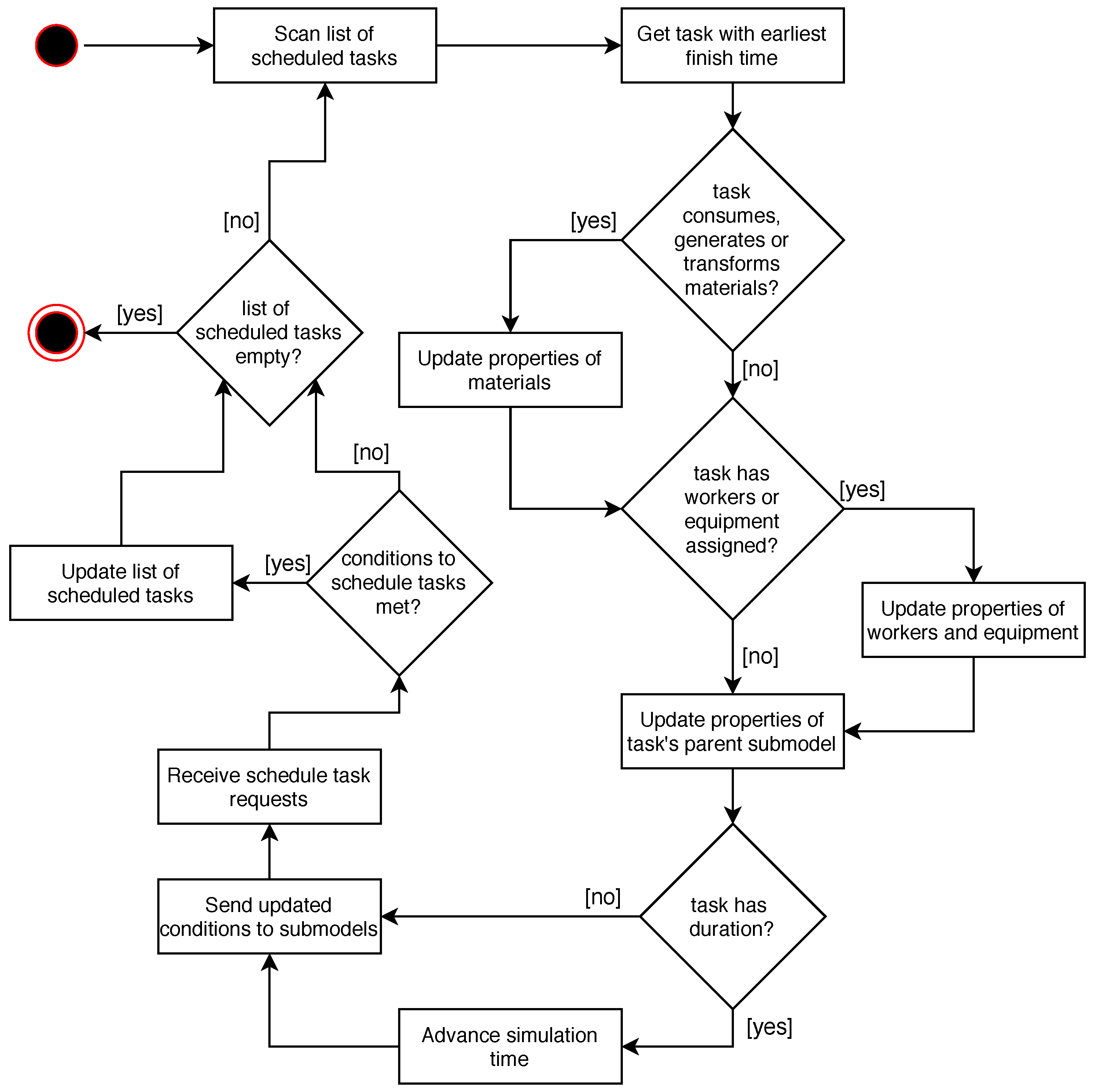
The distributed simulation component is the central component of the module. It interacts with all the other components and it contains the required infrastructure to run the simulation, including resource allocation to tasks and simulation clock advancement. This component contains the control unit at the highest level of the control structure hierarchy of the simulation model, which obtains updates from other components regarding the current state of the project and resource availability. Subsequently, it sends signals downstream to the control units in lower levels of the hierarchy based on its predefined behavioural rules until all the conditions to execute one of the tasks of one of the submodels are met. The remaining components of the module can only communicate with each other through the distributed simulation component. Figure 6 depicts how the distributed simulation component of the simulation module advances the simulation clock and updates the properties of the submodels based on the scheduled task with the earliest finish time. The simulation clock is advanced to the finish time of the scheduled task that has been executed. A task is only scheduled when its precedent tasks are complete, and its required resources are available, at which point they are assigned to it.
The construction project simulation model component is composed of the specific BIM-based simulation submodels of construction activities generated in the pre-processing module. The control units of each of these submodels are linked to the control unit of the distributed simulation component.
During simulation time, several instances of the different resources involved in the construction project are available to participate in the tasks of the construction simulation model. The properties of each resource instance are available for reading and updating by the distributed simulation component based on requests generated by the tasks that utilise the resources.
Other simulation models can run concurrently with the construction simulation model. These models communicate with the distributed simulation component in a similar fashion to the construction simulation model. They can also send requests to acquire available resources, schedule tasks, advance the simulation clock, or interrupt scheduled tasks. With these approaches, factors such as labour absenteeism, equipment breakage and maintenance, material procurement processes, safety inspections, or location-based weather can be modelled independently. This approach enables modellers to reduce uncertainty by incorporating the behaviour of the factors that produce it into the model. Specific rules to respond to these factors can be included in the control units of the submodels of construction activities.
The trace files in the simulation module stores the information required to visualise and analyse the simulation results. During each simulation run, the distributed simulation component publishes a new time-stamped trace file every time that there is an update on the system. Essentially, the chronologically ordered set of trace files of a given simulation run is a detailed log of all the events that occurred during the simulation. Such sets of trace files include all the required information to produce reports on resource utilisation and task durations, as well as simulation-based animations.
4.5. Visualisation Module
The visualisation module of the proposed framework displays the simulation outputs in different ways, classified into two main categories: reports and animations.
Although a set of trace files generated in the simulation module contains a large amount of useful information for construction managers, these raw data need to be organised in order to support informed decision making properly. This is especially true when the durations of the tasks are not deterministic because more than one simulation run is necessary to obtain reliable results to make predictions on the performance of the project. In this case, more than one set of trace files becomes available to analyse, resulting in an immense amount of data. These data are used to produce four different types of reports: (1) Project duration reports, which show a frequency histogram of the resulting project duration in each simulation run, and the parameters of the normal distribution that adjusts to the project duration data set; (2) Schedules that are automatically generated for each simulation run at the activity level; (3) Productivity reports, which display productivity values computed at three levels: project, activity, and task; (4) Type-based resource histograms.
The visualisation module of the proposed framework produces a simulation-based animation for each simulation run. Such animations take as input three elements: (1) The 3D model subcomponent of the modelled resources; (2) The geometry of the BIM elements of the user input BIM model input; and (3) The set of trace files corresponding to the simulation run of interest. These animations can be replayed and visualised from multiple viewpoints. They show resource interaction in detail as the construction process progresses. Furthermore, leveraging the functionalities of the game engine, the animations can also be visualised in an immersive virtual reality environment, which has shown a great potential to improve workflow efficiency in the construction context through enhanced common understanding [57].
5. Implementation
The proposed framework was implemented as an application developed within the Unity game engine. The following game-engine-related concepts [58] were leveraged to achieve the sought functionality: Game objects are the fundamental objects that represent characters, props, and scenery. Game components implement the functionality of game objects. Scripts are a type of game component that consists of a piece of code that implements the developer’s own features. Scripts in this application were developed in C#, supported by Unity. Reusable assets are templates of game objects and their game components from which new instances of the game object can be created.
The Constructable Elements and the generic simulation models were implemented as script game components. For the latter, the SharpSim library, a C# open-source discrete-event simulation code library, was used. Models developed with SharpSim are composed of events and edges. Events cause a state change in the modelled system, and edges establish the relationships between the events and the flow of the system [59]. Although SharpSim allows the duration of tasks to be modelled stochastically, its built-in library of probability distributions is limited. Therefore, the Math.Net Numerics library [60], which provides methods and algorithms for numerical computations in C#, was used to model the duration of tasks.
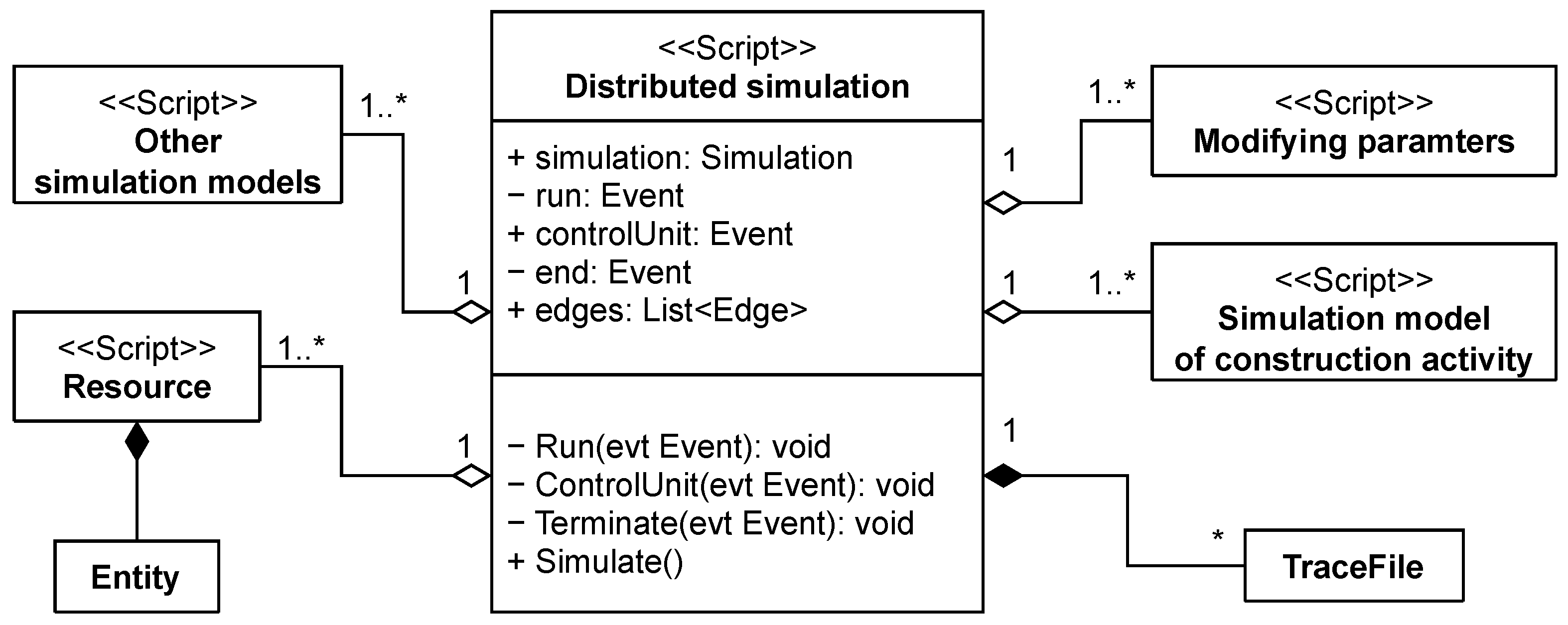
The distributed simulation component of the simulation module was implemented as a script game component developed in C#. Figure 7 depicts the class diagram of the distributed simulation component of this module and its relationships with other components. As the figure shows, the distributed simulation component is composed of three SharpSim events. First, the run event, which determines the beginning of the simulation. Second, a control unit event, which is the highest control unit in the control structure of the project. Third, an end event, which determines the ending of the simulation. Each SharpSim event requires a state change listener method, which takes the event as a parameter. In addition, this class has an object of the SharpSim Simulation type and a Simulate method that instantiates and executes all the simulation scripts associated to the distributed simulation component.
Resources were implemented as a 3D model and a script with a set of attributes attached to the same game object. The resulting game object composes a reusable asset. This approach allows the implementation of rules to prevent objects overlapping leading to insufficient work areas. This can be achieved by querying the scene to check if the number of objects of a certain type in a determined area exceeds a limit previously defined by the user. The location property of resources changes during simulation, and the changes are logged in the trace files.
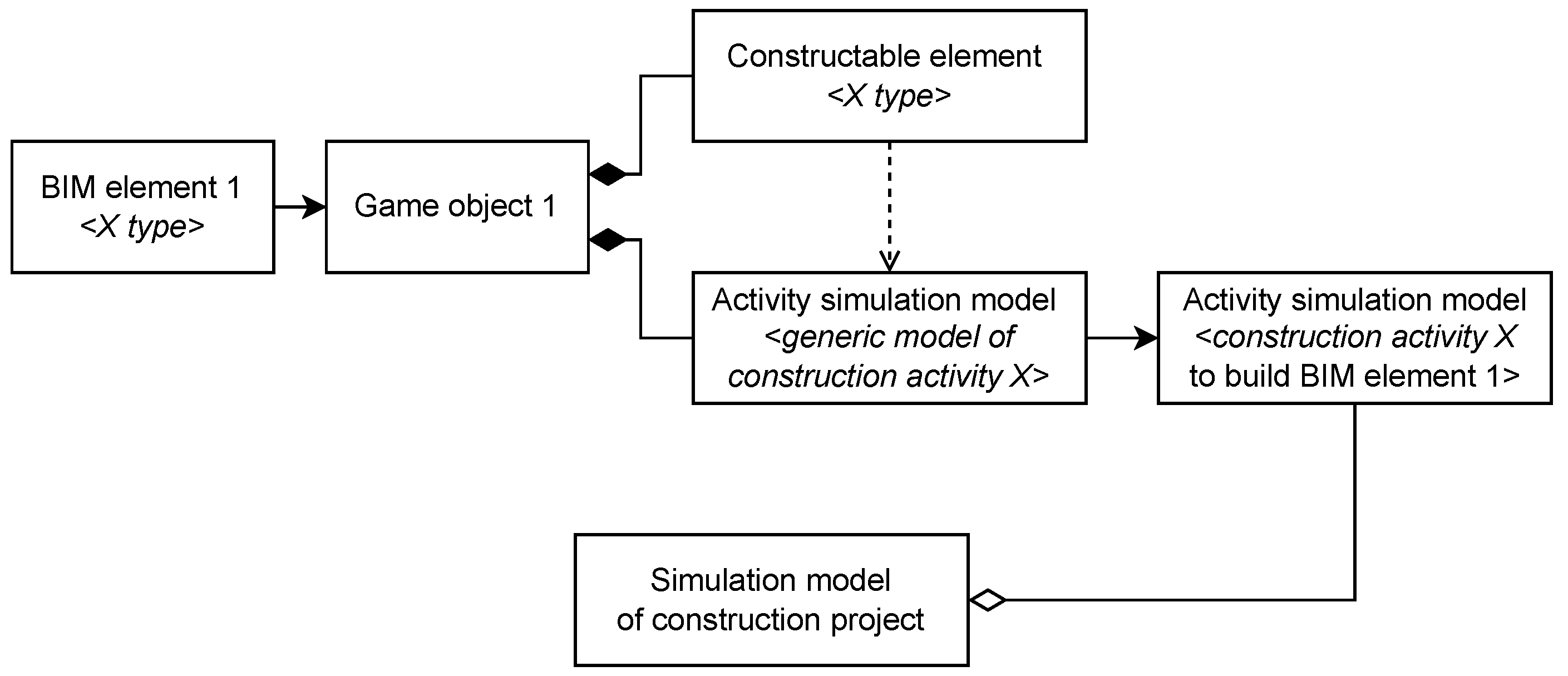
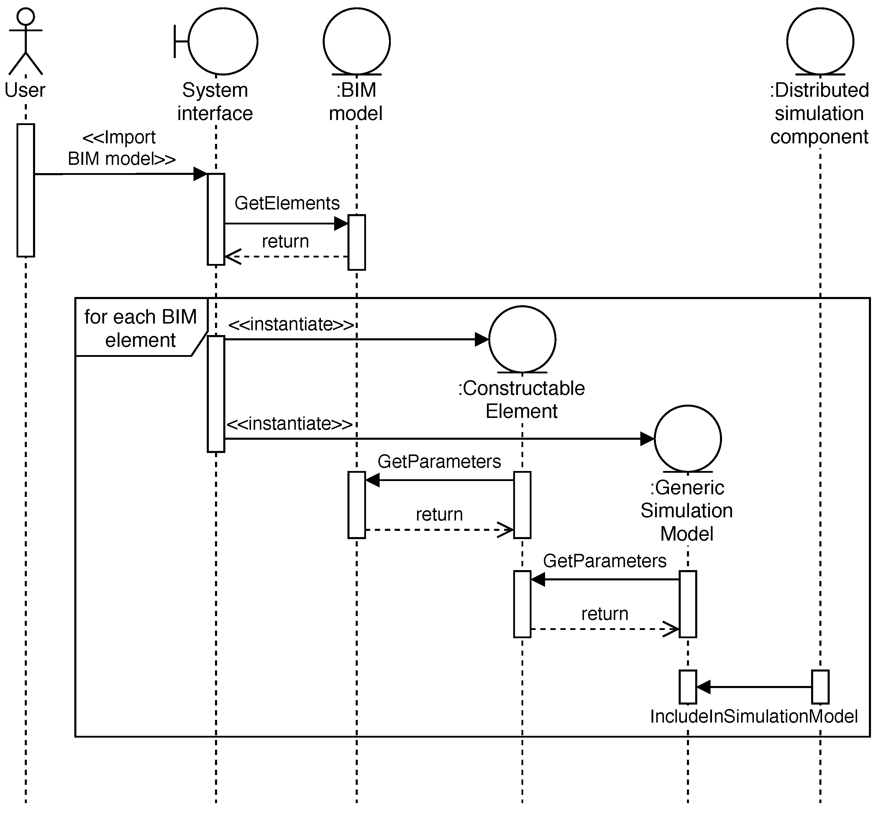
BIM models can be imported into the scene as an fbx file or as an IFC data model. Once imported, each BIM element of the model becomes a game object. Scripts of the Constructable Element and generic simulation model classes are instantiated and attached to BIM element game objects in the scene based on their type. A script is used to identify the BIM elements in the scene, assign the relevant instantiated scripts, execute a method to extract and enrich the BIM data, and feed the data into the generic simulation models. Next, the simulation models in the scene are no longer generic, because they represent the construction activities required to build the BIM elements associated with them, as illustrated in Figure 8. Subsequently, the distributed simulation component, also implemented as a script, can include the construction activity submodels to the federated simulation model, as depicted in Figure 9.
Trace files were implemented as scripts following an object-oriented approach. A new object of the trace file class containing all the relevant information to produce reports and animations is instantiated when there is a change in the modelled system.
6. Case Study
The application of the proposed framework and its components is demonstrated by implementing it in a case study on masonry construction for a housing project. A typical masonry crew consists of two types of workers, skilled workers (masons) and unskilled labourers (helpers). Depending on the job, the size and composition of this crew may vary. This case study analyses several compositions of crews performing the construction of masonry walls with concrete blocks in a large housing project to illustrate the employment of the proposed framework. Although the simulation model in this case study focuses on project duration, the same approach can be used to study other key performance indicators, such as cost, by adding the relevant criteria to the simulation model.
6.1. Project Description
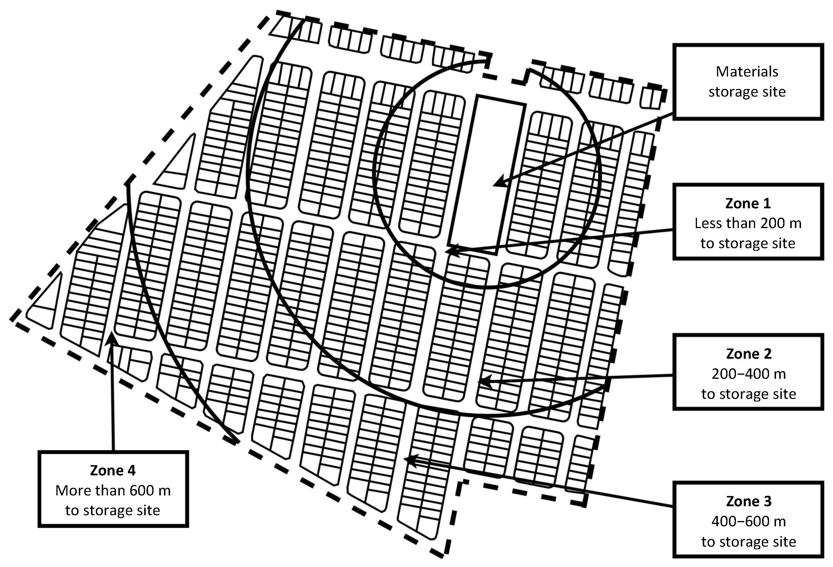
The selected project consists of the construction of 746 one-storey houses as part of a larger housing project in South East Mexico. The case study seeks to determine the number of helpers that a mason needs to keep a continuous workflow based on the distance between the house that the crew is working on and the material storage site. For this purpose, the site has been divided into four zones, as depicted in Figure 10.
6.2. Generic Simulation Model
The federated simulation model of the project is composed of an instance of a generic submodel of the selected construction activity for each masonry wall of the house prototype. This submodel consists of a C# script game component.
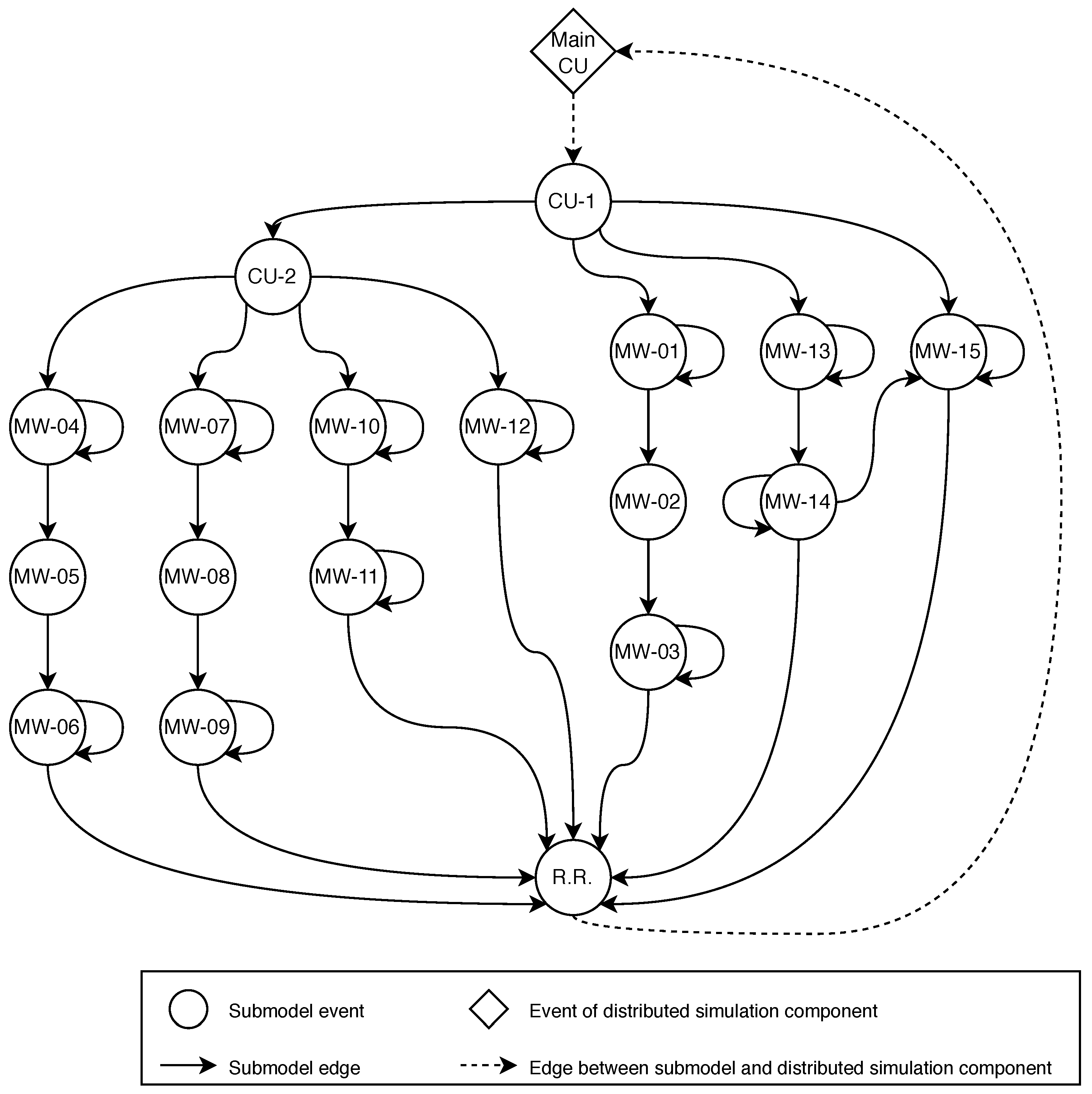
The selected construction activity was broken down into simpler tasks considering resource allocation factors, shown in Table 1. Figure 11 shows the conceptual model of the activity, where circles represent submodel events, diamonds represent events of the distributed simulation component, continuous arrows represent edges that link events within the submodel, and dashed arrows represent edges that link events in the submodel with events in the distributed simulation component. The activity submodel is composed of eighteen events, representing the tasks documented in Table 1, the submodel’s control units (CU-1 and CU-2), and an event that updates the distributed simulation component when resources are released (R.R.). Table 2 and Table 3 show the control mechanism of CU-1 and CU-2. Table 4 shows the probability distributions of the durations of the submodel tasks.
6.3. Constructable Element
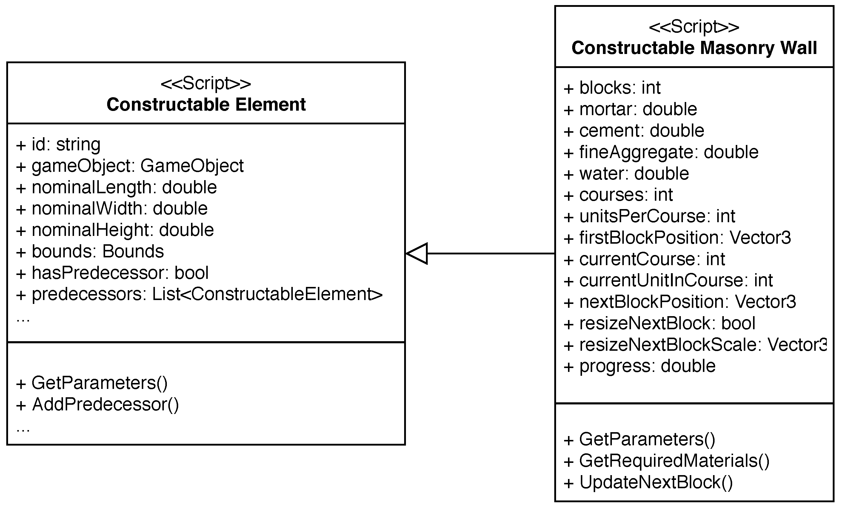
Figure 12 depicts the class diagram of the Constructable Masonry Wall. A script based on this class was developed to extract geometric data from the masonry walls of the BIM model of the house and translate it into the requirements of the activity submodel. Such information determines the amount of materials required to complete each submodel, the final position, rotation and scale of the concrete blocks within the 3D environment, and the construction progress of the activity during the simulation.
6.4. BIM Model
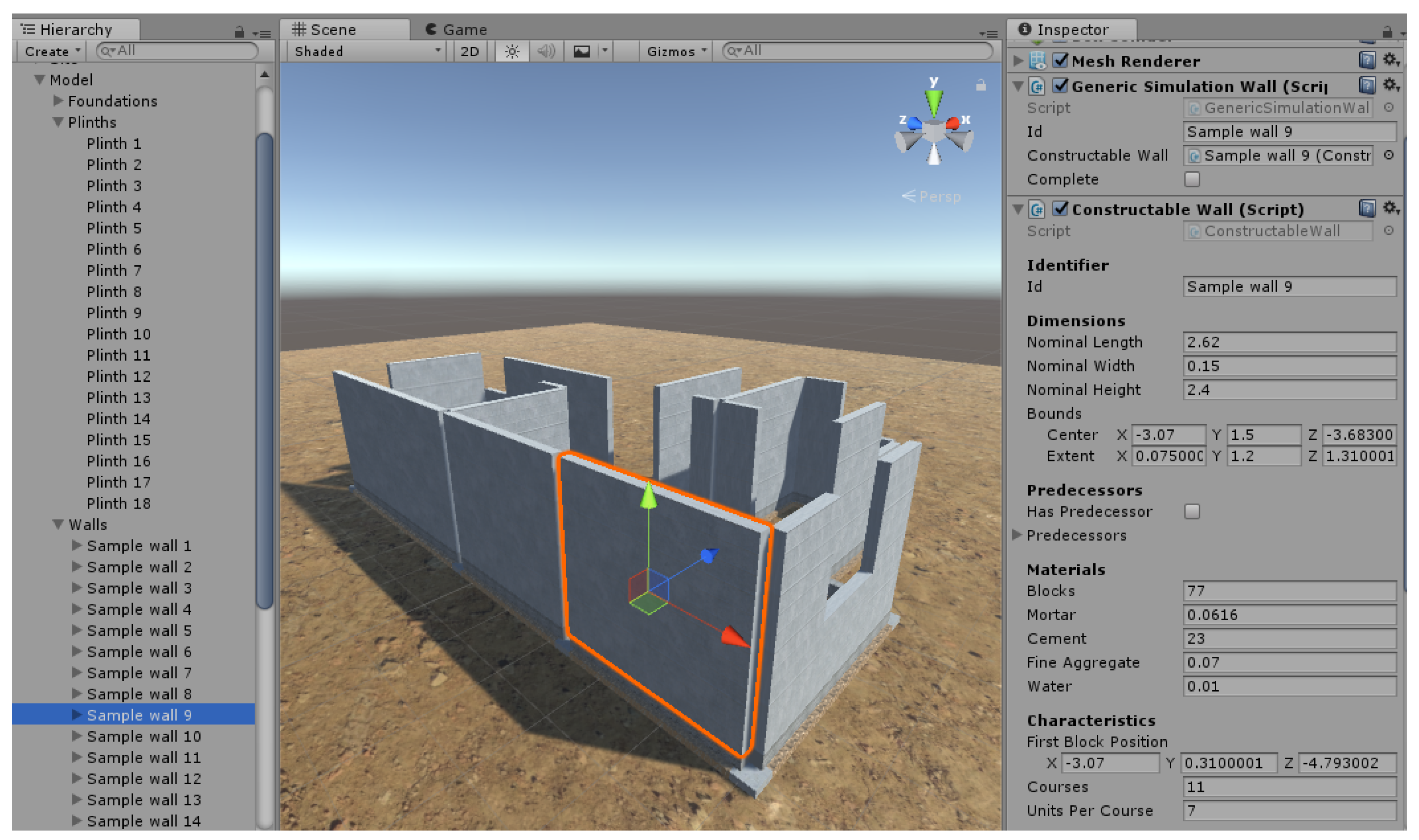
A model of the sample house that was built in the selected project was developed in Autodesk Revit (Version 2018) and imported into the scene as an fbx file. Once in the scene, scripts of the Constructable Element and generic simulation model types were attached to each game object representing masonry walls. Figure 13 shows the BIM model loaded into the scene and the attached scripts of the highlighted wall. The generic simulation models take as input the geometry and location of the walls, which are extracted from the BIM model. The geometry is used to calculate the required materials to complete the simulation. The location is used to calculate the distances between each wall and the material storage sites (defined in the environment) and to locate the concrete blocks and workers at the appropriate place during the animations.
6.5. Simulation Model
The simulation model of the selected construction project consists of 21 wall submodels. Each submodel is linked to the Main CU event of the distributed simulation component, which represents the control unit at the topmost level of the control structure hierarchy. When this event occurs, it sends a signal to each incomplete wall submodel. All the required materials are instantiated as game objects at the beginning of the simulation at storage locations predefined in the environment.
The selected construction activity was simulated for a random house from each zone using crews of a mason and a different number of helpers. Table 5 shows the different scenarios that were simulated to achieve the objective of the case study. Scenarios in which additional helpers did not decrease the average duration of the activity were not considered in the case study. Three simulation outcomes were observed in order to conclude about the different crew compositions: (1) The duration of the construction activity; (2) The waiting time of the mason; and (3) The walking distance per day of helpers. Each scenario was simulated fifty times and the results were compared to provide recommendations.
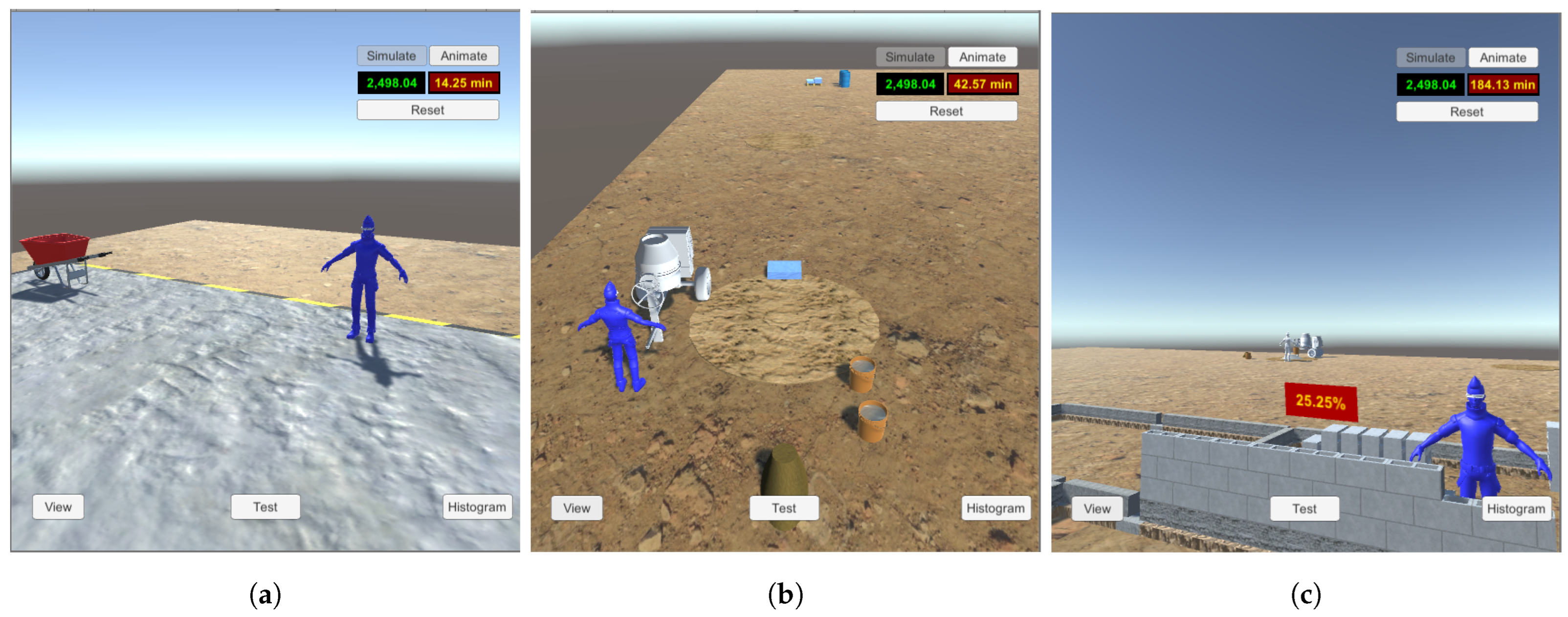
The model was validated using a combination of two techniques, animation and traces. The animation technique consists of graphically visualising the operational behaviour of the model as it moves through time, whereas in the traces technique, the behaviour of different types of entities in the model are followed through the model to determine if its logic is correct [43]. Validation was performed by visualising the simulation-based animation of a randomly selected run of each scenario and following the behaviour of workers. Figure 14 shows the location of a mason from a random run of Scenario 2 at different times.
6.6. Case Study Results
This case study did not attempt to draw generic conclusions from the obtained results that favour a crew composition over another. Its purpose was to demonstrate that the implemented framework enables the comparison of the performance of a construction project with different conditions without re-formalising the simulation model. This section presents the results of the observed simulation outcomes to illustrate the employment of the proposed framework.
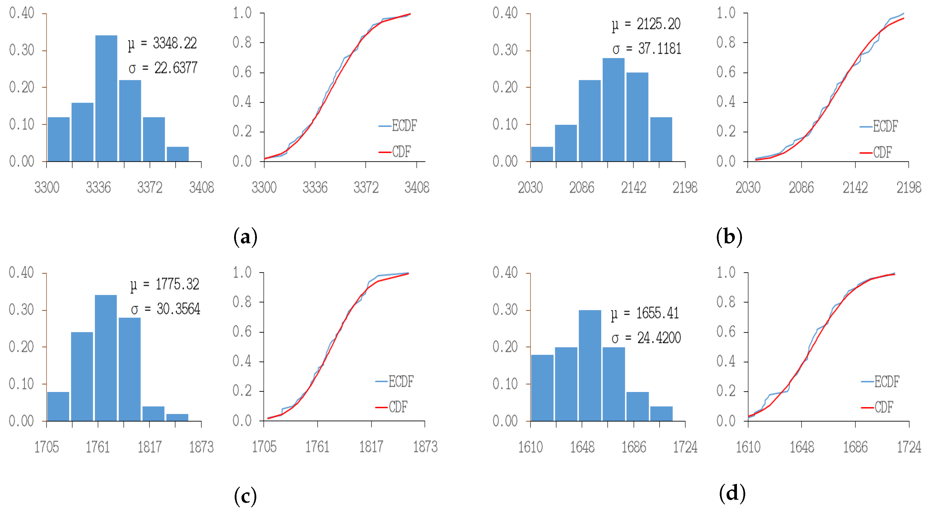
Figure 15 shows the activity durations obtained from the scenarios of Zone 3. The graphs on the left side of each subfigure show the frequency with which the durations were observed throughout the simulation runs, whereas those on the right side show a comparison between the empirical cumulative distribution function (ECDF) of the observed results and the normal cumulative distribution function (CDF). A Kolmogorov–Smirnov goodness-of-fit test [61] was applied to the obtained duration data sets. Results show that all the duration data sets follow normal distributions with a significance level of . Table 6 reports the simulation outputs observed for each scenario. Coupled with the animations, these results provide sufficient insights to support informed decision making. For example, in Scenarios 4 and 5, the average waiting time of the mason was similar, although the mean estimated duration was approximately 1.5 h shorter in the latter. The simulation-based animations of these scenarios reveal that when the mason requires preparing mortar, the materials arrive faster to the preparation site in Scenario 5 thanks to the availability of more helpers. With such insights, the model can support decision makers in deciding whether the cost of larger crews is worth gaining approximately 1.5 h per house in Zone 4.
7. Conclusions
The contribution of this article mainly lies in three aspects: (1) The proposed simulation modelling approach that leverages distributed simulation, hierarchical control structures, and parametric simulation modelling. This approach links an existing BIM model to generic simulation models of construction activities implemented as script game components within a game engine. Compared to traditional construction simulation modelling, the proposed approach enables model reuse and allows users to develop a construction simulation model that considers project-specific constraints, such as resource allocation, movements on the site, task location, and task interdependencies. It also produces simulation-based animations for different visualisation purposes, including model verification and validation. (2) The development of a framework that facilitates the development of a construction simulation model based on a BIM model. (3) The demonstration of the usefulness of the implemented framework as a planning tool.
The main limitations of this work and directions for future research include: (1) Extending the libraries of Constructable Elements and generic simulation models of construction activities in the environment module is challenging. However, as the libraries are built up, developing more complex simulation models would become easier. (2) The simulation-based animations produced in the visualisation module of the proposed framework can be improved to show the continuous motion of resources rather than their position at discrete points in time when events occurred.
Author Contributions
Conceptualization, C.A.O.-S.; methodology, C.A.O.-S.; software, C.A.O.-S.; validation, C.A.O.-S.; writing—original draft preparation, C.A.O.-S.; writing—review and editing, C.A.O.-S., E.P., W.T., J.N., C.K.; visualization, C.A.O.-S.; supervision, W.T.; project administration, C.A.O.-S. All authors have read and agreed to the published version of the manuscript.
Funding
This researcher was funded by the Mexican National Council of Science and Technology (Conacyt) PhD scholarship number 293596/438300.
Institutional Review Board Statement
Not applicable.
Informed Consent Statement
Not applicable.
Data Availability Statement
The data presented in this study are available on request from the corresponding author.
Conflicts of Interest
The authors declare no conflict of interest.
References
- AbouRizk, S.M.; Halpin, D.; Mohamed, Y.; Hermann, U. Research in modeling and simulation for improving construction engineering operations. J. Constr. Eng. Manag. 2011, 137, 843–852. [Google Scholar] [CrossRef]
- Hamdan, S.B.; Barkokebas, B.; Manrique, J.D.; Al-Hussein, M. A BIM-based simulation model for inventory management in panelized construction. In Proceedings of the 32nd International Symposium on Automation and Robotics in Construction and Mining (ISARC 2015), Oulu, Finland, 15–18 June 2015; IAARC Publications: Oulu, Finland, 2015; pp. 1–6. [Google Scholar] [CrossRef] [Green Version]
- AbouRizk, S.M. Role of simulation in construction engineering and management. J. Constr. Eng. Manag. 2010, 136, 1140–1153. [Google Scholar] [CrossRef]
- Law, A.M.; Kelton, W.D. Simulation Modeling and Analysis; McGraw-Hill: New York, NY, USA, 2000; Volume 3. [Google Scholar]
- Lee, D.E.; Yi, C.Y.; Lim, T.K.; Arditi, D. Integrated simulation system for construction operation and project scheduling. J. Comput. Civ. Eng. 2010, 24, 557–569. [Google Scholar] [CrossRef]
- Ebrahimy, Y.; AbouRizk, S.M.; Fernando, S.; Mohamed, Y. Simulation modeling and sensitivity analysis of a tunneling construction project’s supply chain. Eng. Constr. Archit. Manag. 2011, 18, 462–480. [Google Scholar] [CrossRef]
- Werner, M.; AbouRizk, S.M. Simulation case study: Modelling distinct breakdown events for a tunnel boring machine excavation. In Proceedings of the 2015 Winter Simulation Conference (WSC), Huntington Beach, CA, USA, 6–9 December 2015; pp. 3234–3245. [Google Scholar] [CrossRef]
- Osorio-Sandoval, C.A.; Zaragoza-Grifé, J.N.; Corona-Suárez, G.A.; González-Fajardo, J.A. Discrete Event Simulation Analysis of the Effect of Labor Absenteeism on the Duration of Construction Activities in Housing Projects. Int. J. Eng. Res. Appl. 2016, 6, 46–55. [Google Scholar]
- Seo, J.; Lee, S.; Seo, J. Simulation-based assessment of workers’ muscle fatigue and its impact on construction operations. J. Constr. Eng. Manag. 2016, 142, 04016063. [Google Scholar] [CrossRef]
- Larsson, R.; Rudberg, M. Impact of Weather Conditions on In Situ Concrete Wall Operations Using a Simulation-Based Approach. J. Constr. Eng. Manag. 2019, 145, 05019009. [Google Scholar] [CrossRef] [Green Version]
- Pereira, E.; Han, S.; AbouRizk, S.M. Integrating Case-Based Reasoning and Simulation Modeling for Testing Strategies to Control Safety Performance. J. Comput. Civ. Eng. 2018, 32, 04018047. [Google Scholar] [CrossRef]
- Baniassadi, F.; Alvanchi, A.; Mostafavi, A. A simulation-based framework for concurrent safety and productivity improvement in construction projects. Eng. Constr. Archit. Manag. 2018, 25, 1501–1515. [Google Scholar] [CrossRef]
- Zayed, T.M.; Halpin, D. Simulation of concrete batch plant production. J. Constr. Eng. Manag. 2001, 127, 132–141. [Google Scholar] [CrossRef]
- Zhang, C.; Zayed, T.; Hammad, A. Resource management of bridge deck rehabilitation: Jacques Cartier bridge case study. J. Constr. Eng. Manag. 2008, 134, 311–319. [Google Scholar] [CrossRef]
- Feng, K.; Lu, W.; Chen, S.; Wang, Y. An Integrated Environment–Cost–Time Optimisation Method for Construction Contractors Considering Global Warming. Sustainability 2018, 10, 4207. [Google Scholar] [CrossRef] [Green Version]
- Rahm, T.; Scheffer, M.; Thewes, M.; König, M.; Duhme, R. Evaluation of disturbances in mechanized tunneling using process simulation. Comput.-Aided Civ. Infrastruct. Eng. 2016, 31, 176–192. [Google Scholar] [CrossRef]
- Lee, S.; Behzadan, A.; Kandil, A.; Mohamed, Y. Grand challenges in simulation for the architecture, engineering, construction, and facility management industries. In Computing in Civil Engineering (2013); American Society of Civil Engineers: Los Angeles, CA, USA, 2013; pp. 773–785. [Google Scholar] [CrossRef] [Green Version]
- Leite, F.; Cho, Y.; Behzadan, A.H.; Lee, S.; Choe, S.; Fang, Y.; Akhavian, R.; Hwang, S. Visualization, information modeling, and simulation: Grand challenges in the construction industry. J. Comput. Civ. Eng. 2016, 30, 04016035. [Google Scholar] [CrossRef] [Green Version]
- Abdelmegid, M.; González, V.; Poshdar, M.; O’Sullivan, M.; Walker, C.; Ying, F. Barriers to adopting simulation modelling in construction industry. Autom. Constr. 2020, 111, 103046. [Google Scholar] [CrossRef]
- Eastman, C.; Teicholz, P.; Sacks, R.; Liston, K. BIM Handbook: A Guide to Building Information Modeling for Owners, Managers, Designers, Engineers and Contractors; John Wiley & Sons: Hoboken, NJ, USA, 2011. [Google Scholar]
- Azhar, S. Building information modeling (BIM): Trends, benefits, risks, and challenges for the AEC industry. Leadersh. Manag. Eng. 2011, 11, 241–252. [Google Scholar] [CrossRef]
- König, M.; Koch, C.; Habenicht, I.; Spieckermann, S. Intelligent BIM-based construction scheduling using discrete event simulation. In Proceedings of the 2012 Winter Simulation Conference (WSC), Berlin, Germany, 9–12 December 2012; pp. 1–12. [Google Scholar] [CrossRef] [Green Version]
- Wang, W.C.; Weng, S.W.; Wang, S.H.; Chen, C.Y. Integrating building information models with construction process simulations for project scheduling support. Autom. Constr. 2014, 37, 68–80. [Google Scholar] [CrossRef]
- Lu, W.; Olofsson, T. Building information modeling and discrete event simulation: Towards an integrated framework. Autom. Constr. 2014, 44, 73–83. [Google Scholar] [CrossRef]
- Liu, H.; Al-Hussein, M.; Lu, M. BIM-based integrated approach for detailed construction scheduling under resource constraints. Autom. Constr. 2015, 53, 29–43. [Google Scholar] [CrossRef]
- Chang, S.; Son, J.; Jeong, W.; Yi, J.S. BIM-integrated simulation of construction operation simulation for lean production management. In Proceedings of the 2015 Modular and Offsite Construction (MOC) Summit, Edmonton, AB, Canada, 19–21 May 2015; pp. 288–294. [Google Scholar]
- Wu, C.; Jiang, R.; Li, X. Integration of BIM and Computer Simulations in Modular Construction, A Case Study. In Proceedings of the 2016 Modular and Offsite Construction (MOC) Summit, Edmonton, AB, Canada, 29 September–1 October 2016; pp. 59–66. [Google Scholar] [CrossRef]
- Barkokebas, B.; Zhang, Y.; Ritter, C.; Al-Hussein, M. Building information modelling and simulation integration for modular construction manufacturing performance improvement. In Proceedings of the European Modeling and Simulation Symposium, Barcelona, Spain, 18–20 September 2017; pp. 409–415. [Google Scholar]
- Golzarpoor, H.; González, V.A.; O’Sullivan, M.; Shahbazpour, M.; Walker, C.G.; Poshdar, M. A non-queue-based paradigm in Discrete-Event-Simulation modelling for construction operations. Simul. Model. Pract. Theory 2017, 77, 49–67. [Google Scholar] [CrossRef]
- Wu, I.C.; Borrmann, A.; Beißert, U.; König, M.; Rank, E. Bridge construction schedule generation with pattern-based construction methods and constraint-based simulation. Adv. Eng. Inform. 2010, 24, 379–388. [Google Scholar] [CrossRef]
- Krantz, J.; Larsson, J.; Lu, W.; Olofsson, T. Assessing embodied energy and greenhouse gas emissions in infrastructure projects. Buildings 2015, 5, 1156–1170. [Google Scholar] [CrossRef] [Green Version]
- Jeong, W.; Chang, S.; Son, J.; Yi, J.S. BIM-integrated construction operation simulation for just-in-time production management. Sustainability 2016, 8, 1106. [Google Scholar] [CrossRef] [Green Version]
- Robinson, S.; Nance, R.E.; Paul, R.J.; Pidd, M.; Taylor, S.J. Simulation model reuse: Definitions, benefits and obstacles. Simul. Model. Pract. Theory 2004, 12, 479–494. [Google Scholar] [CrossRef]
- Kasputis, S.; Ng, H.C. Composable simulations. In Proceedings of the 2000 Winter Simulation Conference, Orlando, FL, USA, 10–13 December 2000; Volume 2, pp. 1577–1584. [Google Scholar] [CrossRef]
- Anagnostou, A.; Taylor, S.J. A distributed simulation methodological framework for OR/MS applications. Simul. Model. Pract. Theory 2017, 70, 101–119. [Google Scholar] [CrossRef] [Green Version]
- Taghaddos, H. Developing a Generic Resource Allocation Framework for Construction Simulation. Ph.D. Thesis, University of Alberta, Edmonton, AB, Canada, 2010. [Google Scholar] [CrossRef]
- Fu, F. Design and Analysis of Complex Structures. In Design and Analysis of Tall and Complex Structures; Butterworth-Heinemann: Oxford, UK, 2018; pp. 177–211. [Google Scholar] [CrossRef]
- Lee, G.; Sacks, R.; Eastman, C.M. Specifying parametric building object behavior (BOB) for a building information modeling system. Autom. Constr. 2006, 15, 758–776. [Google Scholar] [CrossRef]
- ALICE Technologies Inc. ALICE. Available online: https://www.alicetechnologies.com/ (accessed on 25 July 2022).
- BIM+. ALICE? Who the Heck is ALICE? 2021. Available online: https://www.bimplus.co.uk/alice-who-the-heck-is-alice/ (accessed on 25 July 2022).
- Al-Hussein, M.; Niaz, M.A.; Yu, H.; Kim, H. Integrating 3D visualization and simulation for tower crane operations on construction sites. Autom. Constr. 2006, 15, 554–562. [Google Scholar] [CrossRef]
- RazaviAlavi, S.; AbouRizk, S. Construction site layout planning using a Simulation-Based decision support tool. Logistics 2021, 5, 65. [Google Scholar] [CrossRef]
- Sargent, R.G. Verification and validation of simulation models. J. Simul. 2013, 7, 12–24. [Google Scholar] [CrossRef] [Green Version]
- ElNimr, A.A.; Mohamed, Y. Application of gaming engines in simulation driven visualization of construction operations. J. Inf. Technol. Constr. 2011, 16, 23–38. [Google Scholar]
- Kamat, V.R.; Martinez, J.C. Visualizing simulated construction operations in 3D. J. Comput. Civ. Eng. 2001, 15, 329–337. [Google Scholar] [CrossRef]
- Kamat, V.R.; Martinez, J.C. Validating complex construction simulation models using 3D visualization. Syst. Anal. Model. Simul. 2003, 43, 455–467. [Google Scholar] [CrossRef]
- Rekapalli, P.V.; Martinez, J.C. Discrete-event simulation-based virtual reality environments for construction operations: Technology introduction. J. Constr. Eng. Manag. 2010, 137, 214–224. [Google Scholar] [CrossRef]
- Chen, H.M.; Huang, P.H. 3D AR-based modeling for discrete-event simulation of transport operations in construction. Autom. Constr. 2013, 33, 123–136. [Google Scholar] [CrossRef]
- ElNimr, A.A.; Fagiar, M.; Mohamed, Y. Two-way integration of 3D visualization and discrete event simulation for modeling mobile crane movement under dynamically changing site layout. Autom. Constr. 2016, 68, 235–248. [Google Scholar] [CrossRef]
- Osorio-Sandoval, C.A.; Tizani, W.; Koch, C. A method for discrete event simulation and building information modelling integration using a game engine. Adv. Comput. Des. 2018, 3, 405–418. [Google Scholar] [CrossRef]
- Hevner, A.R.; March, S.T.; Park, J.; Ram, S. Design science in information systems research. MIS Q. 2004, 28, 75–105. [Google Scholar] [CrossRef] [Green Version]
- Furian, N.; O’Sullivan, M.; Walker, C.; Vössner, S.; Neubacher, D. A conceptual modeling framework for discrete event simulation using hierarchical control structures. Simul. Model. Pract. Theory 2015, 56, 82–96. [Google Scholar] [CrossRef]
- Anderson, E.F.; McLoughlin, L.; Watson, J.; Holmes, S.; Jones, P.; Pallett, H.; Smith, B. Choosing the infrastructure for entertainment and serious computer games-a whiteroom benchmark for game engine selection. In Proceedings of the 2013 5th International Conference on Games and Virtual Worlds for Serious Applications (VS-GAMES), Poole, UK, 11–13 September 2013; pp. 1–8. [Google Scholar] [CrossRef]
- Petridis, P.; Dunwell, I.; de Freitas, S.; Panzoli, D. An Engine Selection Methodology for High Fidelity Serious Games. In Proceedings of the 2010 Second International Conference on Games and Virtual Worlds for Serious Applications, Braga, Portugal, 25–26 March 2010; pp. 27–34. [Google Scholar] [CrossRef] [Green Version]
- Martinez, J.C. Methodology for conducting discrete-event simulation studies in construction engineering and management. J. Constr. Eng. Manag. 2009, 136, 3–16. [Google Scholar] [CrossRef]
- Akhavian, R.; Behzadan, A.H. An integrated data collection and analysis framework for remote monitoring and planning of construction operations. Adv. Eng. Inform. 2012, 26, 749–761. [Google Scholar] [CrossRef]
- Du, J.; Zou, Z.; Shi, Y.; Zhao, D. Zero latency: Real-time synchronization of BIM data in virtual reality for collaborative decision-making. Autom. Constr. 2018, 85, 51–64. [Google Scholar] [CrossRef]
- Unity Technologies. Unity—Manual: Unity User Manual (2019.1). 2019. Available online: https://docs.unity3d.com/2019.1/Documentation/Manual/UnityManual.html (accessed on 10 July 2020).
- Ceylan, A.; Gunal, M.M. A methodology for developing DES models: Event graphs and SharpSim. In Proceedings of the 23rd European Modeling & Simulation Symposium, Rome, Italy, 12–14 September 2011; pp. 278–282. [Google Scholar]
- Ruegg, C.; Cuda, M.; Van Gael, J. Math.Net Numerics Version 4.8.0. 2019. Available online: https://numerics.mathdotnet.com/ (accessed on 10 July 2020).
- Massey, F.J., Jr. The Kolmogorov-Smirnov test for goodness of fit. J. Am. Stat. Assoc. 1951, 46, 68–78. [Google Scholar] [CrossRef]
Figure 1.
Adopted simulation approach.

Figure 2.
Constructable element interface.

Figure 3.
Overview of the proposed framework.

Figure 4.
Resource class diagram.

Figure 5.
Flow diagram of the pre-processing module.

Figure 6.
Time advancement flow diagram.

Figure 7.
Class diagram of the distributed simulation component. This diagram uses standard UML notation: Hollow diamonds represent aggregation; filled diamonds represent composition; stars indicate multiplicity (1..* means that 1 or more instances of the child class are part of the parent class, * means that zero or more instances of the child class are part of the parent class).

Figure 8.
Federating a construction activity submodel into the simulation model of the project.

Figure 9.
Distributed simulation component sequence diagram.

Figure 10.
Case study site layout.

Figure 11.
Generic simulation model of the selected construction activity.

Figure 12.
Constructable Masonry Wall class diagram.

Figure 13.
BIM model of masonry walls loaded into scene.

Figure 14.
Resources at different points in time in Scenario 2. (a) Mason idle at time 14.25. (b) Mason preparing mortar at time 42.57. (c) Mason laying block at time 184.13.
Figure 14.
Resources at different points in time in Scenario 2. (a) Mason idle at time 14.25. (b) Mason preparing mortar at time 42.57. (c) Mason laying block at time 184.13.

Figure 15.
Simulation results from the scenarios of zone 3. (a) Scenario 6. (b) Scenario 7. (c) Scenario 8. (d) Scenario 9.
Figure 15.
Simulation results from the scenarios of zone 3. (a) Scenario 6. (b) Scenario 7. (c) Scenario 8. (d) Scenario 9.


Table 1.
Work breakdown structure of the modelled activity.
| Task | ID |
|---|---|
| Load blocks into wheelbarrow | MW-01 |
| Move blocks to wall construction site | MW-02 |
| Unload blocks in wall construction site | MW-03 |
| Load aggregate into wheelbarrow | MW-04 |
| Move aggregate to mortar prep site | MW-05 |
| Unload aggregate in mortar prep site | MW-06 |
| Load cement bag into wheelbarrow | MW-07 |
| Move cement bag to mortar prep site | MW-08 |
| Unload cement bag in mortar prep site | MW-09 |
| Fill bucket with water | MW-10 |
| Move water to mortar prep site | MW-11 |
| Prepare mortar | MW-12 |
| Fill bucket with mortar | MW-13 |
| Move mortar to wall construction site | MW-14 |
| Lay concrete block | MW-15 |
Table 2.
Decision making mechanism of control unit 1.
| Next Event | Conditions |
|---|---|
| CU-2 | mortar volume in preparation site < 0.02 |
| mortar prepared < mortar needed | |
| MW-01 | blocks in wall construction site < blocks needed |
| blocks in storage site > 0 | |
| MW-13 | mason ready to lay blocks needs mortar |
| volume of mortar in preparation site > 0 | |
| MW-15 | blocks in wall construction site > 0 |
| volume of mortar in preparation site > 0 |
Table 3.
Decision making mechanism of control unit 2.
| Next Event | Conditions |
|---|---|
| MW-04 | fine aggregate volume in mortar preparation site < 0.16 |
| MW-07 | cement bags in mortar preparation site < 1 |
| MW-10 | water buckets in mortar preparation site < 2 |
| MW-12 | fine aggregate volume in mortar preparation site ≥ 0.16 |
| cement bags in mortar preparation site ≥ 1 | |
| water buckets in mortar preparation site ≥ 2 |
Table 4.
Duration in minutes of masonry wall with concrete block tasks.
| ID | Tasks | Distribution | Parameters |
|---|---|---|---|
| D-01 | MW-01, MW-03 | Triangular | , , |
| D-02 ∗ | MW-02, MW-05, MW-08 | Triangular | , , |
| D-03 | MW-04 | Triangular | , , |
| D-04 | MW-06 | Triangular | , , |
| D-05 | MW-07, MW-09 | Triangular | , , |
| D-06 | MW-10, MW-13 | Deterministic | |
| D-07 | MW-11 | Deterministic | |
| D-08 | MW-12 | Normal | , |
| D-09 | MW-14 | Normal | , |
| D-10 | MW-15 | Weibull | , |
| D-11 ★ ∗ | Return | Triangular | , , |
∗ in minutes per metre. A sample from the distribution is multiplied by the distance travelled. ★ Return represents a helper returning to storage site with empty wheelbarrow
Table 5.
Modelled scenarios.
| Scenario ID | Zone ID | Average Distance to Storage Site (m) | Number of Masons | Number of Helpers |
|---|---|---|---|---|
| 1 | 4 | 670.93 | 1 | 1 |
| 2 | 4 | 670.93 | 1 | 2 |
| 3 | 4 | 670.93 | 1 | 3 |
| 4 | 4 | 670.93 | 1 | 4 |
| 5 | 4 | 670.92 | 1 | 5 |
| 6 | 3 | 470.93 | 1 | 1 |
| 7 | 3 | 470.93 | 1 | 2 |
| 8 | 3 | 470.93 | 1 | 3 |
| 9 | 3 | 470.93 | 1 | 4 |
| 10 | 2 | 320.93 | 1 | 1 |
| 11 | 2 | 320.93 | 1 | 2 |
| 12 | 2 | 320.93 | 1 | 3 |
| 13 | 1 | 120.93 | 1 | 1 |
| 14 | 1 | 120.93 | 1 | 2 |
Table 6.
Simulation results.
| Zone ID | Scenario ID | Duration (min) | Mason Waiting (min) | Helper Walking (km/day) ∗ |
|---|---|---|---|---|
| 4 | 1 | 4256.61 | 1644.22 | 12.44 |
| 2 | 2519.07 | 404.74 | 9.53 | |
| 3 | 1947.24 | 112.40 | 8.00 | |
| 4 | 1804.36 | 47.87 | 7.05 | |
| 5 | 1711.72 | 45.45 | 5.68 | |
| 3 | 6 | 3349.44 | 1149.85 | 10.85 |
| 7 | 2133.53 | 208.81 | 7.92 | |
| 8 | 1777.11 | 44.67 | 6.60 | |
| 9 | 1657.15 | 25.71 | 4.96 | |
| 2 | 10 | 2581.16 | 622.17 | 8.87 |
| 11 | 1778.35 | 89.50 | 6.75 | |
| 12 | 1611.93 | 22.72 | 4.47 | |
| 1 | 13 | 1802.66 | 201.62 | 4.90 |
| 14 | 1522.13 | 24.67 | 2.49 |
∗ Considering working days of 8 h.
Publisher’s Note: MDPI stays neutral with regard to jurisdictional claims in published maps and institutional affiliations. |
© 2022 by the authors. Licensee MDPI, Basel, Switzerland. This article is an open access article distributed under the terms and conditions of the Creative Commons Attribution (CC BY) license (https://creativecommons.org/licenses/by/4.0/).
Share and Cite
MDPI and ACS Style
Osorio-Sandoval, C.A.; Tizani, W.; Pereira, E.; Ninić, J.; Koch, C. Framework for BIM-Based Simulation of Construction Operations Implemented in a Game Engine. Buildings 2022, 12, 1199. https://doi.org/10.3390/buildings12081199
AMA Style
Osorio-Sandoval CA, Tizani W, Pereira E, Ninić J, Koch C. Framework for BIM-Based Simulation of Construction Operations Implemented in a Game Engine. Buildings. 2022; 12(8):1199. https://doi.org/10.3390/buildings12081199
Chicago/Turabian StyleOsorio-Sandoval, Carlos A., Walid Tizani, Estacio Pereira, Jelena Ninić, and Christian Koch. 2022. "Framework for BIM-Based Simulation of Construction Operations Implemented in a Game Engine" Buildings 12, no. 8: 1199. https://doi.org/10.3390/buildings12081199
Note that from the first issue of 2016, this journal uses article numbers instead of page numbers. See further details here.