The Spinning Voltage Influence on the Growth of ZnO-rGO Nanorods for Photocatalytic Degradation of Methyl Orange Dye

 , ,
, , 
Abstract
:1. Introduction
2. Results and Discussion
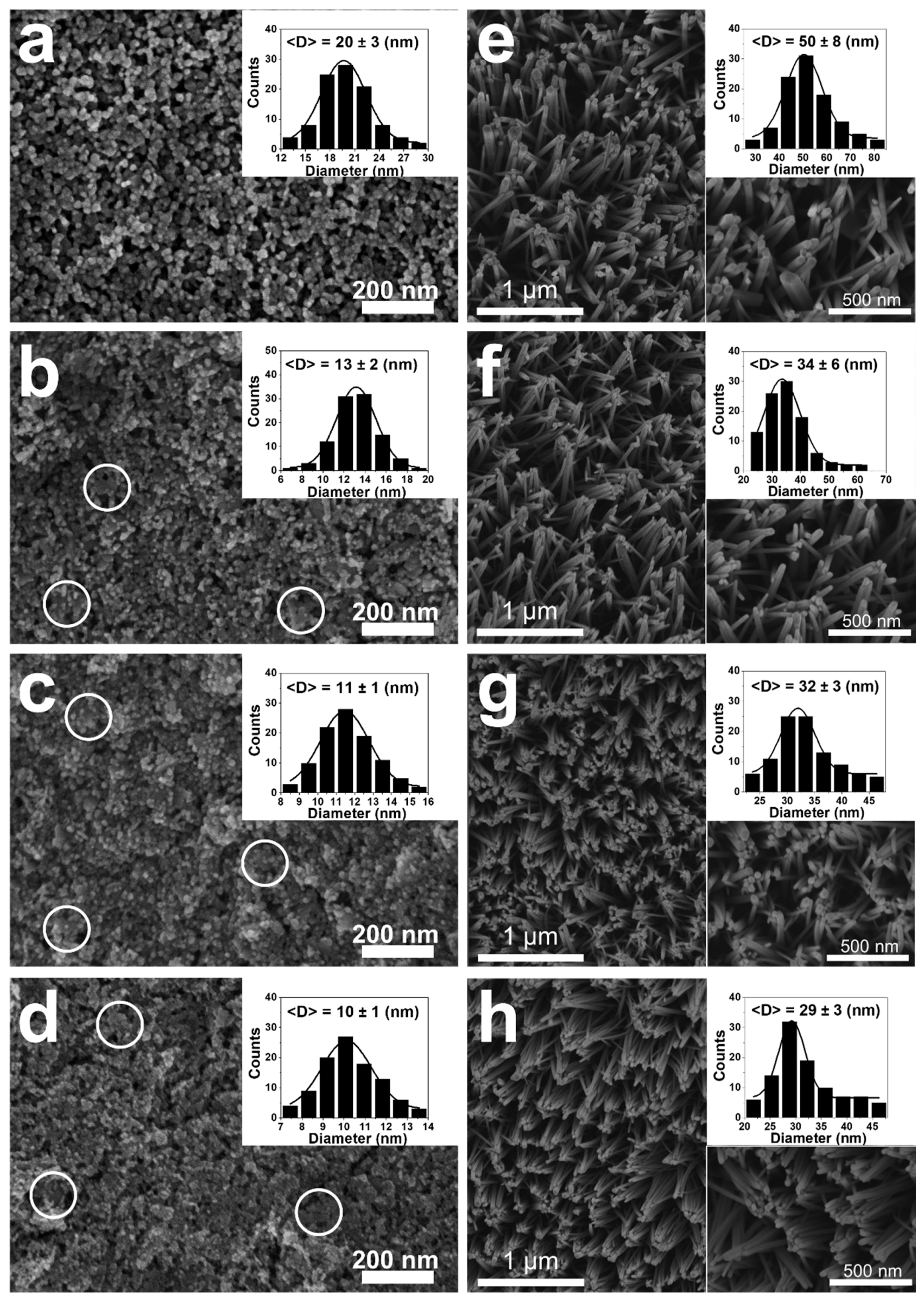
2.1. SEM Analysis
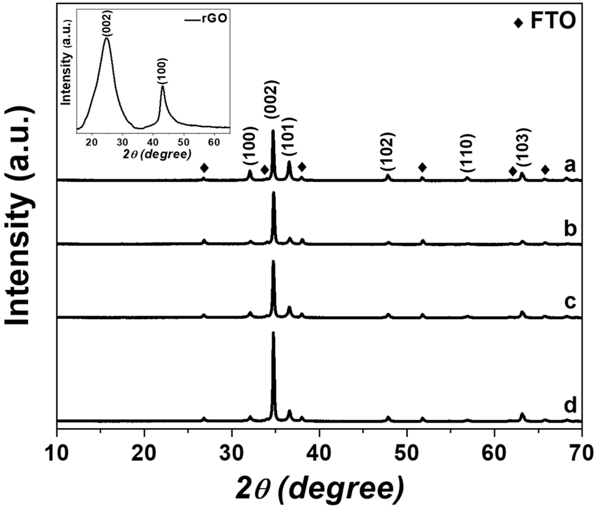
2.2. XRD Analysis
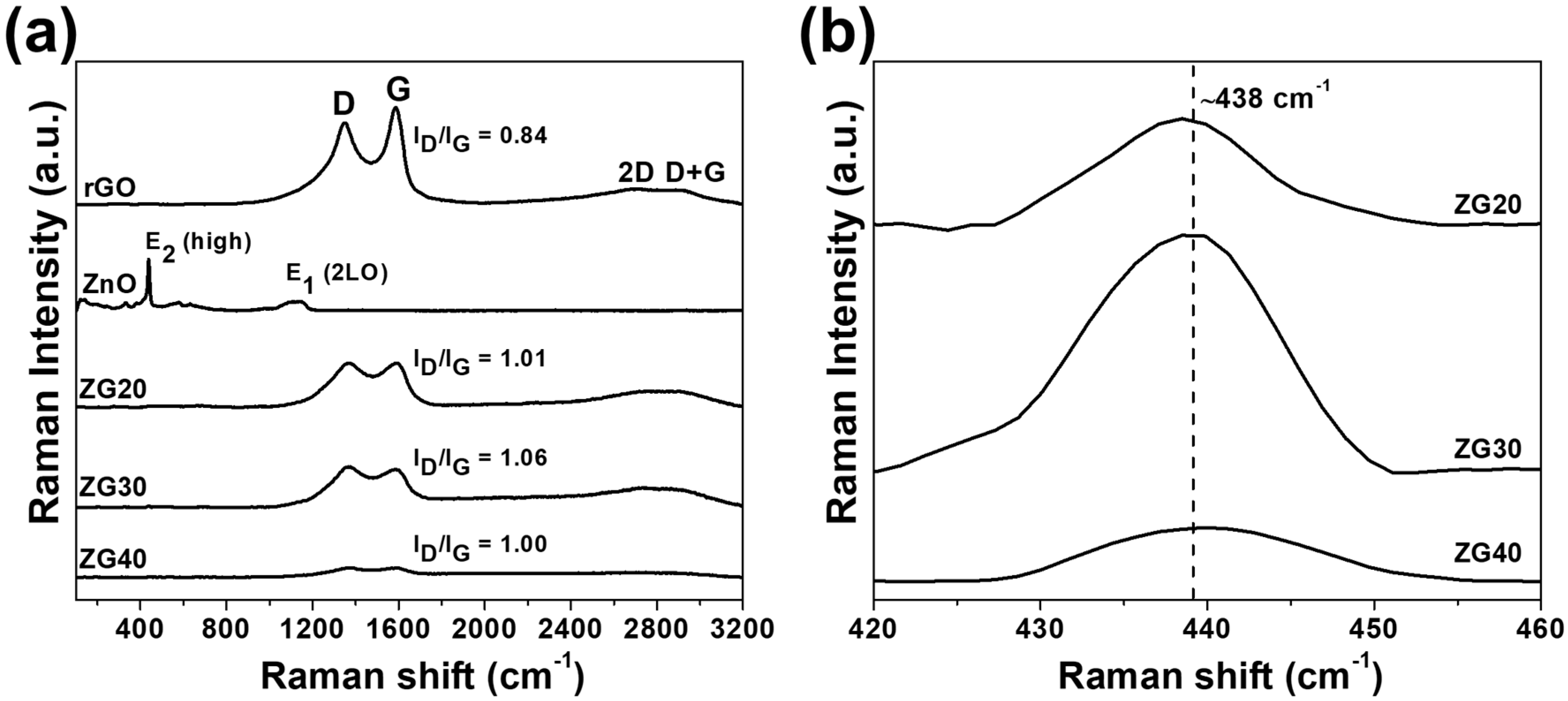
2.3. Raman Analysis
2.4. PL Analysis
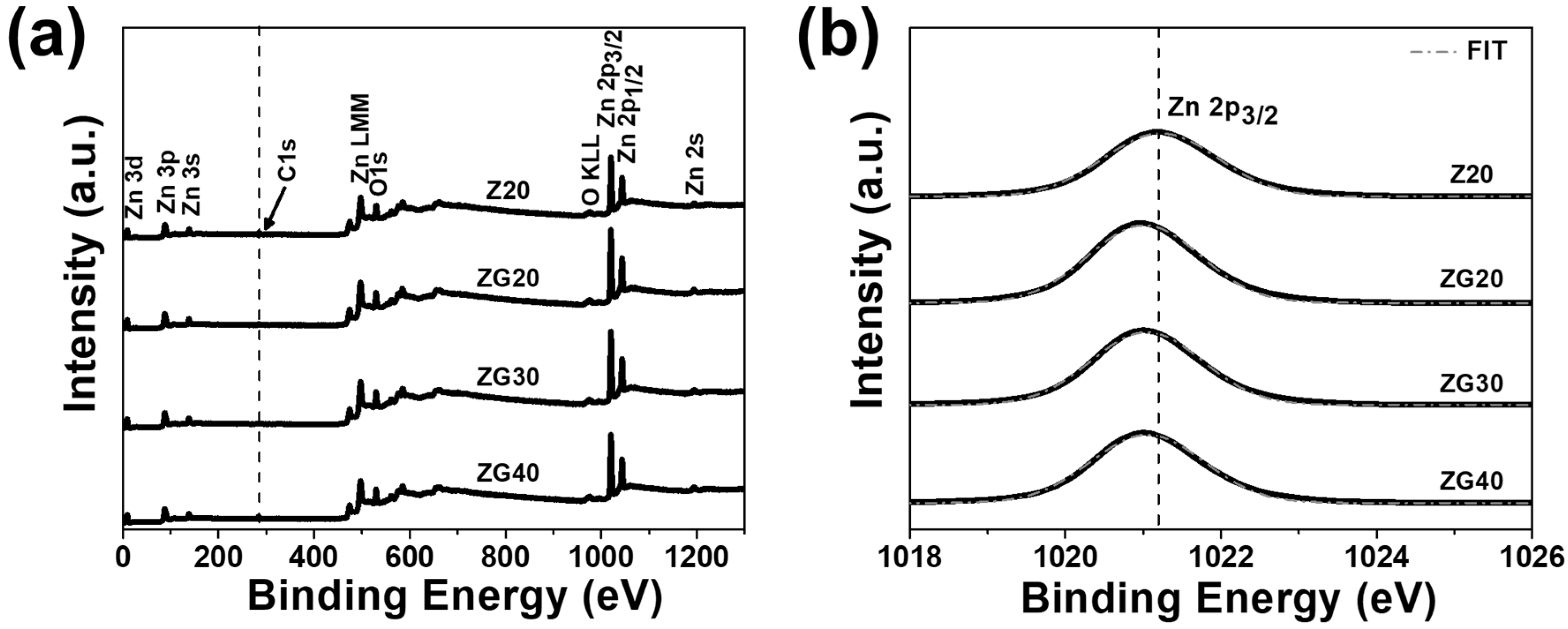
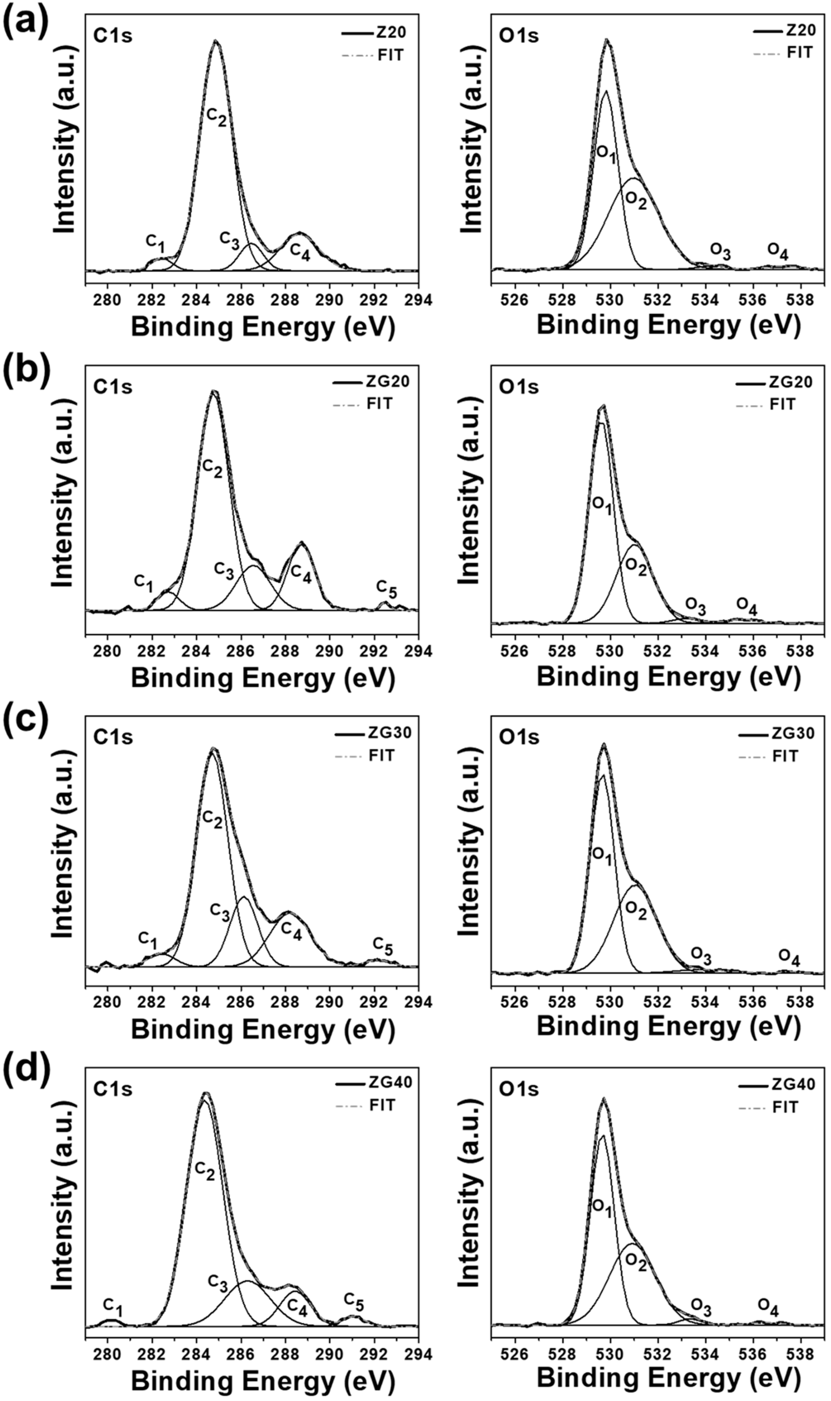
2.5. XPS Analysis
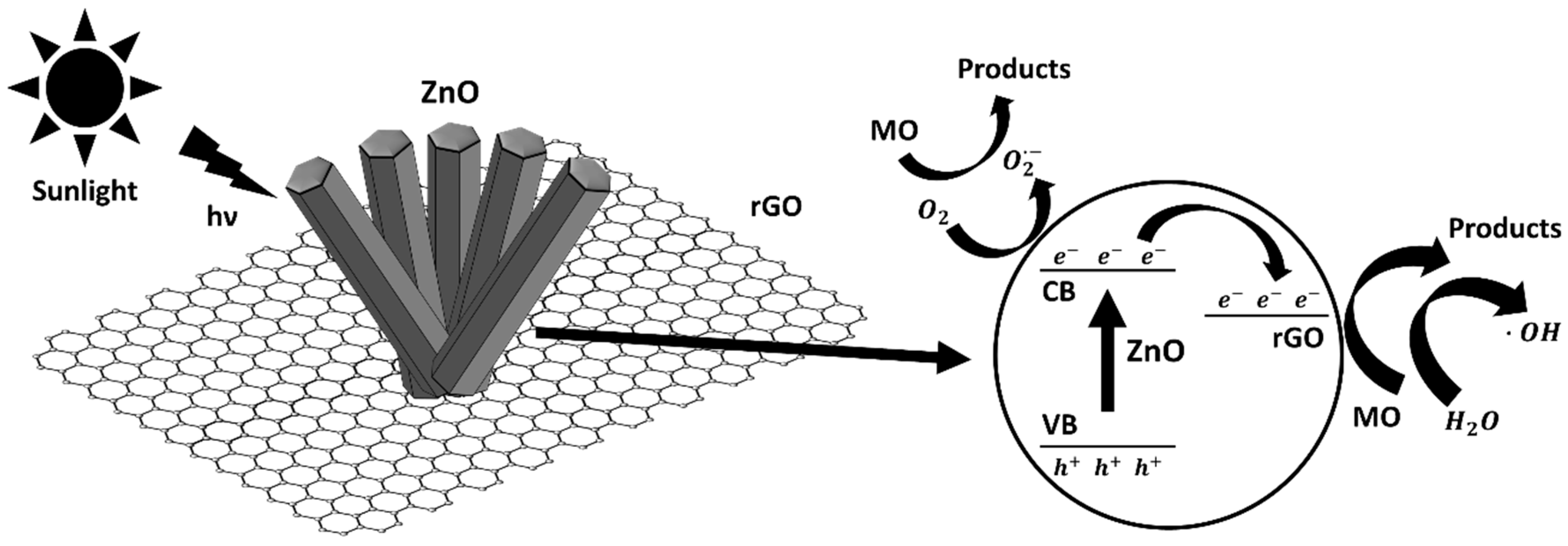
2.6. Photocatalytic Decolorization of Methyl Orange
3. Materials and Methods
3.1. Materials, Reagents, and Chemicals
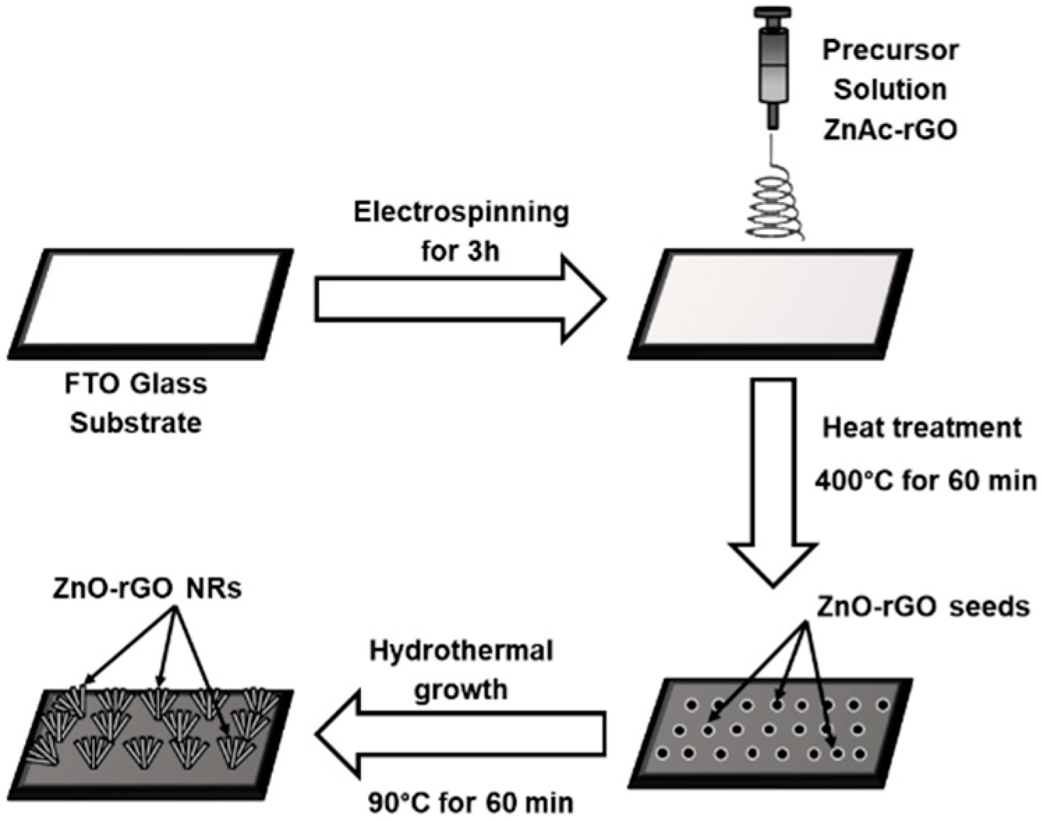
3.2. Preparation of ZnO and ZnO-rGO Nanorods
3.3. Photocatalytic Characterization
3.4. Characterization Methods
4. Conclusions
Author Contributions
Funding
Acknowledgments
Conflicts of Interest
References
- Hassaan, M.A.; Nemr, A.E. Health and environmental impacts of dyes: Mini review. Am. J. Environ. Sci. Eng. 2017, 1, 64–67. [Google Scholar] [CrossRef]
- Luan, M.; Jing, G.; Piao, Y.; Liu, D.; Jin, L. Treatment of refractory organic pollutants in industrial wastewater by wet air oxidation. Arab. J. Chem. 2017, 10, S769–S776. [Google Scholar] [CrossRef] [Green Version]
- Adeleye, A.S.; Conway, J.R.; Garner, K.; Huang, Y.; Su, Y.; Keller, A.A. Engineered nanomaterials for water treatment and remediation: Costs, benefits, and applicability. Chem. Eng. J. 2016, 286, 640–662. [Google Scholar] [CrossRef] [Green Version]
- Li, W.; Mu, B.; Yang, Y. Feasibility of industrial-scale treatment of dye wastewater via bio-adsorption technology. Bioresour. Technol. 2019, 277, 157–170. [Google Scholar] [CrossRef] [PubMed]
- Chaukura, N.; Murimba, E.C.; Gwenzi, W. Synthesis, characterisation and methyl orange adsorption capacity of ferric oxide–biochar nano-composites derived from pulp and paper sludge. Appl. Water Sci. 2017, 7, 2175–2186. [Google Scholar] [CrossRef] [Green Version]
- Vuono, D.; Catizzone, E.; Aloise, A.; Policicchio, A.; Agostino, R.G.; Migliori, M.; Giordano, G. Modelling of adsorption of textile dyes over multi-walled carbon nanotubes: Equilibrium and kinetic. Chin. J. Chem. Eng. 2017, 25, 523–532. [Google Scholar] [CrossRef]
- Guo, J.; Yuan, S.; Jiang, W.; Yue, H.; Cui, Z.; Liang, B. Adsorption and photocatalytic degradation behaviors of rhodamine dyes on surface-fluorinated TiO2 under visible irradiation. RSC Adv. 2016, 6, 4090–4100. [Google Scholar] [CrossRef]
- Natarajan, S.; Bajaj, H.C.; Tayade, R.J. Recent advances based on the synergetic effect of adsorption for removal of dyes from waste water using photocatalytic process. J. Environ. Sci. 2018, 65, 201–222. [Google Scholar] [CrossRef]
- Pastrana, E.C.; Zamora, V.; Wang, D.; Alarcón, H. Fabrication and characterization of α-Fe2O3/CuO heterostructure thin films via dip-coating technique for improved photoelectrochemical performance. Adv. Nat. Sci. Nanosci. Nanotechnol. 2019, 10, 035012. [Google Scholar] [CrossRef]
- Wang, L.; Zhao, J.; Liu, H.; Huang, J. Design, modification and application of semiconductor photocatalysts. J. Taiwan Inst. Chem. Eng. 2018, 93, 590–602. [Google Scholar] [CrossRef]
- Ani, I.J.; Akpan, U.G.; Olutoye, M.A.; Hameed, B.H. Photocatalytic degradation of pollutants in petroleum refinery wastewater by TiO2- and ZnO-based photocatalysts: Recent development. J. Clean. Prod. 2018, 205, 930–954. [Google Scholar] [CrossRef]
- Gandhi, A.C.; Yeoh, W.-S.; Wu, M.-A.; Liao, C.-H.; Chiu, D.-Y.; Yeh, W.-L.; Huang, Y.-L. New insights into the role of weak electron–phonon coupling in nanostructured zno thin films. Nanomaterials 2018, 8, 632. [Google Scholar] [CrossRef] [PubMed] [Green Version]
- Geetha, N.; Sivaranjani, S.; Ayeshamariam, A.; Kissinger, J.S.; Valan Arasu, M.; Jayachandran, M. ZnO doped oxide materials: Mini review. Fluid Mech. Open Access 2016, 3, 141. [Google Scholar] [CrossRef]
- Aliaga, J.; Cifuentes, N.; González, G.; Sotomayor-Torres, C.; Benavente, E. Enhancement photocatalytic activity of the heterojunction of two-dimensional hybrid semiconductors ZnO/V2O5. Catalysts 2018, 8, 374. [Google Scholar] [CrossRef] [Green Version]
- Dong, X.; Yang, P.; Liu, Y.; Jia, C.; Wang, D.; Wang, J.; Chen, L.; Che, Q. Morphology evolution of one-dimensional ZnO nanostructures towards enhanced photocatalysis performance. Ceram. Int. 2016, 42, 518–526. [Google Scholar] [CrossRef]
- Goel, S.; Kumar, B. A review on piezo-/ferro-electric properties of morphologically diverse ZnO nanostructures. J. Alloys Compd. 2020, 816, 152491. [Google Scholar] [CrossRef]
- Danwittayakul, S.; Songngam, S.; Sukkasi, S. Enhanced solar water disinfection using ZnO supported photocatalysts. Environ. Technol. 2018, 41, 349–356. [Google Scholar] [CrossRef]
- Dash, P.; Manna, A.; Mishra, N.C.; Varma, S. Synthesis and characterization of aligned ZnO nanorods for visible light photocatalysis. Physica E Low Dimens. Syst. Nanostruct. 2019, 107, 38–46. [Google Scholar] [CrossRef]
- Shankar, P.; Rayappan, J.B.B. Room temperature ethanol sensing properties of ZnO nanorods prepared using an electrospinning technique. J. Mater. Chem. C 2017, 5, 10869–10880. [Google Scholar] [CrossRef]
- Dong, X.; Yang, P.; Shi, R. Fabrication of ZnO nanorod arrays via electrospinning assisted hydrothermal method. Mater. Lett. 2014, 135, 96–98. [Google Scholar] [CrossRef]
- Kim, G.H.; An, T.; Lim, G. Fabrication of optical switching patterns with structural colored microfibers. Nanoscale Res. Lett. 2018, 13, 204. [Google Scholar] [CrossRef] [PubMed]
- Khojasteh, H.; Salavati-Niasari, M.; Sangsefidi, E.S. Photocatalytic evaluation of RGO/TiO2NWs/Pd-Ag nanocomposite as an improved catalyst for efficient dye degradation. J. Alloys Compd. 2018, 746, 611–618. [Google Scholar] [CrossRef]
- Kumar, S.; Pandit, V.; Bhattacharyya, K.; Krishnan, V. Sunlight driven photocatalytic reduction of 4-nitrophenol on Pt decorated ZnO-RGO nanoheterostructures. Mater. Chem. Phys. 2018, 214, 364–376. [Google Scholar] [CrossRef]
- Suave, J.; Amorim, S.M.; Ângelo, J.; Andrade, L.; Mendes, A.; Moreira, R.F.P.M. TiO2/reduced graphene oxide composites for photocatalytic degradation in aqueous and gaseous medium. J. Photochem. Photobiol. A Chem. 2017, 348, 326–336. [Google Scholar] [CrossRef]
- Ramos, P.G.; Flores, E.; Luyo, C.; Sánchez, L.A.; Rodriguez, J. Fabrication of ZnO-RGO nanorods by electrospinning assisted hydrothermal method with enhanced photocatalytic activity. Mater. Today Commun. 2019, 19, 407–412. [Google Scholar] [CrossRef]
- Su, B.; Dong, Y.; Jin, Z.; Wang, Q.; Lei, Z. Enhanced photocatalytic performance of ZnO/rGO composite materials prepared via an improved two-steps method. Ceram. Int. 2016, 42, 7632–7638. [Google Scholar] [CrossRef]
- Ong, C.B.; Mohammad, A.W.; Ng, L.Y.; Mahmoudi, E.; Azizkhani, S.; Hayati Hairom, N.H. Solar photocatalytic and surface enhancement of ZnO/rGO nanocomposite: Degradation of perfluorooctanoic acid and dye. Process Saf. Environ. Prot. 2017, 112, 298–307. [Google Scholar] [CrossRef]
- Vessalli, B.A.; Zito, C.A.; Perfecto, T.M.; Volanti, D.P.; Mazon, T. ZnO nanorods/graphene oxide sheets prepared by chemical bath deposition for volatile organic compounds detection. J. Alloys Compd. 2017, 696, 996–1003. [Google Scholar] [CrossRef] [Green Version]
- Rabieh, S.; Nassimi, K.; Bagheri, M. Synthesis of hierarchical ZnO–reduced graphene oxide nanocomposites with enhanced adsorption–photocatalytic performance. Mater. Lett. 2016, 162, 28–31. [Google Scholar] [CrossRef]
- Alver, U.; Zhou, W.; Belay, A.B.; Krueger, R.; Davis, K.O.; Hickman, N.S. Optical and structural properties of ZnO nanorods grown on graphene oxide and reduced graphene oxide film by hydrothermal method. Appl. Surf. Sci. 2012, 258, 3109–3114. [Google Scholar] [CrossRef]
- Theophile, N.; Jeong, H.K. Electrochemical properties of poly (vinyl alcohol) and graphene oxide composite for supercapacitor applications. Chem. Phys. Lett. 2017, 669, 125–129. [Google Scholar] [CrossRef]
- Haider, A.; Haider, S.; Kang, I.-K. A comprehensive review summarizing the effect of electrospinning parameters and potential applications of nanofibers in biomedical and biotechnology. Arab. J. Chem. 2018, 11, 1165–1188. [Google Scholar] [CrossRef]
- Ramos, P.G.; Morales, N.J.; Candal, R.J.; Hojamberdiev, M.; Rodriguez, J. Influence of zinc acetate content on the photoelectrochemical performance of zinc oxide nanostructures fabricated by electrospinning technique. Nanomater. Nanotechnol. 2016, 6, 1847980416663679. [Google Scholar] [CrossRef]
- Ramos, P.G.; Flores, E.; Sánchez, L.A.; Candal, R.J.; Hojamberdiev, M.; Estrada, W.; Rodriguez, J. Enhanced photoelectrochemical performance and photocatalytic activity of ZnO/TiO2 nanostructures fabricated by an electrostatically modified electrospinning. Appl. Surf. Sci. 2017, 426, 844–851. [Google Scholar] [CrossRef]
- Valério, L.R.; Mamani, N.C.; de Zevallos, A.O.; Mesquita, A.; Bernardi, M.I.B.; Doriguetto, A.C.; de Carvalho, H.B. Preparation and structural-optical characterization of dip-coated nanostructured Co-doped ZnO dilute magnetic oxide thin films. RSC Adv. 2017, 7, 20611–20619. [Google Scholar] [CrossRef] [Green Version]
- Yu, L.; Wang, L.; Sun, X.; Ye, D. Enhanced photocatalytic activity of rGO/TiO2 for the decomposition of formaldehyde under visible light irradiation. J. Environ. Sci. 2018, 73, 138–146. [Google Scholar] [CrossRef]
- Azmy, N.A.N.; Bakar, A.A.A.; Arsad, N.; Idris, S.; Mohmad, A.R.; Hamid, A.A. Enhancement of ZnO-rGO nanocomposite thin films by gamma radiation for E. coli sensor. Appl. Surf. Sci. 2017, 392, 1134–1143. [Google Scholar] [CrossRef]
- Ma, D.; Zhang, Y.; Gao, M.; Xin, Y.; Wu, J.; Bao, N. RGO/InVO4 hollowed-out nanofibers: Electrospinning synthesis and its application in photocatalysis. Appl. Surf. Sci. 2015, 353, 118–126. [Google Scholar] [CrossRef]
- Mwankemwa, B.S.; Nambala, F.J.; Kyeyune, F.; Hlatshwayo, T.T.; Nel, J.M.; Diale, M. Influence of ammonia concentration on the microstructure, electrical and raman properties of low temperature chemical bath deposited ZnO nanorods. Mater. Sci. Semicond. Process. 2017, 71, 209–216. [Google Scholar] [CrossRef] [Green Version]
- Kumar, P.; Som, S.; Pandey, M.K.; Das, S.; Chanda, A.; Singh, J. Investigations on optical properties of ZnO decorated graphene oxide (ZnO@ GO) and reduced graphene oxide (ZnO@ r-GO). J. Alloys Compd. 2018, 744, 64–74. [Google Scholar] [CrossRef]
- Khranovskyy, V.; Sendova, M.; Hosterman, B.; McGinnis, N.; Shtepliuk, I.; Yakimova, R. Temperature dependent study of basal plane stacking faults in Ag:ZnO nanorods by Raman and photoluminescence spectroscopy. Mater. Sci. Semicond. Process. 2017, 69, 62–67. [Google Scholar] [CrossRef]
- Iskandar, F.; Abdillah, O.B.; Stavila, E.; Aimon, A.H. The influence of copper addition on the electrical conductivity and charge transfer resistance of reduced graphene oxide (rGO). New. J. Chem. 2018, 42, 16362–16371. [Google Scholar] [CrossRef]
- Pandey, A.; Qureshi, A. Surface modified graphene oxide nanosheets by gold ion implantation as a substrate for surface enhanced Raman scattering. J. Alloys Compd. 2017, 703, 500–507. [Google Scholar] [CrossRef]
- Romeiro, F.C.; Rodrigues, M.A.; Silva, L.A.J.; Catto, A.C.; da Silva, L.F.; Longo, E.; Nossol, E.; Lima, R.C. rGO-ZnO nanocomposites for high electrocatalytic effect on water oxidation obtained by microwave-hydrothermal method. Appl. Surf. Sci. 2017, 423, 743–751. [Google Scholar] [CrossRef] [Green Version]
- Nguyen, V.Q.; Baynosa, M.L.; Nguyen, V.H.; Tuma, D.; Lee, Y.R.; Shim, J.-J. Solvent-driven morphology-controlled synthesis of highly efficient long-life ZnO/graphene nanocomposite photocatalysts for the practical degradation of organic wastewater under solar light. Appl. Surf. Sci. 2019, 486, 37–51. [Google Scholar] [CrossRef]
- Sharma, R.; Alam, F.; Sharma, A.K.; Dutta, V.; Dhawan, S.K. ZnO anchored graphene hydrophobic nanocomposite-based bulk heterojunction solar cells showing enhanced short-circuit current. J. Mater. Chem. C 2014, 2, 8142–8151. [Google Scholar] [CrossRef] [Green Version]
- Wu, X.; Zhang, X.; Zhao, C.; Qian, X. One-pot hydrothermal synthesis of ZnO/RGO/ZnO@ Zn sensor for sunset yellow in soft drinks. Talanta 2018, 179, 836–844. [Google Scholar] [CrossRef]
- Chakraborty, A.; Pizzoferrato, R.; Agresti, A.; De Matteis, F.; Orsini, A.; Medaglia, P.G. Wet-chemical synthesis of ZnO nanowires on low-temperature photo-activated ZnO-rGO composite thin film with enhanced photoconduction. J. Electron. Microsc. 2018, 47, 5863–5869. [Google Scholar] [CrossRef]
- Jayalakshmi, G.; Saravanan, K.; Pradhan, J.; Magudapathy, P.; Panigrahi, B.K. Facile synthesis and enhanced luminescence behavior of ZnO: Reduced graphene oxide (rGO) hybrid nanostructures. J. Lumin. 2018, 203, 1–6. [Google Scholar] [CrossRef]
- Panigrahy, B.; Sarma, D.D. Enhanced photocatalytic efficiency of AuPd nanoalloy decorated ZnO-reduced graphene oxide nanocomposites. RSC Adv. 2015, 5, 8918–8928. [Google Scholar] [CrossRef]
- Pascariu, P.; Homocianu, M. ZnO-based ceramic nanofibers: Preparation, properties and applications. Ceram. Int. 2019, 45, 11158–11173. [Google Scholar] [CrossRef]
- Lozada, E.V.; González, G.M.C.; Torchynska, T. Photoluminescence emission and structure diversity in ZnO:Ag nanorods. J. Phys. Conf. Ser. 2015, 582, 012031. [Google Scholar] [CrossRef]
- Othman, A.A.; Osman, M.A.; Abd-Elrahim, A.G. The effect of milling time on structural, optical and photoluminescence properties of ZnO nanocrystals. Optik 2018, 156, 161–168. [Google Scholar] [CrossRef]
- Bolaghi, Z.K.; Masoudpanah, S.M.; Hasheminiasari, M. Photocatalytic activity of ZnO/RGO composite synthesized by one-pot solution combustion method. Mater. Res. Bull. 2019, 115, 191–195. [Google Scholar] [CrossRef]
- Jiang, H.; Zhang, X.; Gu, W.; Feng, X.; Zhang, L.; Weng, Y. Synthesis of ZnO particles with multi-layer and biomorphic porous microstructures and ZnO/rGO composites and their applications for photocatalysis. Chem. Phys. Lett. 2018, 711, 100–106. [Google Scholar] [CrossRef]
- Zhou, Y.; Li, D.; Yang, L.; Li, C.; Liu, Y.; Lu, J.; Wang, Y. Preparation of 3D urchin-like RGO/ZnO and its photocatalytic activity. J. Mater. Sci: Mater. Electron. 2017, 28, 7935–7942. [Google Scholar] [CrossRef]
- Wu, Y.; Zhang, L.; Zhou, Y.; Zhang, L.; Li, Y.; Liu, Q.; Hu, J.; Yang, J. Light-induced ZnO/Ag/rGO bactericidal photocatalyst with synergistic effect of sustained release of silver ions and enhanced reactive oxygen species. Chin. J. Catal. 2019, 40, 691–702. [Google Scholar] [CrossRef]
- Neena, D.; Kondamareddy, K.K.; Humayun, M.; Mohan, V.B.; Lu, D.; Fu, D.; Gao, W. Fabrication of ZnO/N-rGO composite as highly efficient visible-light photocatalyst for 2, 4-DCP degradation and H2 evolution. Appl. Surf. Sci. 2019, 488, 611–619. [Google Scholar] [CrossRef]
- Shanmugasundaram, A.; Boppella, R.; Jeong, Y.-J.; Park, J.; Kim, Y.-B.; Choi, B.; Park, S.H.; Jung, S.; Lee, D.-W. Facile in-situ formation of rGO/ZnO nanocomposite: Photocatalytic remediation of organic pollutants under solar illumination. Mater. Chem. Phys. 2018, 218, 218–228. [Google Scholar] [CrossRef]
- Liu, X.; Wang, L.-S.; Ma, Y.; Qiu, Y.; Xie, Q.; Chen, Y.; Peng, D.-L. Facile synthesis and microwave absorption properties of yolk-shell ZnO-Ni-C/RGO composite materials. Chem. Eng. J. 2018, 333, 92–100. [Google Scholar] [CrossRef]
- Yusoff, F.; Khing, N.T.; Hao, C.C.; Sang, L.P.; Muhamad, N.B.; Saleh, N.M. The electrochemical behavior of Zinc oxide/reduced graphene oxide composite electrode in dopamine. Malays. J. Anal. Sci. 2018, 22, 227–237. [Google Scholar] [CrossRef]
- Kumbhakar, P.; Pramanik, A.; Biswas, S.; Kole, A.K.; Sarkar, R.; Kumbhakar, P. In-situ synthesis of rGO-ZnO nanocomposite for demonstration of sunlight driven enhanced photocatalytic and self-cleaning of organic dyes and tea stains of cotton fabrics. J. Hazard. Mater. 2018, 360, 193–203. [Google Scholar] [CrossRef] [PubMed]
- Qu, G.; Fan, G.; Zhou, M.; Rong, X.; Li, T.; Zhang, R.; Sun, J.; Chen, D. Graphene-modified ZnO nanostructures for low-temperature NO2 sensing. ACS Omega 2019, 4, 4221–4232. [Google Scholar] [CrossRef] [Green Version]
- Luo, J.; Yan, Z.; Liu, R.; Xu, J.; Wang, X. Synthesis and excellent visible light photocatalysis performance of magnetic reduced graphene oxide/ZnO/ZnFe2O4 composites. RSC Adv. 2017, 7, 23246–23254. [Google Scholar] [CrossRef] [Green Version]
- Bernal, V.; Giraldo, L.; Moreno-Piraján, J.C. Physicochemical properties of activated carbon: Their effect on the adsorption of pharmaceutical compounds and adsorbate-adsorbent interactions. C J. Carbon Res. 2018, 4, 62. [Google Scholar] [CrossRef] [Green Version]
- Yang, T.; Sun, B.; Ni, L.; Wei, X.; Guo, T.; Shi, Z.; Han, F.; Duan, L. The mechanism of photocurrent enhancement of ZnO ultraviolet photodetector by reduced graphene oxide. Curr. Appl. Phys. 2018, 18, 859–863. [Google Scholar] [CrossRef]
- Abbas, K.N.; Bidin, N. Morphological driven photocatalytic activity of ZnO nanostructures. Appl. Surf. Sci. 2017, 394, 498–508. [Google Scholar] [CrossRef]
- Sudrajat, H.; Sujaridworakun, P. Correlation between particle size of Bi2O3 nanoparticles and their photocatalytic activity for degradation and mineralization of atrazine. J. Mol. Liq. 2017, 242, 433–440. [Google Scholar] [CrossRef]
- Parnicka, P.; Mazierski, P.; Grzyb, T.; Lisowski, W.; Kowalska, E.; Ohtani, B.; Zaleska-Medynska, A.; Nadolna, J. Influence of the preparation method on the photocatalytic activity of Nd-modified TiO2. Beilstein J. Nanotechnol. 2018, 9, 447–459. [Google Scholar] [CrossRef] [Green Version]
- Yu, J.; Huang, T.; Jiang, Z.; Sun, M.; Tang, C. Synthesis and characterizations of zinc oxide on reduced graphene oxide for high performance electrocatalytic reduction of oxygen. Molecules 2018, 23, 3227. [Google Scholar] [CrossRef] [Green Version]
- Harish, S.; Murugesan, G.; Archana, J.; Navaneethan, M.; Ponnusamy, S.; Muthamizhchelvan, C.; Shimomura, M.; Hayakawa, Y. Effect of organic ligand on ZnO nanostructures and to investigate the photocatalytic activity under visible light illumination. Mater. Sci. Semicond. Process. 2019, 103, 104608. [Google Scholar] [CrossRef]
- Labhane, P.K.; Patle, L.B.; Huse, V.R.; Sonawane, G.H.; Sonawane, S.H. Synthesis of reduced graphene oxide sheets decorated by zinc oxide nanoparticles: Crystallographic, optical, morphological and photocatalytic study. Chem. Phys. Lett. 2016, 661, 13–19. [Google Scholar] [CrossRef]
- Prabhu, S.; Megala, S.; Harish, S.; Navaneethan, M.; Maadeswaran, P.; Sohila, S.; Ramesh, R. Enhanced photocatalytic activities of ZnO dumbbell/reduced graphene oxide nanocomposites for degradation of organic pollutants via efficient charge separation pathway. Appl. Surf. Sci. 2019, 487, 1279–1288. [Google Scholar] [CrossRef]
- Mohamed, H.H. Sonochemical synthesis of ZnO hollow microstructure/reduced graphene oxide for enhanced sunlight photocatalytic degradation of organic pollutants. J. Photochem. Photobiol. A Chem. 2018, 353, 401–408. [Google Scholar] [CrossRef]
- Rodríguez, J.; Feuillet, G.; Donatini, F.; Onna, D.; Sanchez, L.; Candal, R.; Marchi, M.C.; Bilmes, S.A.; Chandezon, F. Influence of the spray pyrolysis seeding and growth parameters on the structure and optical properties of ZnO nanorod arrays. Mater. Chem. Phys. 2015, 151, 378–384. [Google Scholar] [CrossRef]


© 2020 by the authors. Licensee MDPI, Basel, Switzerland. This article is an open access article distributed under the terms and conditions of the Creative Commons Attribution (CC BY) license (http://creativecommons.org/licenses/by/4.0/).
Share and Cite
Ramos, P.G.; Luyo, C.; Sánchez, L.A.; Gomez, E.D.; Rodriguez, J.M. The Spinning Voltage Influence on the Growth of ZnO-rGO Nanorods for Photocatalytic Degradation of Methyl Orange Dye. Catalysts 2020, 10, 660. https://doi.org/10.3390/catal10060660
Ramos PG, Luyo C, Sánchez LA, Gomez ED, Rodriguez JM. The Spinning Voltage Influence on the Growth of ZnO-rGO Nanorods for Photocatalytic Degradation of Methyl Orange Dye. Catalysts. 2020; 10(6):660. https://doi.org/10.3390/catal10060660
Chicago/Turabian StyleRamos, Pierre G., Clemente Luyo, Luis A. Sánchez, Enrique D. Gomez, and Juan M. Rodriguez. 2020. "The Spinning Voltage Influence on the Growth of ZnO-rGO Nanorods for Photocatalytic Degradation of Methyl Orange Dye" Catalysts 10, no. 6: 660. https://doi.org/10.3390/catal10060660