Autonomous Mapping and Exploration with Unmanned Aerial Vehicles Using Low Cost Sensors †


1
Division of Human Mechanical Systems and Design, Faculty of Engineering, Hokkaido University, Sapporo, Hokkaido 060-8628, Japan
2
School of Regional Innovation and Social Design Engineering, Faculty of Engineering, Kitami Institute of Technology, Kitami, Hokkaido 090-8507, Japan
*
Author to whom correspondence should be addressed.
†
Presented at the 5th International Electronic Conference on Sensors and Applications, 15–30 November 2018; Available online: https://ecsa-5.sciforum.net.
‡
These authors contributed equally to this work.
Proceedings 2019, 4(1), 44; https://doi.org/10.3390/ecsa-5-05753
Published: 14 November 2018
(This article belongs to the Proceedings of 5th International Electronic Conference on Sensors and Applications)
Abstract
:Mapping and exploration are important tasks of mobile robots for various applications such as search and rescue, inspection, and surveillance. Unmanned aerial vehicles (UAVs) are more suited for such tasks because they have a large field of view compared to ground robots. Autonomous operation of UAVs is desirable for exploration in unknown environments. In such environments, the UAV must make a map of the environment and simultaneously localize itself in it which is commonly known as the SLAM (simultaneous localization and mapping) problem. This is also required to safely navigate between open spaces, and make informed decisions about the exploration targets. UAVs have physical constraints including limited payload, and are generally equipped with low-spec embedded computational devices and sensors. Therefore, it is often challenging to achieve robust SLAM on UAVs which also affects exploration. In this paper, we present an autonomous exploration of UAVs in completely unknown environments using low cost sensors such as LIDAR and an RGBD camera. A sensor fusion method is proposed to build a dense 3D map of the environment. Multiple images from the scene are geometrically aligned as the UAV explores the environment, and then a frontier exploration technique is used to search for the next target in the mapped area to explore the maximum area possible. The results show that the proposed algorithm can build precise maps even with low-cost sensors, and explore the environment efficiently.
1. Introduction
Exploration and mapping in unknown environments is a crucial task for intelligent robots to achieve complete autonomous behaviour. Recent advances in unmanned aerial vehicles (UAVs) have allowed mapping and exploration in difficult to access areas that were previously not possible using unmanned ground vehicles. UAVs have been deployed in areas that are deemed dangerous for human operation, and provide important information about the environment in applications such as search and rescue, site inspection, victim search in disaster situations, and monitoring. UAVs must be designed to operate autonomously with no prior information about the environment [1,2]. To navigate in such environments, the UAV must be capable of doing simultaneous localization and mapping (SLAM) as it explores the area. This is important, as the information perceived is utilized to safely navigate between free spaces and allows intelligent exploration of areas that were not previously mapped. Many variants of SLAM techniques have been successfully implemented in the past that use different sensors and the data is fused to provide informed decisions about the environment [3,4,5,6,7]. However, this puts a lot of constraint on the design aspect of the UAV, due to the limited payload capacity, and onboard computation, affecting the total flight time. Another problem occurs when the UAV is exploring in GPS denied environments such as indoor environments, and has to completely rely on the onboard sensors for localization and navigation. Mobile robot exploration in indoor environments has been extensively researched in the past and there are many existing techniques available primarily for ground robots, which include multi-robot systems [8,9,10]. Exploration using UAVs on the other hand is challenging due to 6 degree of freedom (DOF) motion control. Thus, there is a need of compact unmanned aerial systems (UASs).
In this paper, we introduce a UAS with low cost RGB-D sensor, a specific type of depth sensing devices that work in association with a RGB camera, that are able to augment the conventional image with depth information (related with the distance to the sensor) in a per-pixel basis for the purpose of mapping and exploration of unknown indoor environments. RGB-D sensors are used as primary sensor for mapping, since it can provide fairly accurate 3D information about the scene. Also, images from the camera can be utilized to navigate the UAV from ground station control in cases when the autonomous operation is not possible. The images from the camera are used for matching previously visited scenes and enhance the consistency of the map that has been built. A frontier based exploration strategy is used to cover the maximum possible region of the map. We present the proposed system by simulating an actual UAV and exploring in complex indoor environment using a robot operating system (ROS) and Gazebo.
2. Simulation Design
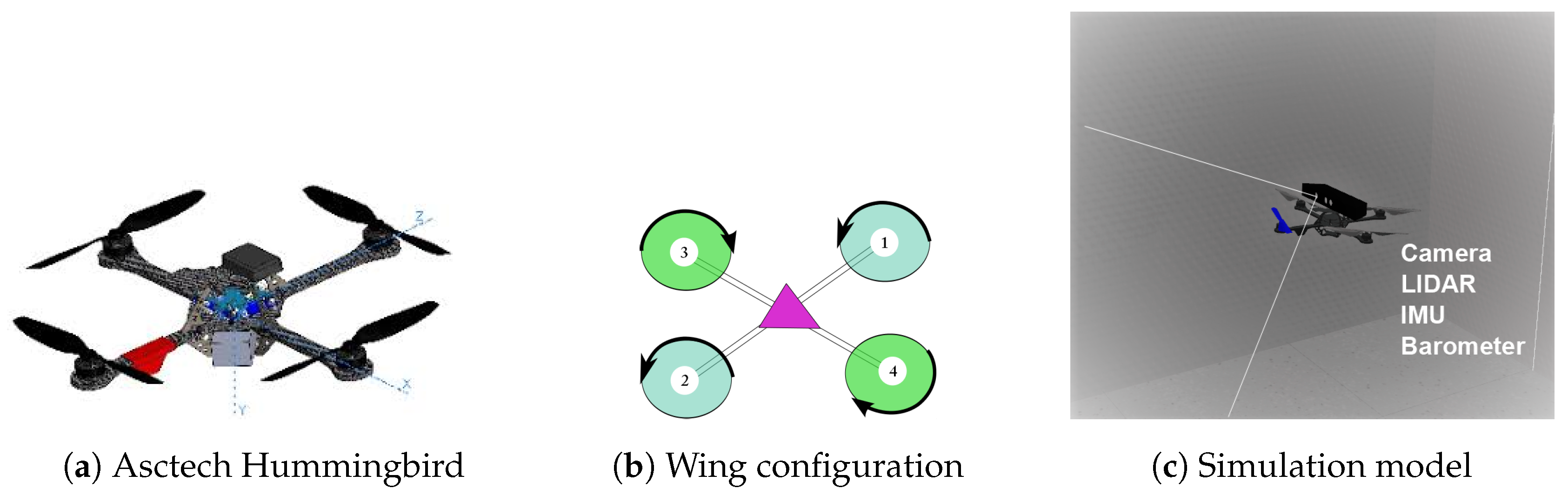
The simulation model is based on the Asctec Hummingbird multirotor (Figure 1a) and is equipped with an Inertial Measurement Unit (IMU) for a 9 DOF position estimate, barometer for altitude control, a Microsoft Kinect that doubles as an RGBD camera and a 2D Light Detection and Ranging LIDAR sensor . The wing configuration is as presented in Figure 1b, and shows the forward motion by the arrow. Through testing we found that this configuration provides better agility with the kinect sensor mounted on the top. The kinematics and dynamics of the UAV were adopted as described in [11].
2.1. Software
All simulations were performed on the Gazebo software. Gazebo comes with a physics engine that can imitate actual motions of different configurations of UAVs and makes it possible to test a UAS in different scenarios both indoors and outdoors [12]. It is also convenient for quickly testing algorithms, adding new sensors and fast prototyping design changes. For programming and control, we used ROS or robot operating system. ROS is a middleware for robotics providing a software framework for robot software development [13,14]. It provides a broad collection of libraries that provide functions to robots with a focus on manipulation, perception and mobility. It also provides various set of tools for debugging, testing and visualizing sensor data and tools for networking for multi-robot and distributed systems. Another reason for using ROS is due to its excellent integration with the Gazebo simulator.
2.2. Control and Estimation
An extended Kalman filter was used to fuse all the sensor data coming from the UAV into a single navigation information to control the velocity, orientation and position of the UAV along with sensor error bias. A set of Proportional Integration and Derivation (PID) controllers were implemented to control the attitude, yaw rate, and velocity of the vehicle along with heading. The output values that contain the thrust and torques are then translated into motor voltages that gives a response that is similar to the actual aerial vehicle. The open source ArduPilot was used as a flight controller to translate these messages into necessary motor voltages and is used to simulate and fly the vehicle [15]. The parameters for each element can be fine tuned to get a desirable response such as hovering at a place or complex maneuvers. Other techniques for path planning can be implemented in the control loop to obtain a smoother response from the UAV [16]. Such software in the loop approach provides greater flexibility in testing algorithms before actual implementation on a real platform and avoids the risk of damage or injury.
3. Methods
This section describes the mapping and exploration methods used for the experiments.
3.1. SLAM
To operate in an unknown environment with or without GPS signals, the UAV needs to implement SLAM to ascertain its position in the environment and gather sensor data that is used to build the map of the environment. For mapping we used the GMapping or grid mapping to create a 2D occupancy grid map from the LIDAR data and pose data from the UAV. The 2D grid map was also utilized for the frontier exploration which is explained later. The GMapping method uses a Rao-Blackwellized particle filter that re-samples each particle in an iterative manner, dropping the bad particles while ensuring that good particles remain. The mathematical details about the method can be found in [3]. A laser scan matching algorithm is employed that estimates the pose of the vehicle from consecutive laser scans. This ensures that sampling points are selected in an area around the current pose thereby reducing the number of particles required by the particle filter algorithm and making it computationally effective. As the UAV explores the environment, the grid map is updated continuously. The 3D pointcloud generated from the kinect sensor is also stored to reconstruct a dense 3D map of the environment.
3.2. Exploration
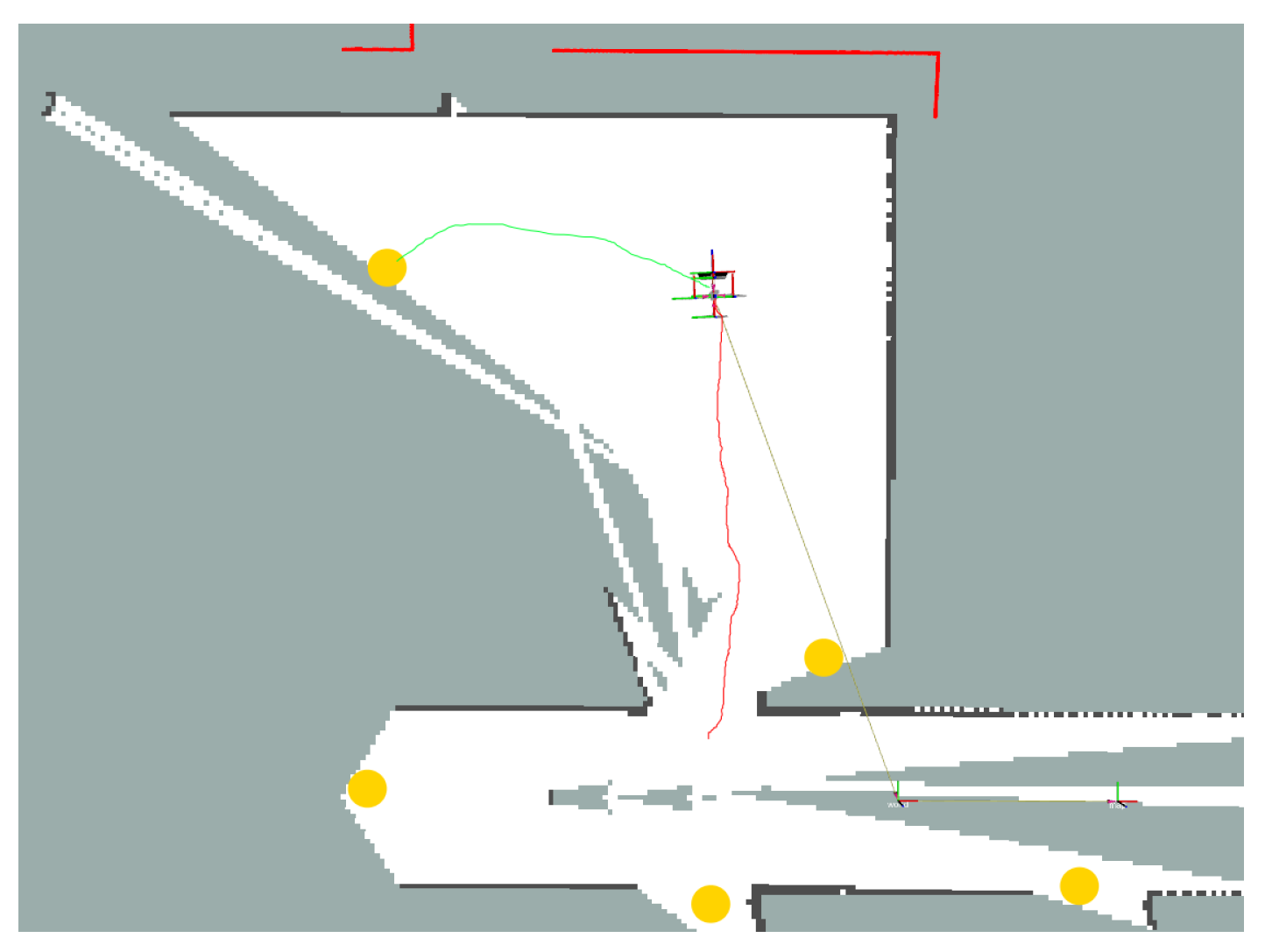
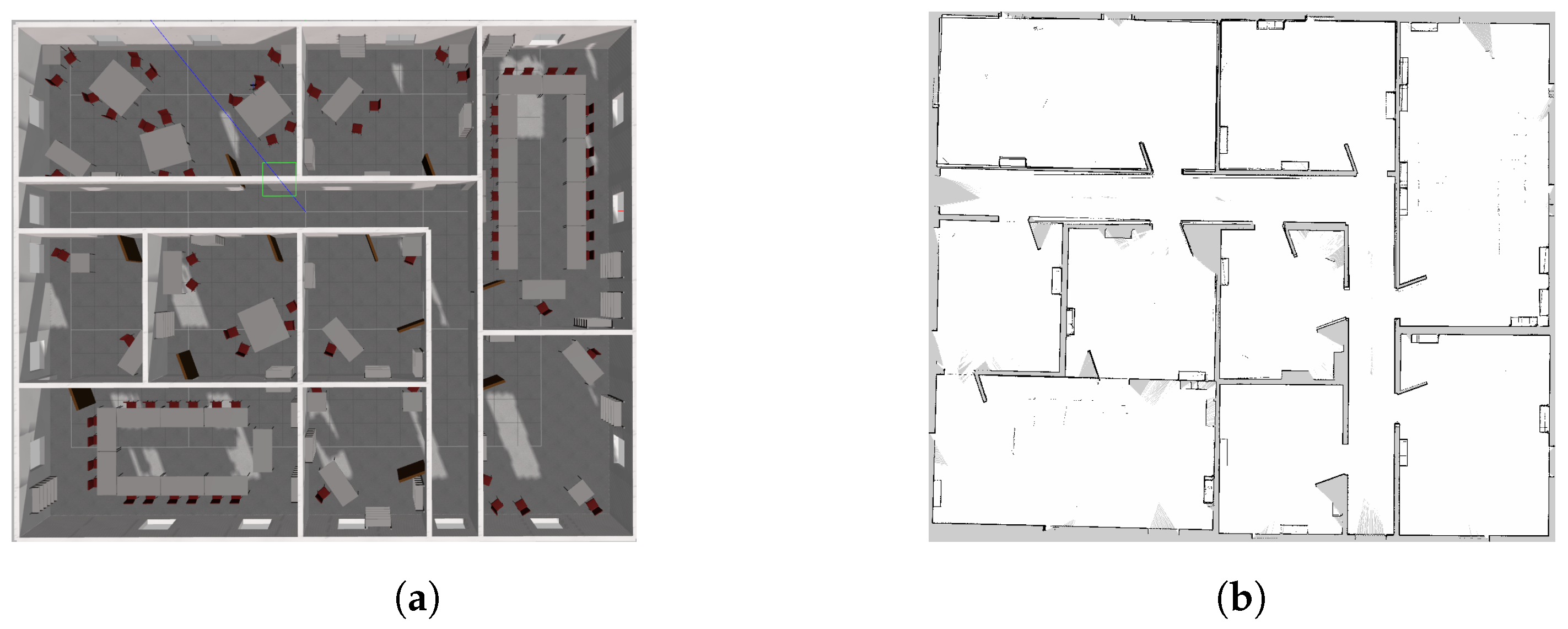
For autonomous exploration, we used the frontier exploration method. A frontier on the map is the boundary between explored and unexplored regions. The algorithm works on a simple principle where visiting such frontiers constantly increases new information about the area and pushes the boundary as more areas are explored [17]. The exploration algorithm aims at detecting, labeling and listing all the edges (cells) that are explored and unexplored as frontier regions. By calculating the minimum size threshold, it generates a list of suitable frontiers for the vehicle to navigate to from its current pose while ignoring smaller frontiers. The selection for the next best frontier to visit is based on different criteria, such as, distance to the frontier from the current pose, and the size of the frontier. As the UAV continuously explores the region the grip map is updated using the SLAM method and is utilized for autonomous navigation. Figure 2 shows the UAV exploration using the frontier algorithm. The yellow circles are the detected frontiers. The red trajectory is the UAV’s current trajectory, and the green trajectory shows the plan to selected next frontier. Figure 3 shows the gazebo model of the indoor scene. It has several rooms with similar looking features along with corridors and doors. The UAV was able to explore all the areas successfully using frontier exploration. Figure 3b, shows the final grid map obtained by the exploration method.
3.3. Navigation
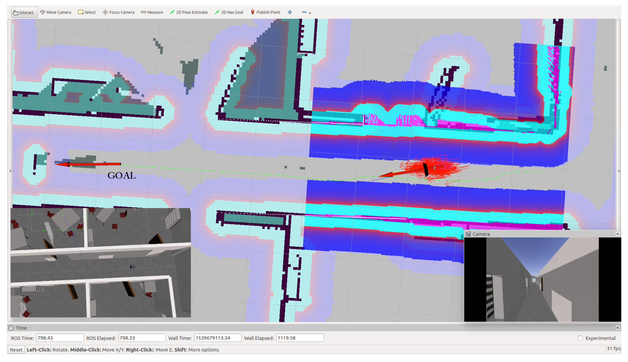
Once all the areas have been explored, autonomous navigation can be done using the obtained grid map. The navigation planner uses the global and local planner to autonomously navigate from one pose to another in the grid map. The global planner plans the path from the current pose to the goal pose using the A-star algorithm, while the local planner generates the linear and angular velocities along the global path while avoiding static or dynamic obstacles based on the cost map parameters. The local planner uses the dynamic window approach (DWA) planner to sample the velocities [18]. The exploration node only provides the goal pose (), and these are converted into NED (North-East-Down) frame. The poses are then translated into motor velocity commands to send to the flight controller which uses PID to navigate to the goal pose.
Figure 4.
Autonomous navigation using adaptive monte carlo localization (AMCL). The red arrows indicate particles. Goal is indicated by the red arrow. Cost map around the obstacles are shown in blue and cyan.
Figure 4.
Autonomous navigation using adaptive monte carlo localization (AMCL). The red arrows indicate particles. Goal is indicated by the red arrow. Cost map around the obstacles are shown in blue and cyan.

Prior to setting the goal and autonomous navigation, it is important to set the initial position of the UAV in the map. This is achieved by setting the initial pose of the UAV in the grid map. A scan matcher node then corresponds the laser scans with respect to the map, and corrects the position of the UAV [19]. Once the UAV has localized itself in the map, goal pose can be given for autonomous tasks. The localization is done using the adaptive Monte Carlo localization (AMCL) stack available on ROS. AMCL is a probabilistic technique to localize a moving robot system in the given map [3]. It uses the Monte Carlo localization approach wherein particle filters are used to track the pose of the robot against a known map [3,20]. The localization is done by matching the laser scan data at a given pose of the robot with the map. If at any given time, the autonomous navigation fails, a fail-safe system is implemented that commands the UAV to land. An emergency signal is sent to the control station and manual flight operation of the drone can be implemented using the live camera feed from the RGBD camera to retrieve the vehicle.
3.4. 3D Construction
The data gathered from the RGBD camera was used to generate a dense 3D map of the indoor environment. This is achieved by spatial alignment, where a series of images from same scene at different times are geometrically aligned with different sensors or different view-frames [21]. A loop closure detection method was employed that uses fast image matching technique by extracting robust features from the image (e.g., scale invariant feature transform (SIFT) or Speeded Up Robust Features (SURF) ). By matching previous local features to current images that belong to a similar scene we can ascertain if the robot has returned to a previously mapped region and close the loop. Figure 5a shows an example of feature matching using SIFT (scale invariant feature transform) features in subsequent images recorded by RGBD camera [22]. For 3D construction, the iterative closest point (ICP) method (3D variant) is used to match and stitch the 3D data obtained from the RGBD camera. The generated pointcloud is tranferred to OctoMap package in ROS that converts the pointcloud into a 3D occupancy grid map. OctoMap uses an octree data structure to recursively divide the pointcloud into an octree cell that is further classified into occupied or unoccupied cells [23]. An example of a generated 3D occupancy grid of the indoor map is shown in Figure 5b.
4. Conclusions
In this paper, we tested algorithms for autonomous mapping and exploration by a UAV in unknown indoor environments. A simulation model of the drone was developed in gazebo simulator and an indoor scene was constructed to test the proposed algorithms. Our aim of the research was to test whether mapping and exploration can be performed by using low-cost RGBD sensors as the only visual inertial sensor. A frontier exploration strategy was implemented to explore the indoor scene using LIDAR data generated from the RGBD sensor. By generating navigation goals using the frontiers, the UAV was able to explore the complete map. Furthermore, we implemented SLAM on the UAV to get accurate 2D grid map of the scene that was used for autonomous navigation. A 3D reconstruction method using OctoMap is presented that allows the creation of highly dense 3D maps of the environment that can be further used for 3D navigation. From the results we confirm that autonomous operation using only an RGBD camera is possible for the UAV system. For future work we plan to implement multi-drone system in simulation to reduce the time taken for mapping using the frontier exploration. Also, we plan to test the proposed framework on a real platform (UAS) for autonomous mapping and exploration.
Author Contributions
A.A.R. and A.R. conceived the idea, designed, performed experiments, and summarized the research; Y. K. made valuable suggestions to analyze the data and improve the manuscript. T. E. provided important feedback to improve the manuscript. The manuscript was written by A.A.R.
Conflicts of Interest
The authors declare no conflict of interest.
References
- Yamaguchi, S.P.; Sakuma, M.; Ueno, T.; Karolonek, F.; Uhl, T.; Ravankar, A.A.; Emaru, T.; Kobayashi, Y. Aerial Robot Model based design and verification of the single and multi-agent inspection application development. arXiv preprint arXiv:1812.05296 2018. [Google Scholar]
- Sakuma, M.; Kobayashi, Y.; Emaru, T.; Ravankar, A.A. Mapping of pier substructure using UAV. System Integration (SII), 2016 IEEE/SICE International Symposium on. IEEE, 2016, pp. 361–366.
- Thrun, S.; Burgard, W.; Fox, D. Probabilistic robotics; MIT Press: Cambridge, MA, USA, 2005. [Google Scholar]
- Kumar, V.; Michael, N. Opportunities and challenges with autonomous micro aerial vehicles. Int. J. Robot. Res. 2012, 31, 1279–1291. [Google Scholar] [CrossRef]
- Grzonka, S.; Grisetti, G.; Burgard, W. A fully autonomous indoor quadrotor. IEEE Trans. Robot. 2012, 28, 90–100. [Google Scholar] [CrossRef]
- Cadena, C.; Carlone, L.; Carrillo, H.; Latif, Y.; Scaramuzza, D.; Neira, J.; Reid, I.; Leonard, J.J. Past, present, and future of simultaneous localization and mapping: Toward the robust-perception age. IEEE Trans. Robot. 2016, 32, 1309–1332. [Google Scholar] [CrossRef]
- Ravankar, A.; Ravankar, A.A.; Kobayashi, Y.; Emaru, T. Symbiotic navigation in multi-robot systems with remote obstacle knowledge sharing. Sensors 2017, 17, 1581. [Google Scholar] [CrossRef] [PubMed]
- Ravankar, A.; Ravankar, A.A.; Kobayashi, Y.; Emaru, T. On a bio-inspired hybrid pheromone signalling for efficient map exploration of multiple mobile service robots. Artif. Life Robot. 2016, 21, 221–231. [Google Scholar] [CrossRef]
- Ravankar, A.; Ravankar, A.; Kobayashi, Y.; Hoshino, Y.; Peng, C.C.; Watanabe, M. Hitchhiking Based Symbiotic Multi-Robot Navigation in Sensor Networks. Robotics 2018, 7, 37. [Google Scholar] [CrossRef]
- Ravankar, A.; Ravankar, A.A.; Kobayashi, Y.; Emaru, T. Hitchhiking Robots: A Collaborative Approach for Efficient Multi-Robot Navigation in Indoor Environments. Sensors 2017, 17, 1878. [Google Scholar] [CrossRef] [PubMed]
- Meyer, J.; Sendobry, A.; Kohlbrecher, S.; Klingauf, U.; Von Stryk, O. Comprehensive simulation of quadrotor uavs using ros and gazebo. In Proceedings of the International conference on simulation, modeling, and programming for autonomous robots, Tsukuba, Japan, 5–8 November 2012; Springer: Berlin/Heidelberg, Germany, 2012; pp. 400–411. [Google Scholar]
- Gazebo Simulator Homepage. Available online: http://gazebosim.org/ (accessed on 1 September 2018).
- Quigley, M.; Conley, K.; Gerkey, B.; Faust, J.; Foote, T.; Leibs, J.; Wheeler, R.; Ng, A.Y. ROS: An open-source Robot Operating System. In Proceedings of the ICRA Workshop on Open Source Software, Kobe, Japan, 12 May 2009; Volume 3, p. 5. [Google Scholar]
- ROS: Robot Operating System Wiki. Available online: http://wiki.ros.org/ (accessed on 5 September 2018).
- ArduPilot: Open Source Autopilot. Available online: http://ardupilot.org/ (accessed on 12 October 2018).
- Ravankar, A.; Ravankar, A.; Kobayashi, Y.; Hoshino, Y.; Peng, C.C. Path Smoothing Techniques in Robot Navigation: State-of-the-Art, Current and Future Challenges. Sensors 2018, 18, 3170. [Google Scholar] [CrossRef] [PubMed]
- Yamauchi, B. A frontier-based approach for autonomous exploration. In Proceedings of the 1997 IEEE International Symposium on Computational Intelligence in Robotics and Automation, Monterey, CA, USA, 10–11 July 1997; pp. 146–151. [Google Scholar]
- Fox, D.; Burgard, W.; Thrun, S. The dynamic window approach to collision avoidance. IEEE Robot. Autom. Mag. 1997, 4, 23–33. [Google Scholar] [CrossRef]
- Ravankar, A.A.; Kobayashi, Y.; Emaru, T. Clustering based loop closure technique for 2d robot mapping based on ekf-slam. In Proceedings of the 7th Asia Modelling Symposium (AMS), Hong Kong, China, 23–25 July 2013; pp. 72–77. [Google Scholar]
- Fox, D.; Burgard, W.; Dellaert, F.; Thrun, S. Monte carlo localization: Efficient position estimation for mobile robots. AAAI/IAAI 1999, 1999, 2. [Google Scholar]
- Mitchell, H.B. Spatial Alignment. In Image Fusion: Theories, Techniques and Applications; Springer: Berlin/Heidelberg, Germany, 2010; pp. 35–51. [Google Scholar] [CrossRef]
- Lowe, D.G. Distinctive image features from scale-invariant keypoints. Int. J. Comput. Vis. 2004, 60, 91–110. [Google Scholar] [CrossRef]
- Hornung, A.; Wurm, K.M.; Bennewitz, M.; Stachniss, C.; Burgard, W. OctoMap: An efficient probabilistic 3D mapping framework based on octrees. Auton. Robots 2013, 34, 189–206. [Google Scholar] [CrossRef]
Figure 1.
Developed unmanned aerial vehicle (UAV) simulation model. (LIDAR),Inertial Measurement Unit (IMU).
Figure 1.
Developed unmanned aerial vehicle (UAV) simulation model. (LIDAR),Inertial Measurement Unit (IMU).

Figure 2.
Frontier exploration on the UAV. The yellow circles are the frontiers detected on the grid map.
Figure 2.
Frontier exploration on the UAV. The yellow circles are the frontiers detected on the grid map.

Figure 3.
(a) Gazebo environment and, (b) result of 2D grid mapping using UAV exploration

Figure 5.
(a) Loop closure detection using scale invariant feature transform (SIFT) features and (b) 3D reconstruction using OctoMap.
Figure 5.
(a) Loop closure detection using scale invariant feature transform (SIFT) features and (b) 3D reconstruction using OctoMap.

© 2018 by the authors. Licensee MDPI, Basel, Switzerland. This article is an open access article distributed under the terms and conditions of the Creative Commons Attribution (CC BY) license (https://creativecommons.org/licenses/by/4.0/).
Share and Cite
MDPI and ACS Style
Ravankar, A.A.; Ravankar, A.; Kobayashi, Y.; Emaru, T. Autonomous Mapping and Exploration with Unmanned Aerial Vehicles Using Low Cost Sensors. Proceedings 2019, 4, 44. https://doi.org/10.3390/ecsa-5-05753
AMA Style
Ravankar AA, Ravankar A, Kobayashi Y, Emaru T. Autonomous Mapping and Exploration with Unmanned Aerial Vehicles Using Low Cost Sensors. Proceedings. 2019; 4(1):44. https://doi.org/10.3390/ecsa-5-05753
Chicago/Turabian StyleRavankar, Ankit A., Abhijeet Ravankar, Yukinori Kobayashi, and Takanori Emaru. 2019. "Autonomous Mapping and Exploration with Unmanned Aerial Vehicles Using Low Cost Sensors" Proceedings 4, no. 1: 44. https://doi.org/10.3390/ecsa-5-05753