
Adopting a Conversion Design Approach to Maximize the Energy Density of Battery Packs in Electric Vehicles


1
Institute of Engineering Design, Technische Universität Braunschweig, Hermann-Blenk-Straße 42, 38108 Braunschweig, Germany
2
Department of Industrial Engineering, University of Salerno, via Giovanni Paolo II 132, 84084 Fisciano, Italy
*
Author to whom correspondence should be addressed.
†
Current address at: Institute of Machine Tools and Production Technology, Technische Universität Braunschweig, Langer Kamp 19B, 38106 Braunschweig, Germany.
Energies 2021, 14(7), 1939; https://doi.org/10.3390/en14071939
Submission received: 22 February 2021
/
Revised: 22 March 2021
/
Accepted: 29 March 2021
/
Published: 31 March 2021
Abstract
:Innovative vehicle concepts have been developed in the past years in the automotive sector, including alternative drive systems such as hybrid and battery electric vehicles, so as to meet the environmental targets and cope with the increasingly stringent emissions regulations. The preferred hybridizing technology is lithium-ion battery, thanks to its high energy density. The optimal integration of battery packs in the vehicle is a challenging task when designing e-mobility concepts. Therefore, this work proposes a conceptual design procedure aimed at optimizing the sizing of hybrid and battery electric vehicles. Particularly, the influence of the cell type, physical disposition and arrangement of the electrical devices is accounted for within a conversion design framework. The optimization is focused on the trade-off between the battery pack capacity and weight. After introducing the main features of electric traction systems and their challenges compared to conventional ones, the relevant design properties of electric vehicles are analyzed. A detailed strategy, encompassing the selection of battery format and technology, battery pack design and final assessment of the proposed set-up, is presented and implemented in an exemplary application, assuming an existing commercial vehicle as the reference starting layout. Prismatic, cylindrical and pouch cells are configured aiming at achieving installed battery energy as close as possible to the reference one, while meeting the original installation space constraint. The best resulting configuration, which also guarantees similar peak power performance of the reference battery-pack, allows reducing the mass of the storage system down to 70% of its starting value.
1. Introduction
The transportation sector accounts for a significant amount of global greenhouse gas emissions (GHG). The growth in world population during the last century has led to an increased demand for vehicles and a consequent increase in CO2 and NOx emissions. According to recent forecasts, the number of vehicles will increase to two and a half billion until 2050, contributing to a further degradation of environmental conditions [1]. Consequently, if this increasing amount is covered exclusively by traditional means of transport, equipped with common internal combustion engines, a huge demand for fuel will inevitably run out the primary resource reserves, already hardly tested by the massive exploitation that occurred in the last years. Action is needed now to avoid or at least reduce the concerning consequences of climate change.
In this context, the automotive industry has been pushed into a challenging transition, towards the development of combustion-free vehicles. Alternatives to conventional internal combustion engine vehicles, such as hybrid electric vehicles (HEV) and battery electric vehicles (BEV), have already been successfully introduced to the market or are currently receiving increasing attention, as is fuel cell vehicle technology [2]. In light of the increasing worldwide acceptance of electricity-powered vehicles, car manufacturers are intending to embark on the market for electric vehicles [3].
However, electric vehicles currently present higher prices than conventional vehicles and are not considered a mature technology yet. The most common trend is to underestimate EV performances and ranges [4] and overestimate the overall recharging cost, which could indeed benefit from adequate planning measures [5]. To overcome this widespread lack of knowledge, society’s perception shall be changed and EV performances and prices must become competitive compared to existing options. Hence, it is fundamental to promote these new technologies by providing more incentives to the best alternatives for electric transport [6].
Governments are boosting investments in research and development, particularly in the domain of traction batteries. Improvements in battery technology are indeed needed, concerning, for instance, their durability and efficiency in terms of energy density, safety issues, appropriate recycling and disposal practices, as well as design strategies for an effective vehicle integration. The technological development of storage systems in the electronics sector is necessary, so as to introduce vehicles in the automotive market that allow wider ranges, able to cover the individual daily average distance, provide better performance than traditional vehicles and, in parallel, considerably reduce the pollutant emissions [7,8]. The improvement of those crucial technical parameters, together with the promotion of renewable energy sources, could yield in the near future the long-awaited green revolution of the automotive sector [9].
Research work in the field of batteries for EV applications has mostly focused on the cell electrode materials, battery modelling methods to assess the battery state, health and safety and on integration of the charging infrastructure for EVs [10]. In BEVs and HEVs the integration of the battery pack is crucial in terms of vehicle dynamics and stability, as the battery pack is one of the heaviest components. The battery cell type and geometry as well as the disposition of the cells within the battery module can determine the total number of cells, their capacity and hence the overall range of the vehicle [11]. An optimal disposition of the battery cells according to the given restrictions is crucial to increase the energy density of the battery pack.
In the current research work, BEV and HEV configurations are examined and the optimal integration of energy storage systems is evaluated through a design methodology. This research work thus aims at the development of a conversion design procedure to optimize the integration of battery packs in commercial vehicles. The main purpose is to maximize the energy and power density of the selected battery, taking into account technical and geometrical constraints, by means of advanced conceptual design methodologies. The latter were indeed already proven effective both for electric vehicle light-weighting purposes [12], as well as to enhance the spreading of electrified aviation services [13].
2. State of Art and Research
2.1. Electric Vehicles
2.1.1. Classification and General Features
Electrification in the transportation sector is crucial to fulfil the targets of sustainable development. In the near future, electric vehicles will most likely dominate the vehicle market [14,15]. The spread of these propulsion systems was historically slowed down due to the technological inability to provide sufficient charge density to cover significant distances and provide performances in line with the ones required by the users. In the last years, the technological development of storage systems in the electronics sector has increased the attractiveness of electric vehicles [7].
Electric vehicles can be classified into battery electric vehicles (BEV), hybrid electric vehicles (HEV), plug-in hybrid electric vehicles (PHEV) and fuel cell electric vehicles (FCEV) [16]. This research work focuses on BEV and HEV systems.
Battery electric vehicles run fully electric and the combustion engine is replaced by a battery system with rechargeable batteries [17]. The energy storage system, i.e., the battery pack, is the most expensive and also the most crucial component, as the battery capacity determines the range of the vehicle. The main drawback of BEVs is currently the relatively limited range compared to conventional vehicles, due to technical and design constraints [11].
Hybrid electric vehicles combine the benefits of fuel-based engines and electric motors and can be configured in different ways [16,18]. In all hybrid electric vehicles, the internal combustion engine provides most of the required power, while the electric motor is powered by a storage system and is used as secondary source of power. HEV configurations are more complex than those of BEVs, as they include more components. HEVs are usually classified into series and parallel configurations.
2.1.2. Conversion and Purpose Design
The design procedure is the relevant step within the development process in the automotive sector, closely linked to the research and production areas that are focused on the coordination of vehicle dimensions, material concepts and production processes.
The design process of electrified vehicles is based on the same principles of conventional vehicles: optimal integration of the components, driving characteristics, fuel consumption, vehicle safety, ergonomics and design. As mentioned above, the battery pack is a relevant component in EVs and its integration needs to be optimized according to space limitations.
The methodology to design the battery pack is usually based on the optimization of electrode materials, state of health, assembly, thermal behavior, mechanical safety and recycling [19], as described in more detail in the following section. Most of the studies available in the literature focus on one of those aspects. For an efficient design of the battery pack, it is important to consider different influencing factors. In [19], a comprehensive design methodology for battery packs has been proposed, incorporating multidisciplinary aspects: production, assembly, operation and recycling.
Hence, recent research has been seeking for an optimization of the battery packs. This work aims instead at investigating an optimal integration of the battery pack in existing commercial vehicles, taking into account space constraints and vehicle performance in terms of capacity.
Currently, car manufacturers are adopting two different concepts in the developing phase of electric vehicles: conversion and purpose design [20].
Conversion design consists of the integration of the high-voltage components into the existing on-board infrastructure of a commercial vehicle model developed for conventional engines and the adaptation to the new target use. Using this approach, relatively low investment costs are required, as the body, interior and chassis of the conventional series model are retained [21]. Nevertheless, the overall production costs of an electric vehicle are significantly higher than a vehicle with a conventional driving system, as the production process and assembly steps need to be adapted to the new product requirements [20]. In the presented methodology, a conversion design approach is chosen.
In order to enhance the competitiveness of electric vehicles, new design concepts need to be introduced. Purpose-oriented design involves the development of a new vehicle model, with a new arrangement of the components, to meet the requirements of an electric vehicle [9]. Through purpose-oriented design approaches, a long-term reduction of the production costs can be achieved [20].
Both for conversion and purpose-oriented concepts, in the design phase, rearrangements are required to allocate the battery pack in a crash-safe location and to ensure space optimization as well as an appropriate weight distribution along the vehicle [22]. Prediction models, engineering design methodologies and simulation tools can be used to support the development of electric vehicles, taking into account relevant influencing factors (e.g., safety, vehicle dynamics) and components (battery, power electronics, motor, gear) [23].
2.2. Battery Technology
The most common rechargeable batteries available on the market, with potential use on EVs, are lead acid (Pb), nickel-cadmium (NiCd), nickel-metal hybride (NiMH) and lithium-ion batteries (LIB). Lithium-ion batteries are currently among the most promising technologies used in the automotive field. Lithium-ion batteries have the highest gravimetric energy and density, compared to the other commercial typologies.
2.2.1. Cell Geometries
Three main battery geometries are currently available in the market and can be employed for automotive applications: cylindrical (hard-case), pouch (soft-pack), and prismatic (hard-case). Apart from their shape, these cell types differ for the inner structure, the manufacturing process and the cell unit assembly, including the cutting process, the compound assembly and the final packaging [24]. During the EV design process, several factors influence the choice of the cell geometry.
The cylindrical cell is the most common technology for primary and secondary batteries. Besides being easy to manufacture, cylindrical cells are characterized by good mechanical stability and safety properties. The watt-per-hour cost is relatively low, due to their long life-time [25]. The drawbacks are the low packaging density and the lower heat transport. Space efficiency in the battery pack assembly is more challenging compared to other formats [26].
The prismatic cell is characterized by a thin profile, lightness and space efficiency. In fact, its rectangular shape and thinness facilitate layering and give product designers increased flexibility. Nevertheless, they are more expensive than cylindrical cells to design and manufacture, thus becoming expensive for consumers too. In addition, there is a limited number of standardized sizes in the market compared to cylindrical cells.
The pouch cell is a lightweight alternative of battery design. Conductive foils are welded around the electrodes and sealed in a so-called pouch bag [27]. Therefore, the metal enclosure is eliminated and the space can be used more efficiently, resulting in an overall reduced weight. However, a great disadvantage is the swelling that can occur due to gassing. It is therefore recommended not to stack pouch cells vertically, but rather to lay them side by side [28].
Cylindrical and prismatic cells present better safety performance properties than pouch cells because of their hard cases and the presence of a pressure valve. They are therefore considered more reliable. Nevertheless, cylindrical and prismatic cell housings add additional weight to the cell, leading to a reduced energy density. Pouch cells might be a promising solution for the automotive industry, due to the described properties [24].
2.2.2. Requirements for Automotive Applications
The integration of the energy storage system into the vehicle represents a challenging task for car designers and manufacturers. The storage system must indeed meet several requirements, which can be categorized into five main classes: energy, cost, mechanics, environment and safety (see Table 1).
2.3. Design Variables and Specifications
An appropriate selection of the battery typology and geometry is crucial to achieve a good performance in terms of capacity, while keeping the overall weight of the battery pack as low as possible. The selection of the battery pack location is also a key variable in the design phase, to guarantee the vehicle stability through a correct weight distribution, while optimizing the available space.
When considering an upscale of the design methodology, the optimal size of a battery pack can be determined in relation to the overall fleet performance, as presented in [38].
2.3.1. Relevant Battery Operational Parameters
Batteries are rated with a defined voltage and capacity. The battery rated voltage is the nominal operational voltage, while the capacity, measured in Ah, is the charge that a battery can supply at a rated voltage. The energy capacity in watt-hours (Wh) is proportional to the amount of electrode material in the battery.
Another important parameter of a battery is the energy density, mostly used to compare battery systems. It can be related either to the weight of the battery (gravimetric energy density or specific energy), or to the volume (volumetric energy density in Wh/dm3—or Wh/litre). The higher the density, the lower the weight, when comparing batteries with similar capacities [39,40].
The power density of a battery is defined as the maximum available power per unit volume, in W/dm3 or W/liter while, if compared to the unit mass, it is called specific power and is expressed in W/kg. The power density and specific power are a characteristic of the battery type and packaging and are crucial in the dimensioning process. However, a high energy density does not necessarily mean a high power density. A high power density involves as an output of the system large amounts of energy based on its volume, thus ensuring high driving performance. On the other hand, if a system has a high energy density, it is able to store more energy in a small amount of volume and increases the storage capacity in the system with the same mass.
Another relevant battery parameter is the so-called C-rate, the discharge rate of the battery, influenced by charging and discharging current.
Batteries are also characterized by the state of charge (SOC), the amount of stored residual energy, normalized with its total capacity.
The depth of discharge (DOD), is the amount of the battery capacity that has been discharged. Specifically, it is the amount of capacity in the battery that is usable by the system for powering the vehicle.
For automotive applications, batteries are connected into modules and packs. In those conditions, charge–discharge cycles may cause degradation of the battery module or pack, due to charge imbalances and different thermal characteristics. In order to reduce the impact of those external factors on the battery life-time, battery equalizers (e.g., cell-to-cell equalizers) can be integrated [41].
The battery efficiency (also called columbic efficiency) is the ratio of the number of charges that enter the battery during charging, compared to the number that can be extracted from the battery during discharging. In general, it can be defined as the ratio of the total storage system input to the total storage system output. The losses that reduce columbic efficiency are primarily due to the loss in charge due to secondary reactions such as the electrolysis of water or other redox reactions in the battery.
2.3.2. Battery Pack Weight
Batteries are among the heaviest components in EVs and can strongly influence automobile performances and affect vehicle stability through their improper placement into the vehicle.
The weight distribution influences the positioning of the center of gravity of the vehicle and hence its drivability [42,43]. A low center of gravity influences the dynamics and performance positively: the lower the center of gravity, the better the dynamic behaviour of the car [44].
It is important to remark that the battery pack weight does not change depending on the battery’s charge level (i.e., whether it is fully charged or fully discharged) while in ICE vehicles the overall vehicle weight is affected by the fuel level.
Vehicle weight also affects fuel consumption: the heavier the vehicle, the higher the energy required [45]. Hence, the vehicle weight, closely linked to its size, is a decisive factor for determining the energy consumption. An increase in HEV weight would have a negative influence on the fuel consumption, thus the choice of the battery typology is of major importance.
In the case of BEVs, fuel consumption does not represent a parameter that could be penalized by the vehicle weight because they are equipped with electric motors instead of internal combustion engines. However, the weight of the battery has an impact on the acceleration of the vehicle [46].
2.3.3. Battery Pack Location
As mentioned above, the choice of the optimal location for the battery pack is crucial and must take into account various factors that could affect vehicle dynamics, stability and safety. The variety of typologies and formats of battery cells offer a relatively high flexibility for the choice of the battery pack location. However, some critical considerations about the vehicle stability and safety should be made before choosing the final location, in order to ensure the best performance parameters and guarantee passengers protection in the event of car accidents and heavy shocks during their driving cycles. The safety and protection of the ESS is a strong requirement for batteries integration inside EVs, as already discussed, because the deformation of batteries can lead to hazardous effects [49].
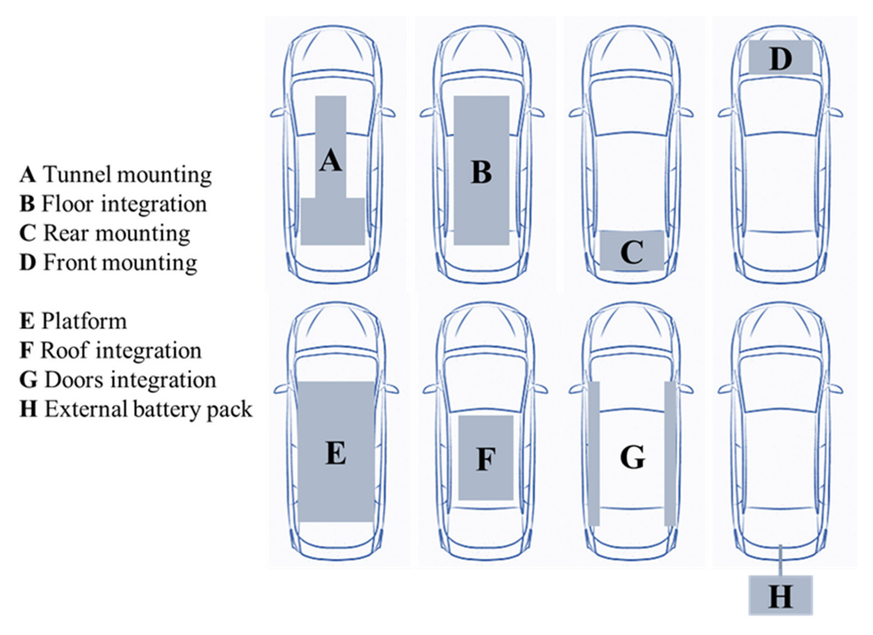
By analyzing and scanning all the existing EV models on the automotive market, it is possible to evaluate different battery pack installations and, due to safety and available space considerations, explore new possible ideas for their integration within the structure of EVs. The most viable locations for the battery pack are shown in Figure 1 and analyzed below in detail.
In the tunnel mounting, a T-shaped battery unit is mounted under the rear seats, keeping the center of gravity low. The T-shape centers the battery system in the car and the battery pack is in a more protected area in case of intrusion and collision. However, the interior floor area is reduced, affecting the coefficient of drag and the aerodynamic performance [50]. Commercially available car models are currently using this architecture, such as the Chevrolet Volt and the EV1.
The floor integration consists of integrating the battery pack under the occupants as a removable component, using all available space under the seats. This configuration provides an optimal weight distribution and a low center of gravity. Nevertheless, the battery could be exposed to impact conditions, leading to leakage or short-circuiting [51,52]. The models Mercedes B-Class Electric drive, Smart ED, Nissan Leaf and Toyota RAV4 EV follow this configuration. This configuration is used as benchmark in the proposed use-case.
The rear mounting is another possible arrangement, consisting of locating the battery pack in the rear part of the vehicle, under the back seat area. This location does not reduce the vehicle space available for occupants but it makes the battery pack vulnerable in a rear impact. The Toyota Prius PHEV was designed in this configuration.
The vehicle front area is usually occupied by most of the vehicle components, limiting the available space for additional components. Hence, the front mounting is not commonly used in conversion design strategies. In addition, this solution would lead to a bad weight distribution along the vehicle and a significant shift of the center of gravity. On the other hand, in the case of crash and fire, this location would be easier to access to extinguish a fire.
The platform configuration can be used in purpose design strategies, such as the Tesla S Model. In contrast to the floor-integrated packaging, the battery pack is not removable and does not require an additional protective structure. This battery system configuration allows an optimal weight distribution around the vehicle body. Nevertheless, if batteries are placed out of the vehicle perimeter, side impacts could be dangerous.
Roof integration has not been employed so far by any EV manufacturer; however, a critical analysis is worthy. Some bus models are in fact equipped with roof-integrated battery packs [53]. Of course, the design requirements of a car differ from those of a bus and the integration on a car’s roof would change the overall car geometry, shift the center of gravity to the upper part of the vehicle and consequently result in poor aerodynamic and drivability performance. Besides, the battery pack would require an additional casing to protect the system from the external weather conditions.
The door integration would embed battery cells in the body panels, thus exploiting an additional space otherwise unused and distributing in an optimal way the ESS weight between both sides of the vehicle. On the other hand, this configuration obviously adds complexity to the vehicle structure and manufacture. The weight penalty could be offset by the use of lighter materials, such as carbon fiber, and by installing very thin pouch cells, although aging may be a concern. Safety might also be an issue because even a minor parking mishap where a door gets dented could result in a lower operating mode of the battery pack or in serious damages. Moreover, battery access for testing, cleaning and the possible replacement of cells would not be so easy.
Finally, there could be the possibility of adding an external battery pack towed from the vehicle. This way, the design complexity would be reduced from a structural point of view because the battery pack would not be located inside the architecture and among the existing components; nevertheless, other problematic issues would appear. In fact, since the battery pack would be an external element, not included in the vehicle chassis, it would be subjected to mechanical shocks and vibrations from outside and thermal stress because of the different weather conditions. Hence, a protection casing and an appropriate heating/cooling system would be needed, considering that the wiring system would be more complex and more expensive. Additionally, the installation of a further heavy component in the rear area of the car would affect the vehicle stability both because it influences the center of gravity of the vehicle and makes the driving harder, even in the case of an easy and simple parking maneuver.
After this analysis, it is easy to understand how much wider the range of options is that the automotive designers have when the final battery pack installation and/or integration shall be chosen (see Figure 1). Different areas within the vehicle may be theoretically used, but the geometry is not the unique factor that drives to the best choice. Vehicle stability and passenger safety shall be adequately investigated, so as to ensure the vehicles the best performances and, at the same time, to guarantee to the passengers the expected protection in the event of car accidents and heavy shocks during each drive. Hence, the outcome of choosing the best battery pack location, between the ones described above, results in a vehicle with a proper center of gravity and a high crash safety performance. In this way, EVs can achieve dynamic stability and safety.
3. Methodological Approach
A well-designed battery pack system is essential to ensure high-performing operation of electric vehicles. Indeed, the vehicle performance parameters are affected by various factors deriving from the pack design, including the size of modules and cells, together with the arrangement of the cells in the delimited space and their technical specifications, such as rated capacity, nominal voltage, weight, etc.
Design methodologies are developed to identify optimal battery pack designs, taking into account a range of requirements, including velocity, acceleration, capacity, weight and safety.
The design methodology presented in this paper aims at simultaneously optimizing two vehicle parameters: the battery pack weight and capacity. Some of the most critical control factors to be considered in the pack design approach are the battery cell type, geometry, size, number of cells, location and space between cells and modules.
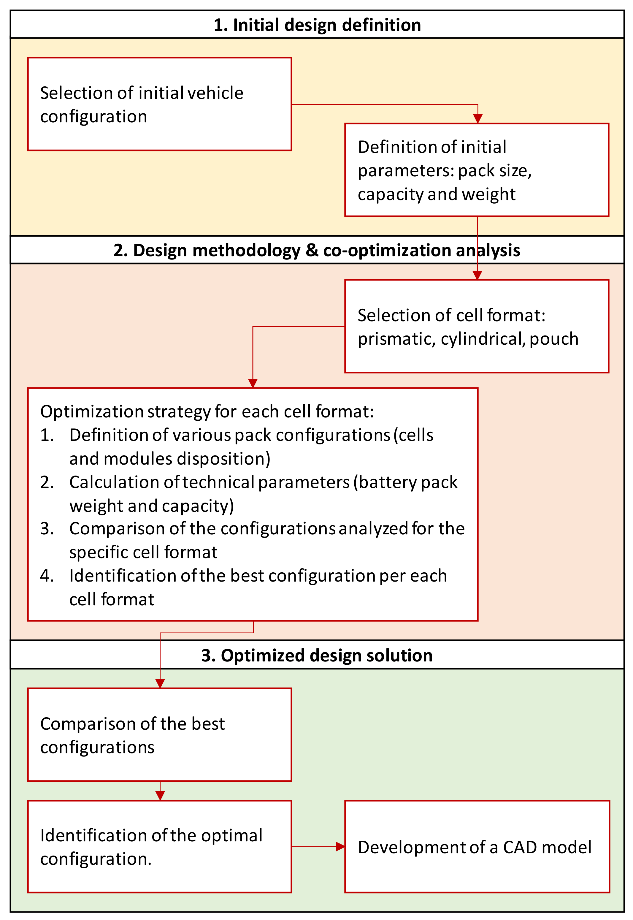
As depicted in Figure 2, the proposed methodology consists of three main phases.
In the first phase, the initial vehicle configuration is selected, in order to define the dimensions of the existing electrical components, i.e., cells, modules and the overall battery pack. This stage is crucial for the conversion design approach, as it allows to define the reference architecture, based on the chosen commercial vehicle, and the related restrictions.
The obtained reference is qualitative, compared to the chosen vehicle, because various assumptions have to be made in this stage. Battery management system and cooling are, for instance, neglected in the methodology. The main technical parameters are calculated as follows:
where n is the number of cells per module and m is the number of modules in the pack. C is the rated capacity and V is the nominal voltage of the single cell, whereas M is its mass.
In this way, the overall utilizable space is quantified, as well as the initial pack capacity and weight, and new design solutions can be developed.
In the second phase, various geometry and topology considerations are considered for assembling the overall battery pack in the available space, aiming at an optimization of the capacity and weight of the selected reference vehicle, as calculated in the previous step. Three specific cell formats are used in the analysis (i.e., prismatic, cylindrical, pouch) and various battery pack configurations are investigated for each cell typology. A screening of commercially available cells is made, based on their technical specifications.
Specific optimization strategies for each cell format are developed, taking into account both cells arrangement in modules and the module disposition in the battery pack. A rectangular case is assumed as the geometry of the module. The overall battery pack weight and capacity are calculated for each proposed configuration. A discussion about the different proposed design configurations investigated in each strategy is made so as to identify the format solution and relative configuration that provide better results in terms of the capacity and weight in comparison to the original vehicle scheme.
In the third phase, the best configurations, identified for each cell format in the previous step, are compared and the final optimal configuration of the cell dispositions within the module and the battery pack is determined. A CAD model of the optimal configuration is developed, providing a detailed graphical view of the optimized design, e.g., the configuration that provides an optimal minimization of mass and maximization of the energy capacity.
4. Results
4.1. Reference Vehicle and Battery Cells
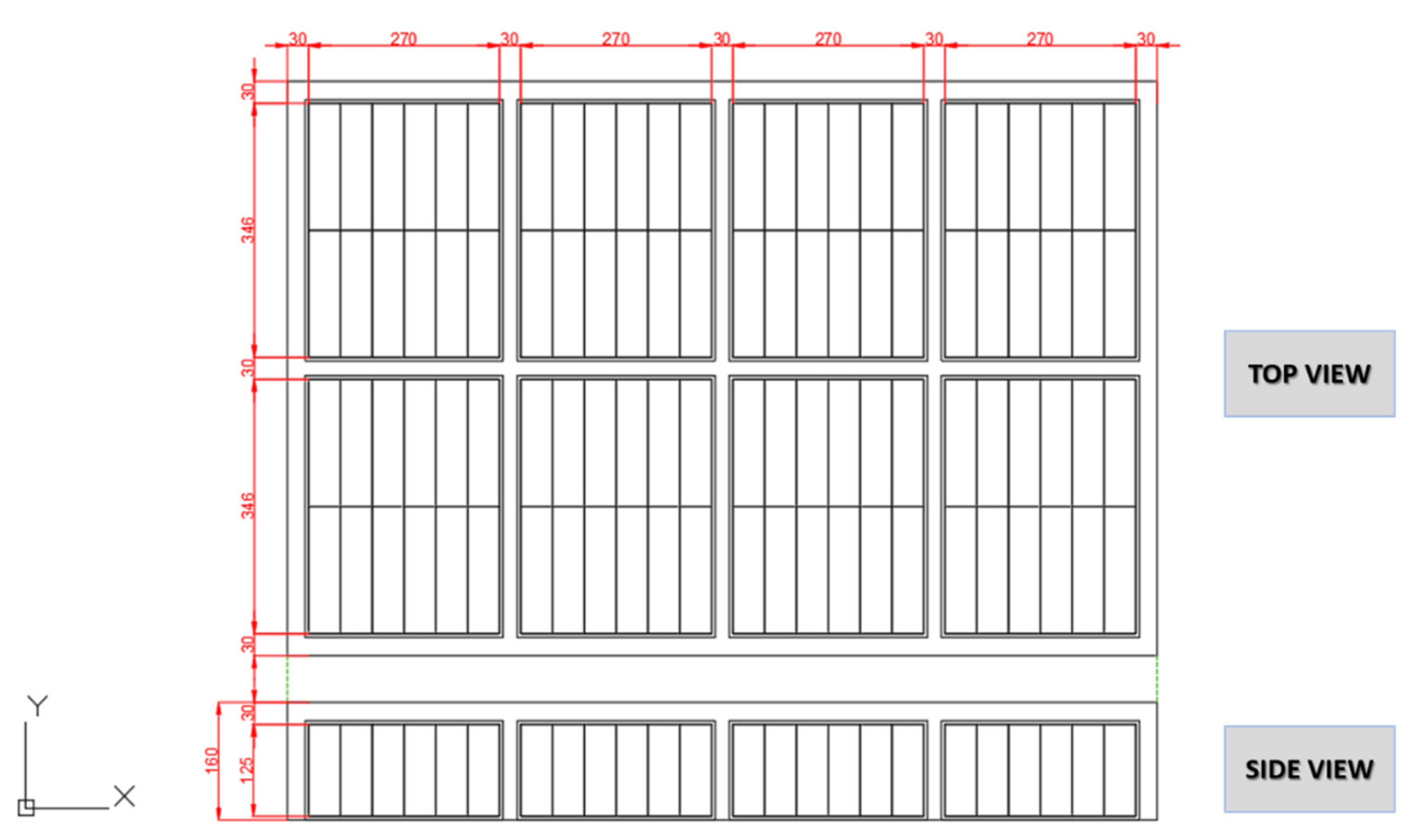
A conversion design approach is followed; i.e., a commercial electric vehicle concept (BMWi3 (https://www.press.bmwgroup.com/global/article/detail/T0259598EN/technical-specifications-for-the-bmw-i3-94ah-valid-from-07/2016?language=en, accessed on 31 March 2021) is used as a reference and modified with the final aim of optimizing its battery pack configuration. The BMWi3 model has been used as a reference in other studies, e.g., for powertrain modelling [54].
The BMWi3 was designed with floor battery integration architecture, equipped with 96 prismatic cells, manufactured by Samsung SDI (https://www.samsungsdi.com/automotive-battery/products/prismatic-lithium-ion-battery-cell.html, accessed on 31 March 2021). The high-voltage battery system (HVBS) consists of eight rectangular modules, arranged in four rows of two elements along the drive axle, each containing 12 cells connected in series.
Table 2 provides an overview of the technical specifications for the reference battery cells.
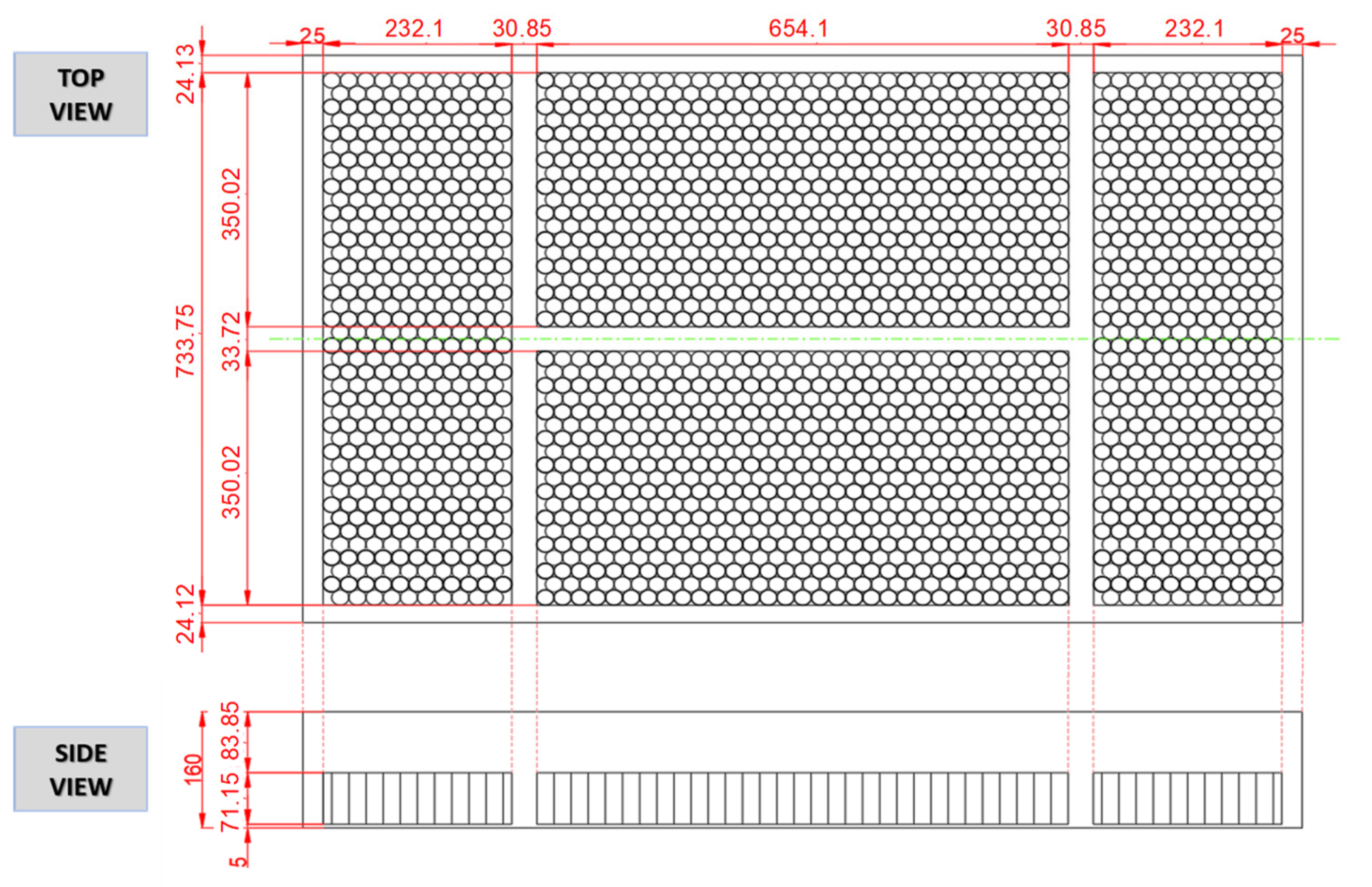
Figure 3 shows the original scheme of the BMWi3 battery pack, reporting the top and side view, detailing cells and modules disposal and all the geometrical measurements.
As mentioned above, some assumptions are made to reproduce the ESS structure of the chosen reference vehicle:
- Modules dimensions are calculated on the basis of the geometrical size of the cell typology used in the reference vehicle. Samsung SDI 94 Ah cells are arranged, side by side, in two rows of six elements per each module, thus obtaining 12 cells per module. Particularly, the length and width of modules are multiple of both sides of the prismatic cell installed;
- A width of 5 mm is assumed for the module casings;
- The distance between modules, without casing, and from modules to the pack boundary is assumed to be equal to 30 mm. However, the design procedure will be conducted assuring and maintaining at least 1.5 cm between module casings because all the electrical connections between modules always need to be guaranteed;
- No mechanical structure to hold and manage the cells arranged inside the modules are considered in the design methodology. All the electrical components are simply disposed next to each other;
- The reference battery pack is manufactured with rectangular models. This shape is retained also for the design methodology and, therefore, only rectangular cases are considered in the analysis;
- In the developed design analysis, neither the battery management system (BMS) nor the cooling systems are considered;
- Only the weight of the cells is considered in the calculation phases; e.g., the external cases of modules do not affect the overall weight evaluation.
The presence of the frame structure necessary for the installation of the batteries as well as the cooling and thermal systems would further reduce the available installation space. The optimization procedure is therefore not based on the real dimensions of BMWi3 battery pack but rather on a qualitative configuration. Furthermore, since this electric vehicle model is assumed as a basis for the implementation of the proposed design procedure, the methodology refers exclusively to the integration of batteries mounted in the lower part of the vehicle, i.e., floor integration (configuration B). During this study, the geometry of installation space within the body of the reference vehicle under examination was kept as fixed and was used to develop new and optimized battery pack configurations.
Considering the technical specifications of the Samsung SDI 94 Ah cells, it is possible to calculate the number of cells, the capacity and the weight of the BMWi3 battery pack:
These parameters resulting from (4–6) are the initial variables taken as basis for the optimization strategy.
4.2. Selected Configurations
The available volume for the installation of the HVBS within the body of the vehicle under examination has to be properly filled by placing and arranging cells and modules in the most suitable way. The objective is to correctly balance the weight on the whole floor of the electric vehicle and, at the same time, limit and minimize the space between the cells inside each module and between modules in the pack. The greater the number of cells that can be placed in each single module, the greater the amount of cells that the pack can host. As a result, the capacity of the converted battery pack will be higher. On the other hand, increasing the number of cells will definitely increase the overall weight of the battery pack. Therefore, it is essential to change the number and disposition of cells for the co-optimization of these two parameters: battery pack capacity and weight.
It is well-known that different design configurations are possible because of the great variety of cells formats and all the conceivable cells and modules dispositions.
Different configurations (see Table 3) were developed and thoroughly analyzed. Prismatic, cylindrical and pouch-cell formats were considered, and commercially available battery cells were used as reference.
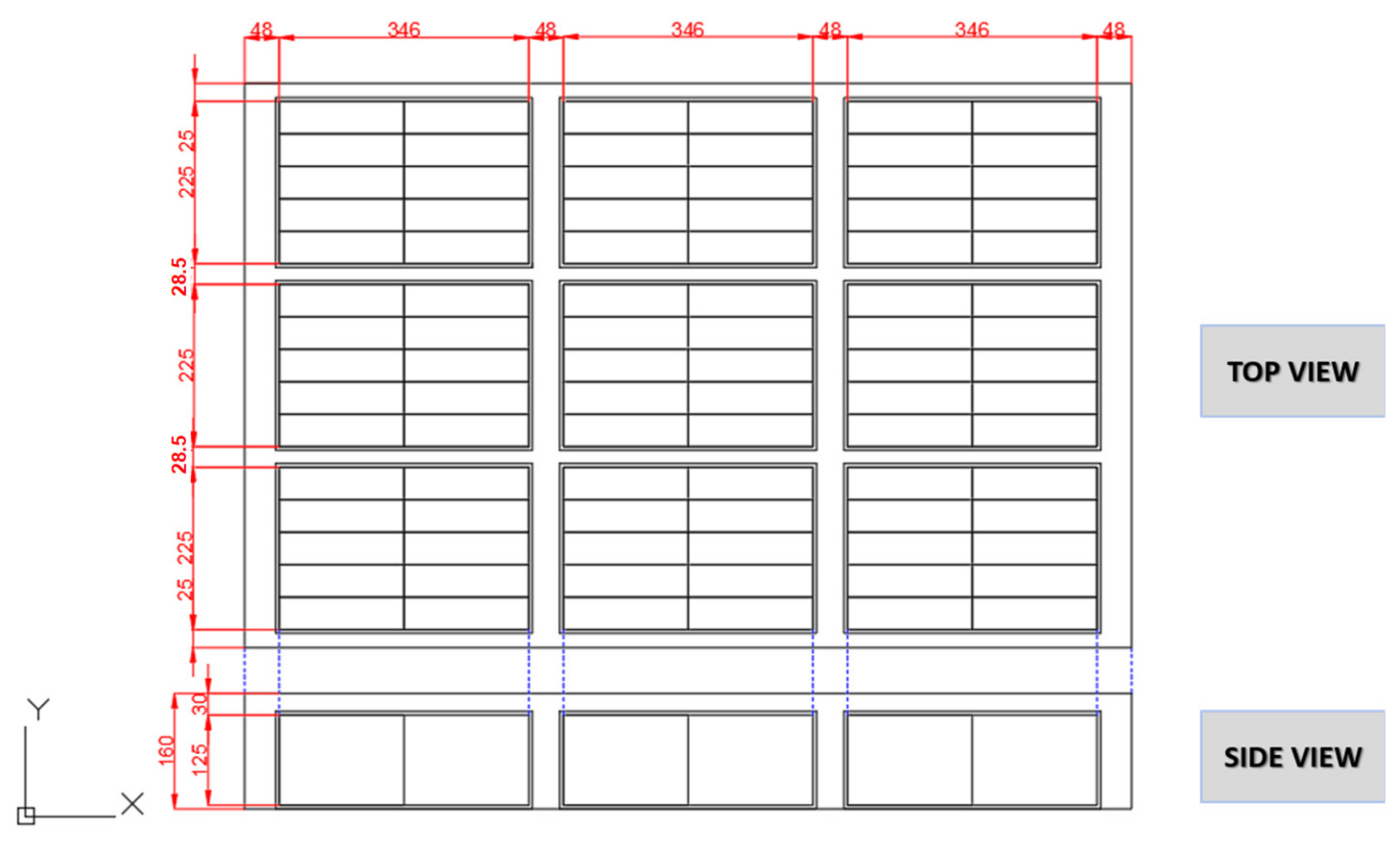
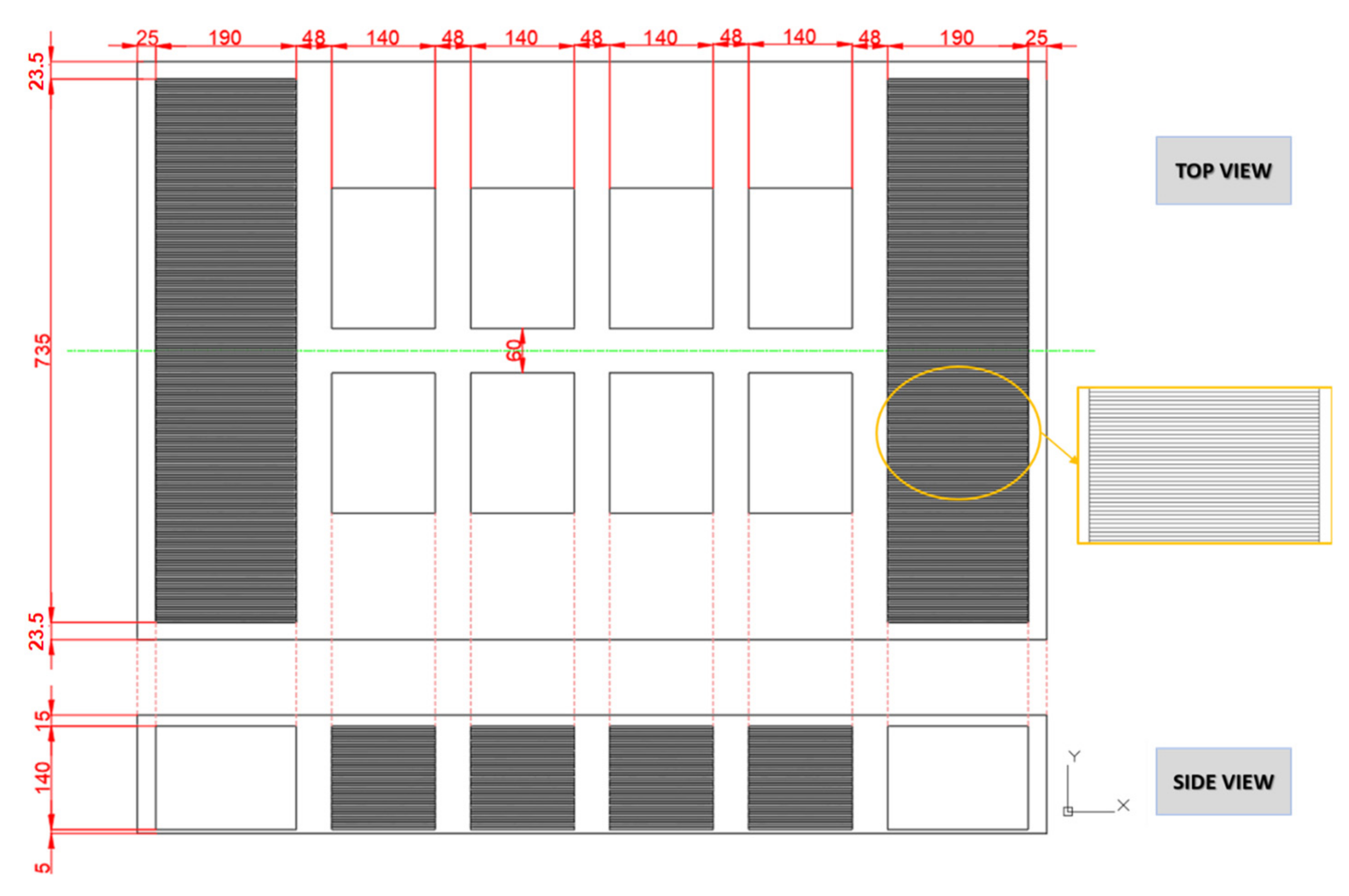
Configuration 1 involves the same cells installed in the reference vehicle but oriented differently, i.e., rotated 90°. The cell is arranged vertically, with the longer side parallel to the y-axis of the reference system, as shown in Figure 4. Based on the geometrical assumptions and the minimum distances to be respected, a disposition of 90 cells stacked in nine modules is obtained. Considering the new cell arrangement, six of the 96 cells originally installed in the reference BMWi3 pack are not included in the new configuration and, as a consequence, a slight weight reduction is expected.
Configuration 2, 3 and 4 were developed using a cell manufactured by Toshiba, with a lower average energy density but smaller size and weight than the cells used by the manufacturer. The aim was to investigate not only the effects that a different prismatic cell has on energy and capacity performances of the pack, but also its impact on the battery in terms of overall weight and layout. In both configuration 2 and configuration 3, the same dimensions of the modules are assumed, arranged as in the initial pack configuration under analysis.
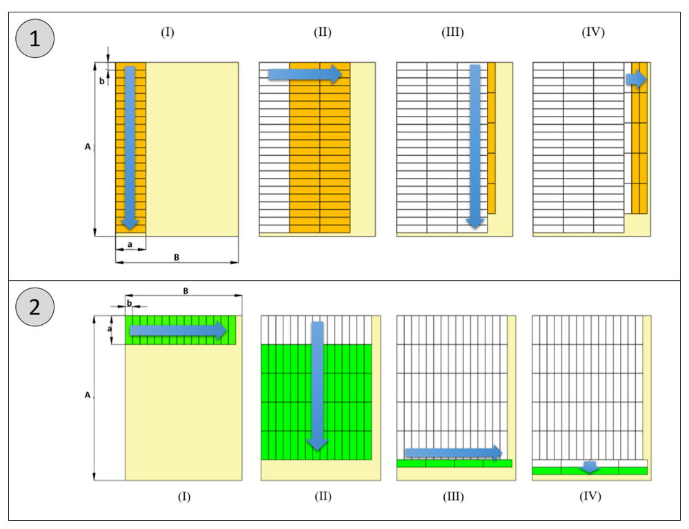
Two algorithms were developed and applied for configuration 2 and 3, respectively (see Figure 5):
- Algorithm 1 consists of first filling the longest side (A) of the module space with the shorter side (b) of the cell (I). This operation is repeated along the shorter side (B) of the installation space until no battery cell with its long side (a) entirely fits the space (II). After this first packaging phase, the remaining volume needs to be filled. In the second phase, the battery cells are rotated 90° and disposed along the entire long side (A) of the installation space (III). This operation is repeated until no further cell can be added in the remaining space (IV).
- Algorithm 2 consists of first filling the shorter side (B) of the installation space with the shorter side (b) of the battery cell (I) along the longest side (A) of the space (II). The remaining space is then filled, during the second packaging phase, along the shorter side (B), after a 90° rotation around the vertical axis of the battery cells (III). This operation is repeated along the longest side (A) until the remaining space is filled up.
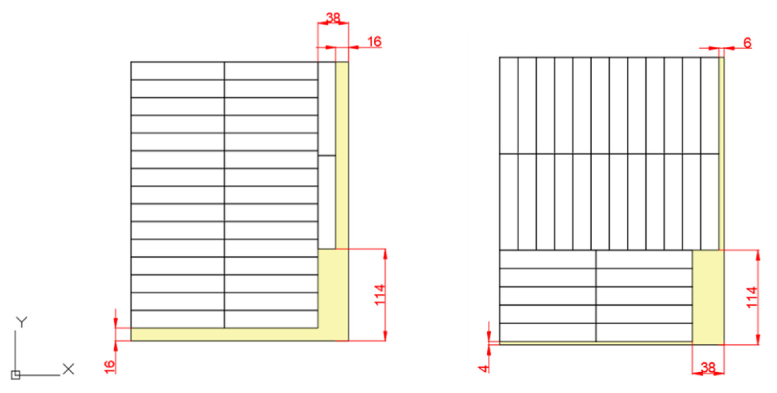
Following the steps of algorithm 1, it is possible to install in the available volume 32 cells per module, resulting in 256 cells for the overall pack. Out of the approach with algorithm 2, instead, the number of cells that can be inserted is furtherly increased to 272. Figure 6 shows in detail the single module with the Toshiba SCiB cells arrangement in both configurations.
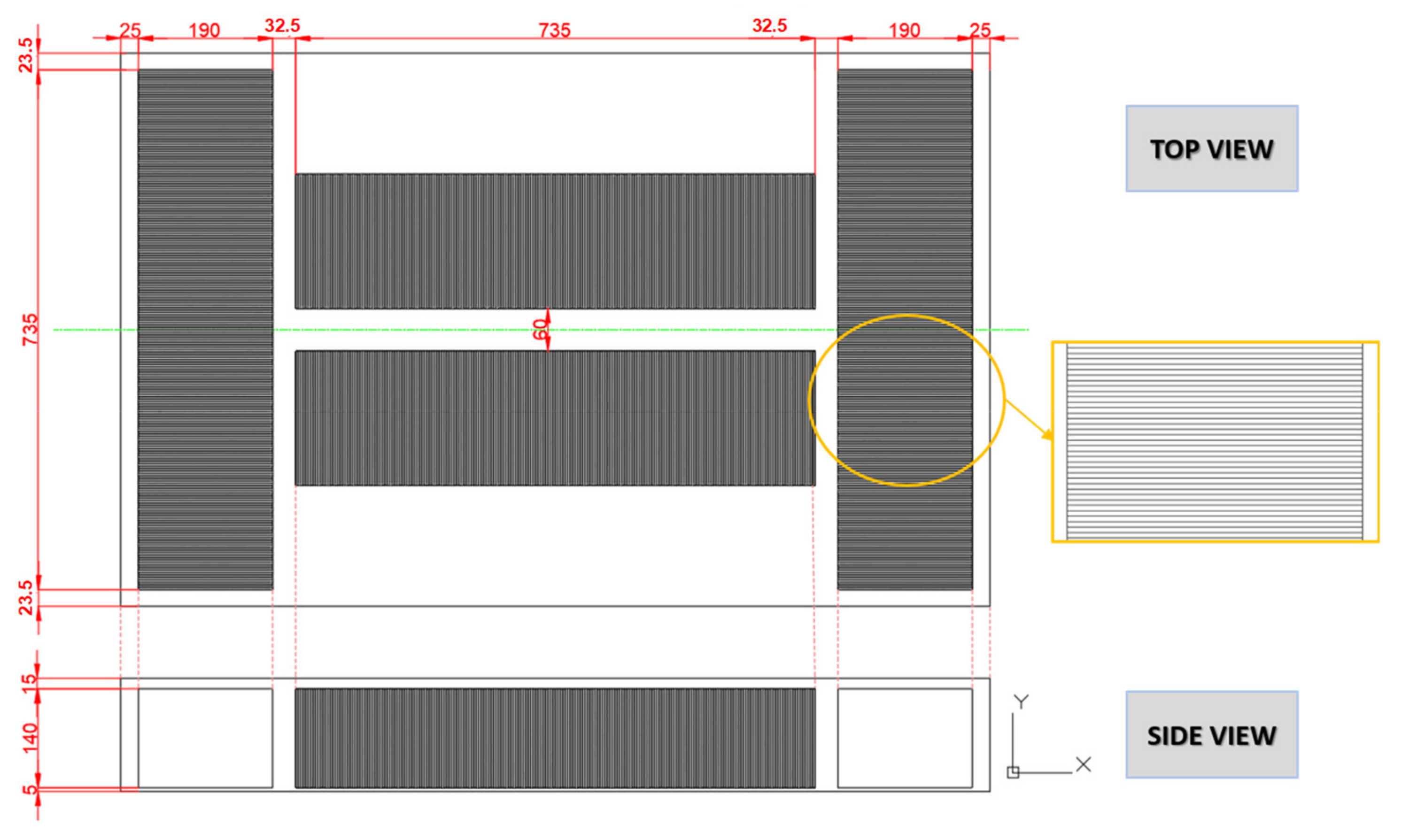
In configuration 4, the dimensions of the modules are not fixed and equal to those of the initial BMWi3 pack. The available space is filled by arranging the cells within the modules and the modules within the pack in the preferred way. The same cell as in configuration 2 and 3 (SCiB 23 Ah) is used. This configuration is obtained by arranging 51 cells in three rows of 17 in each module along the x-direction, and on the y-direction, six cells are considered (see Figure 7).
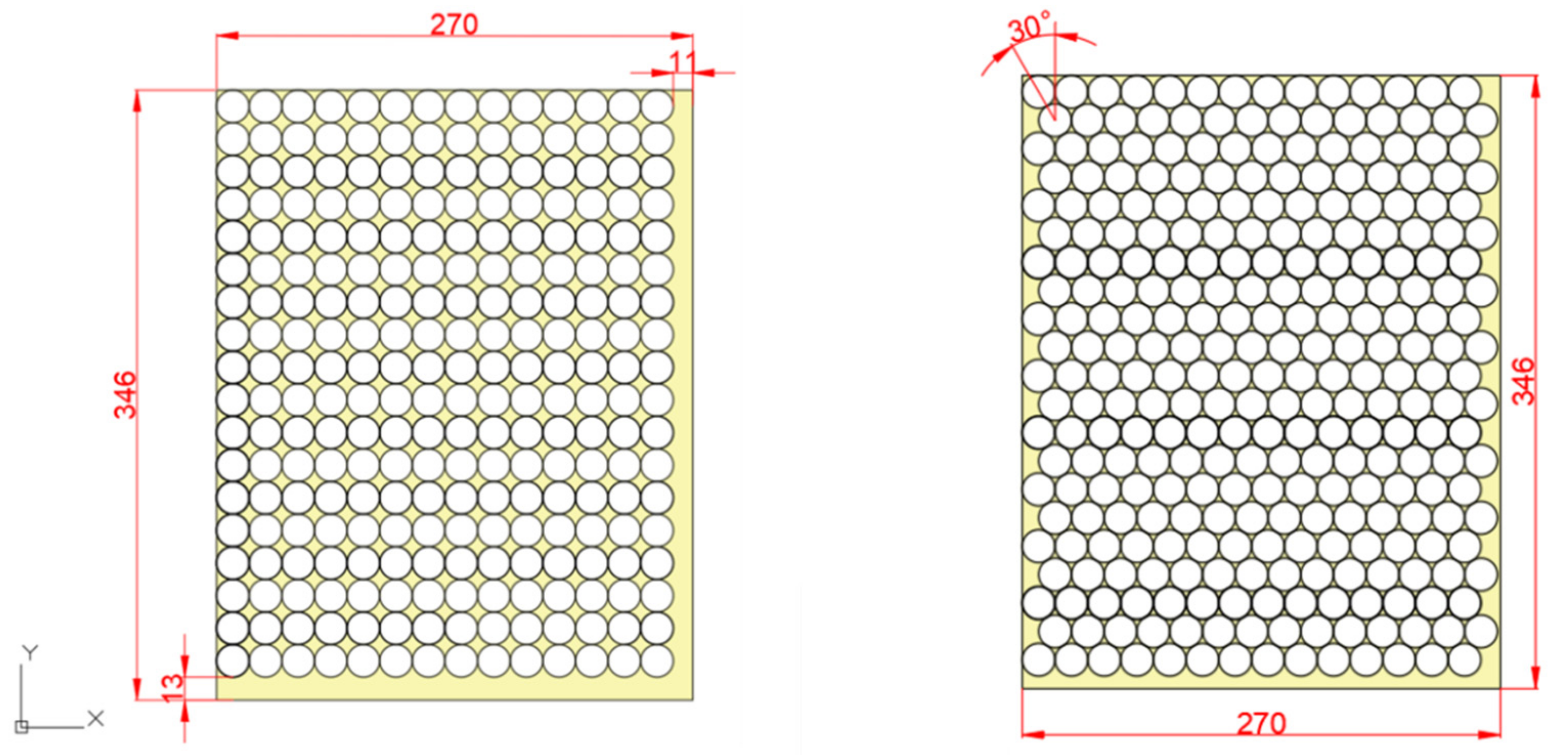
In configurations 5–7, the packaging disposition of cylindrical cells into rectangular modules was analyzed. The cells are placed vertically to the vehicle ground. For the installation of cylindrical cells, the size and shape of the surrounding case depends not only on the number of rows and the number of cylinders per row but also on the angle between the centers of cylinders in adjacent rows. A set of various dispositions with different angles exists, but arrangements with angles of 0° and 30° are often used in practice as they are easy to load. Indeed, two principal arrangements are considered in this design analysis: straight packaging (α = 0°) and offset packaging (α = 30°).
The straight packaging was employed in configuration 5 (Figure 8, left). This arrangement is obtained by positioning the cylinders in such a way that each one is placed in ordered rows, with the centers aligned along the same axis, both in the x-direction and y-direction. The angle obtained between the centers of the circular surfaces of adjacent cylinders in the same row or between two consecutive rows is zero. As a result of the straight cells arrangement, 252 cells per module are obtained and, in total, 2016 cells are inserted in the pack. Figure 8 shows that the module available space is not completely filled.
Configuration 6 is obtained by arranging the cells in the module according to the offset packaging (see Figure 8, right). Once, the diameter of the cells and the dimensions of the module are defined. As Figure 8 clearly shows, with this new arrangement, it is possible to insert in the same available space a greater number of cells, equal to 294 per module. Therefore, it can be deduced that the offset packaging is more efficient from a geometrical perspective.
In configuration 7, the Panasonic 21700 cell, instead of Panasonic 18650, is considered. A comparison between the application of these two cylindrical cells is carried out and two cases are analysed; the first is the configuration with 18650 cell, the latter considers the installation of 21700. The BMWi3 pack weight parameter is fixed, and the capacity is then calculated for both cells.
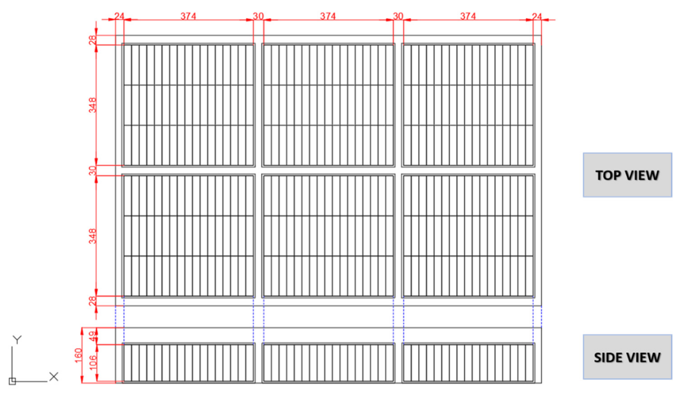
The second Panasonic cell results a in higher capacity, thus representing the best solution. Four modules are considered, as depicted in Figure 9: two of them contain 10 rows of 31 cells each, while in two other modules, 20 rows of 11 cells are alternated with 20 rows of 10 cells. Hence, 840 cells and 1160 cells are, respectively, inserted in the two couples of modules.
Both configurations 8 and 9 investigate the insertion of pouch cells within rectangular cases. Car manufacturers that adopt this cells format usually order them vertically and side by side. This makes pouch cells the technology with the most efficient use of space, thus achieving a considerably high packaging efficiency. However, the dimensions of most of the pouch cells found in the market do not fulfill the geometrical boundaries of the reference module. Pouch cells may also be placed in a flat disposition, parallel to the ground, by considering the cell’s largest surface as the base surface, and overlapping more cells to form the modules. Nevertheless, the amount of pouch cells would be greatly reduced and the existing potential of this cells typology would not be fully exploited. In order to overcome the issue of commercial cells, pouch cells with smaller dimensions manufactured by the Battery LabFactory Braunschweig (BLB) for research purposes were used in the analysis.
Configuration 8 consists of 10 modules, in which the cells are arranged in two different positions: two long modules are placed on the right and left side of the available space with the pouch cells aligned not vertically but laterally (see Figure 10). To overcome the spatial boundary, each cell is rotated 90° with respect to the usual disposition and is oriented in such a way that the cell height is parallel to the ground. Hence, the terminals of both modules are not located in the upper part of modules but they are turned toward the inner space. In this way, two long modules are generated along the y-axis. Another four modules equal to two external ones could be positioned between them, but the electrical connections would be rather difficult. Therefore, a different orientation for the cells was chosen in the remaining volume: two rows of four modules are located in the inner part, each of them containing 40 cells piled on top of one another. In these eight modules, the cells are arranged in a flat position, with the terminals turned toward the center of the battery pack. The cells in the flat position are located in the inner part of the pack volume for guaranteeing safety from eventual external impacts and for improving the vehicle dynamics.
Configuration 9 follows some of assumptions made for configuration 8. Indeed, the two external modules located, respectively, on the left and right side of the battery pack are maintained. The only difference is the arrangement of batteries between the two groups of cells placed at the two sides of the pack: two new modules are placed in the upper and bottom part of the remaining space, as shown in Figure 11.
4.3. Optimized Layout
After defining the strategies to be followed and their application for each cell format, the main technical parameters can be calculated for all the proposed configurations. To this purpose, the technical specifications of the investigated cells are referred and the formulas (1–3) are applied. The results are summarized in Table 4 and a comparison with the reference battery pack is proposed. A new parameter is defined to carry out the comparison and identify the optimal solution: the ratio between the battery pack capacity and weight (ρpack). The cell and pack ratio do not differ as the calculations are based on cell values and the number of cells per pack configuration. As pointed out above, the analysis does not consider various factors that would increase the weight of the pack (i.e., battery pack casing, wiring harnesses, cooling system, etc.), thus affecting the ratios. Based on these assumptions, the ρcell and ρpack, namely, the ratio on cell and pack level, respectively, have the same values.
The data collected for the four prismatic cells configuration do not show improved results with respect to the original BMWi3 values. In fact, the pack capacities are lower and the weight values are higher. The Toshiba SCiB cells lead to a battery pack configuration with a strongly decreased weight, but, on the other hand, the capacity is reduced. This is strongly dependent on the specific cell characteristics: SCiB cells have small dimensions and reduced weight, but they have nominal capacity and voltage values quite lower than the Samsung SDI cells. Configuration 1 is the only case in the prismatic group that provides a high capacity and an acceptable pack weight, although the values are not optimized compared to the original model, having an energy-to-weight ratio equal to 0.17 kWh/kg, the same as the reference.
By using cylindrical cells instead of the prismatic ones, the weight of the pack is halved. However, the capacity is also greatly reduced. For instance, the battery pack manufactured according to configuration 5 would weigh half but would result in a lower capacity. Similar results arise from configuration 6: a higher pack capacity with a considerable reduction in weight. Obviously, the offset packaging allows for inserting more cells in the available space, thus increasing the overall pack capacity. The Panasonic 21700 cells are used in configuration 7, instead, and the new layout results in a battery pack with a considerably higher capacity and lower weight. The three configurations obtained with cylindrical cells exhibit ρpack values that are significantly higher than both the reference model and prismatic cell usage. This means that all the cylindrical study cases offer good energy to weight ratios. The best solution is configuration 7: its ρpack is much higher than the others and, at the same time, is able to provide more capacity with an inferior weight with respect to the BMWi3 configuration.
Finally, the last two configurations with pouch cells show ρpack values that are extremely low if compared to the original BMWi3 energy to weight ratio. In both cases under examination, the pack capacity is much lower than the reference one, whereas the weight is excessive (i.e., over 200 kg). Hence, neither configuration with pouch cells can be considered optimal, despite the pouch format being the technology with the highest expectations. This demonstrates that the cell type and its format do not represent the only factor that influences the performance of the battery pack. The arrangement of cells and the overall disposition of cells and modules in the pack volume also has major relevance.
The reference vehicle BMWi3 is equipped with Samsung SDI 94 Ah prismatic cells. The safe integration of Samsung SDI cells in the battery pack has been validated within the patent published by Samsung and Bosch in 2014 [56].
The results of the proposed methodology show that the configuration that guarantees an optimized battery pack design with respect to the original BMWi3 pack model, based on lower weight and higher pack capacity, is configuration 7 with 21700 Panasonic cylindrical cells, arranged in four modules with an offset packaging. Out of the analyses, these cells turn out to be the best solution for a co-optimized converted design, thanks to their low mass and their high packing efficiency. However, the effect of considering additional parameters and components might significantly influence the outcomes of the analysis. Components to be integrated in the assessment are, for instance, safety devices, battery management system, and cooling devices. Those components have an influence on the space constraints. Factors that could influence the vehicle performance are the safety and vehicle dynamics.
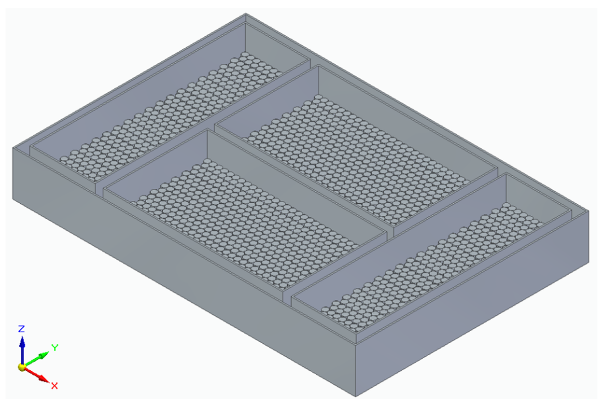
A detailed CAD model of the battery system was thus developed for the chosen configuration (see Figure 12). This solid modelling computer-aided software was used to provide a visual example of how the selected battery pack configuration appears, so as to better understand how the cell typology and the general layout influences the overall design and differs with respect to the reference model depicted in Figure 3.
5. Conclusions and Outlook
This research has aimed at setting-up a design procedure for the optimal installation of battery systems in BEVs, by considering a series of requirements, as well as using an existing vehicle configuration to demonstrate the effectiveness of conversion design strategies in optimizing battery installation effects within electric and hybrid vehicle chassis.
Several factors can indeed influence the choice of the battery technology to be employed, for instance, the specific energy and power required and the battery capacity. In addition, battery durability and longevity, as well as its geometry, weight, costs and security, need to be considered in the design process, especially when selecting the proper battery pack location. Each factor has a certain influence on the overall design of electric vehicles, as it affects crucial aspects, such as the dynamics of the vehicle, the driving stability and the safety of passengers. The proposed design procedure focused on two variables to be manipulated in such a way as to obtain an optimal configuration: the battery pack capacity and weight. The objective of this procedure was to increase the battery capacity while decreasing the overall vehicle weight. In order to fulfil this challenging aim, various cell formats and geometries were investigated and considerations about their arrangement within the module and battery pack were made. After a careful and extended survey on technological and cost aspects, lithium-ion batteries were chosen in the study, as they are increasingly becoming the best choice for automotive applications, due to their higher specific energy density.
The methodology was implemented using as reference a commercially available electric vehicle (BMWi3) and the installed battery cells (Samsung SDI 94 Ah). Different pack filling strategies were developed, depending on the cell format, and the best solutions were identified. Cylindrical cells provided promising results, having as boundary conditions the available space to place the cells, as well as the weight and capacity of the reference battery pack.
Practical guidelines were thus provided, particularly the importance of adopting a conversion design approach, when aiming at improving installation strategies while coping with industrial and customer-relevant aspects (i.e., acceleration performance, fuel economy and/or range). The presented case study can also inspire industrial processes where conversion design is deployed from the very beginning of the entire vehicle design task in such a way as to promote a more effective integration of the main powertrain devices and electric components.
The proposed methodology was applied to rectangular modules. Other geometries of battery packs can be analyzed in future work following a similar approach. Future developments can focus on additional components to be accounted for in the analysis, such as, for instance, the cooling system, the BMS and the electrical connections, adding further degrees of freedom to the methodology. Finally, cost-effectiveness analyses can be included, especially when the above-mentioned highly integrated conversion design approach is selected, opening up the investigation not only to different battery typologies, but also to other technologies and/or even other hybridization devices (e.g., supercapacitors).
Another relevant parameter to be considered in future research is the power capability during charge and discharge. The integration of the peak power in the design methodology is of great importance to assess specific working conditions, i.e., acceleration or fast charging.
This paper shall thus be considered as a basis study to be further investigated. The main aim is to point out how the cells’ disposition and geometry, beyond the pure capacity, impact the design and performance of the pack. Future work can deepen this analysis, including the mechanical, electrical and thermal elements not considered in this study, in such a way as to investigate the same configurations that would reflect the real architectures.
Author Contributions
Conceptualization, E.P., T.V. and M.S.; methodology, E.P. and V.C.; investigation, E.P. and V.C.; writing—original draft preparation, E.P., V.C. and M.S.; writing—review and editing, E.P., T.V., M.S. and V.C.; visualization, V.C.; supervision, E.P., T.V. and M.S. All authors have read and agreed to the published version of the manuscript.
Funding
The authors would like to acknowledge the financial support provided by the European Union, within the framework of the Erasmus + Programme.
Institutional Review Board Statement
Not applicable.
Informed Consent Statement
Not applicable.
Data Availability Statement
Not applicable.
Conflicts of Interest
The authors declare no conflict of interest.
References
- Hernandez, A.U.; Miller, J. Methodological notes: Global vehicle sales database. Int. Counc. Clean Transp. 2015. working paper 2015-7. Available online: https://www.google.com.hk/url?sa=t&rct=j&q=&esrc=s&source=web&cd=&ved=2ahUKEwj8mtOa9tvvAhWFKs0KHXpYCwkQFjABegQIAhAD&url=https%3A%2F%2Fwww.theicct.org%2Fsites%2Fdefault%2Ffiles%2Fpublications%2FWorking_Paper_Global_Vehicle_Sales_Database_2015-7.pdf&usg=AOvVaw0zsFC5BmPeduznnAQ7RXGA (accessed on 20 February 2021).
- Sorrentino, M.; Cirillo, V.; Nappi, L. Development of flexible procedures for co-optimizing design and control of fuel cell hybrid vehicles. Energy Convers. Manag. 2019, 185, 537–551. [Google Scholar] [CrossRef]
- Yong, J.Y.; Ramachandaramurthy, V.K.; Tan, K.M.; Mithulananthan, N. A review on the state-of-the-art technologies of electric vehicle, its impacts and prospects. Renew. Sustain. Energy Rev. 2015, 49, 365–385. [Google Scholar] [CrossRef]
- Esmaili, M.; Shafiee, H.; Aghaei, J. Range anxiety of electric vehicles in energy management of microgrids with controllable loads. J. Energy Storage 2018, 20, 57–66. [Google Scholar] [CrossRef]
- González-Garrido, A.; Thingvad, A.; Gaztañaga, H.; Marinelli, M. Full-scale electric vehicles penetration in the Danish Island of Bornholm—Optimal scheduling and battery degradation under driving constraints. J. Energy Storage 2019, 23, 381–391. [Google Scholar] [CrossRef]
- Pahlavanhoseini, A.; Sepasian, M.S. Optimal planning of PEV fast charging stations using nash bargaining theory. J. Energy Storage 2019, 25, 100831. [Google Scholar] [CrossRef]
- Aziz, M.; Oda, T.; Kashiwagi, T. Extended Utilization of Electric Vehicles and their Re-used Batteries to Support the Building Energy Management System. Energy Procedia 2015, 75, 1938–1943. [Google Scholar] [CrossRef] [Green Version]
- Kempton, W.; Letendre, S.E. Electric vehicles as a new power source for electric utilities. Transp. Res. Part D Transp. Environ. 1997, 2, 157–175. [Google Scholar] [CrossRef]
- Hannan, M.; Hoque, M.; Mohamed, A.; Ayob, A. Review of energy storage systems for electric vehicle applications: Issues and challenges. Renew. Sustain. Energy Rev. 2017, 69, 771–789. [Google Scholar] [CrossRef]
- Shui, L.; Chen, F.; Garg, A.; Peng, X.; Bao, N.; Zhang, J. Design optimization of battery pack enclosure for electric vehicle. Struct. Multidiscip. Optim. 2018, 58, 331–347. [Google Scholar] [CrossRef]
- Grunditz, E.A.; Thiringer, T. Performance Analysis of Current BEVs Based on a Comprehensive Review of Specifications. IEEE Trans. Transp. Electrif. 2016, 2, 270–289. [Google Scholar] [CrossRef]
- Schuh, G.; Korthals, K.; Arnoscht, J. Contribution of Body Lightweight Design to the Environmental Impact of Electric Vehicles. Adv. Mater. Res. 2014, 907, 329–347. [Google Scholar] [CrossRef]
- Brown, A.; Harris, W. A Vehicle Design and Optimization Model for On-Demand Aviation. In Proceedings of the 2018 AIAA/ASCE/AHS/ASC Structures, Structural Dynamics, and Materials Conference, Kissimmee, FL, USA, 8–12 January 2018. [Google Scholar] [CrossRef] [Green Version]
- U.S. Department of Energy—Energy Efficiency and Renewable Energy. 2011 Annual Progress Report Energy Storage R&D. Department of Energy (DOE). 2011. Available online: https://www.energy.gov/sites/prod/files/2014/04/f14/cover_toc_0.pdf (accessed on 20 February 2021).
- Boulanger, A.G.; Chu, A.C.; Maxx, S.; Waltz, D.L. Vehicle Electrification: Status and Issues. Proc. IEEE 2011, 99, 1116–1138. [Google Scholar] [CrossRef] [Green Version]
- Un-Noor, F.; Padmanaban, S.; Mihet-Popa, L.; Mollah, M.N.; Hossain, E. A Comprehensive Study of Key Electric Vehicle (EV) Components, Technologies, Challenges, Impacts, and Future Direction of Development. Energies 2017, 10, 1217. [Google Scholar] [CrossRef] [Green Version]
- Andwari, A.M.; Pesiridis, A.; Rajoo, S.; Martinez-Botas, R.; Esfahanian, V. A review of Battery Electric Vehicle technology and readiness levels. Renew. Sustain. Energy Rev. 2017, 78, 414–430. [Google Scholar] [CrossRef]
- Subramaniyam, K.V.; Kumar, C.S.N.; Subramanian, S.C. Analysis of Handling Performance of Hybrid Electric Vehicles. IFAC-PapersOnLine 2018, 51, 190–195. [Google Scholar] [CrossRef]
- Li, W.; Garg, A.; Xiao, M.; Peng, X.; Le Phung, M.L.; Tran, V.M.; Gao, L. Intelligent optimization methodology of battery pack for electric vehicles: A multidisciplinary perspective. Int. J. Energy Res. 2020, 44, 9686–9706. [Google Scholar] [CrossRef]
- Kampker, A. Elektromobilproduktion; Springer Vieweg: Berlin/Heidelberg, Germany, 2014. [Google Scholar] [CrossRef]
- Wallentowitz, H.; Freialdenhoven, A.; Olschewski, I. Strategien zur Elektrifizierung des Antriebstranges (Strategies for the Electrification of the Drive Train); Vieweg + Teubner: Berlin/Heidelberg, Germany, 2010. [Google Scholar]
- Meissner, E.; Richter, G. The challenge to the automotive battery industry: The battery has to become an increasingly integrated component within the vehicle electric power system. J. Power Source 2005, 144, 438–460. [Google Scholar] [CrossRef]
- Danquah, B.; Koch, A.; Weis, T.; Lienkamp, M.; Pinnel, A. Modular, Open Source Simulation Approach: Application to Design and Analyze Electric Vehicles. In Proceedings of the 2019 Fourteenth International Conference on Ecological Vehicles and Renewable Energies (EVER), Monte-Carlo, Monaco, 8–10 May 2019; pp. 1–8. [Google Scholar] [CrossRef]
- Kurfer, J.; Westermeier, M.; Tammer, C.; Reinhart, G. Production of large-area lithium-ion cells–Preconditioning, cell stacking and quality assurance. CIRP Ann. 2012, 61, 1–4. [Google Scholar] [CrossRef]
- Maiser, E. Battery packaging—Technology review. Review on Electrochemical Storage Materials and Technology. In Proceedings of the 1st International Freiberg Conference on Electrochemical Storage Materials, Freiberg, Germany, 3–4 June 2014; Volume 1597, pp. 204–218. [Google Scholar] [CrossRef]
- Wagner, R.; Preschitschek, N.; Passerini, S.; Leker, J.; Winter, M. Current research trends and prospects among the various materials and designs used in lithium-based batteries. J. Appl. Electrochem. 2013, 43, 481–496. [Google Scholar] [CrossRef]
- Barai, A.; Ashwin, T.; Iraklis, C.; McGordon, A.; Jennings, P. Scale-up of lithium-ion battery model parameters from cell level to module level–identification of current issues. Energy Procedia 2017, 138, 223–228. [Google Scholar] [CrossRef]
- Murashko, K.; Pyrhonen, J.; Laurila, L. Three-Dimensional Thermal Model of a Lithium Ion Battery for Hybrid Mobile Working Machines: Determination of the Model Parameters in a Pouch Cell. IEEE Trans. Energy Convers. 2013, 28, 335–343. [Google Scholar] [CrossRef]
- Chen, X.; Gu, C.; Yin, J.; Tang, F.; Wang, X. An overview of distributed drive electric vehicle chassis integration. In Proceedings of the 2014 IEEE Conference and Expo Transportation Electrification Asia-Pacific (ITEC Asia-Pacific), Beijing, China, 31 August–3 September 2014; pp. 1–5. [Google Scholar]
- Tie, S.F.; Tan, C.W. A review of energy sources and energy management system in electric vehicles. Renew. Sustain. Energy Rev. 2013, 20, 82–102. [Google Scholar] [CrossRef]
- Li, L.; Wu, Z.; Yuan, S.; Zhang, X.-B. Advances and challenges for flexible energy storage and conversion devices and systems. Energy Environ. Sci. 2014, 7, 2101–2122. [Google Scholar] [CrossRef]
- Hofer, J.; Wilhelm, E.; Schenler, W. Optimal Lightweighting in Battery Electric Vehicles. World Electr. Veh. J. 2012, 5, 751–762. [Google Scholar] [CrossRef] [Green Version]
- Xu, B.; Oudalov, A.; Ulbig, A.; Andersson, G.; Kirschen, D.S. Modeling of Lithium-Ion Battery Degradation for Cell Life Assessment. IEEE Trans. Smart Grid 2018, 9, 1131–1140. [Google Scholar] [CrossRef]
- Berckmans, G.; Messagie, M.; Smekens, J.; Omar, N.; Vanhaverbeke, L.; Van Mierlo, J. Cost Projection of State of the Art Lithium-Ion Batteries for Electric Vehicles Up to 2030. Energies 2017, 10, 1314. [Google Scholar] [CrossRef] [Green Version]
- Qi, C.; Helian, Y.; Liu, J.; Zhang, L. Experiment Study on the Thermal Comfort inside a Car Passenger Compartment. Procedia Eng. 2017, 205, 3607–3614. [Google Scholar] [CrossRef]
- Stevan, K.; Aleksandar, K.; Atanas, K. Risks and safety issues related to use of electric and hybrid vehicles. Trans Motauto World 2017, 2, 37–40. [Google Scholar]
- Reif, R.; Liffers, M.; Forrester, N.; Peal, K. Lithium Battery Safety. Environmental Health and Safety. 2018. Available online: https://www.ehs.washington.edu/resource/lithium-battery-safety-732 (accessed on 20 February 2021).
- Fotouhi, A.; Auger, D.J.; Cleaver, T.; Shateri, N.; Propp, K.; Longo, S. Influence of battery capacity on performance of an electric vehicle fleet. In Proceedings of the 2016 IEEE International Conference on Renewable Energy Research and Applications (ICRERA), Birmingham, UK, 23–26 November 2016; pp. 928–933. [Google Scholar] [CrossRef] [Green Version]
- Heacock, D.; Freeman, D. Capacity monitoring in advanced battery chemistries. In Proceedings of the Tenth Annual Battery Conference on Applications and Advances, Long Beach, CA, USA, 6 August 2002; pp. 185–191. [Google Scholar]
- Pollet, B.G.; Staffell, I.; Shang, J.L. Current status of hybrid, battery and fuel cell electric vehicles: From electrochemistry to market prospects. Electrochim. Acta 2012, 84, 235–249. [Google Scholar] [CrossRef]
- Han, W.; Zou, C.; Zhou, C.; Zhang, L. Estimation of Cell SOC Evolution and System Performance in Module-Based Battery Charge Equalization Systems. IEEE Trans. Smart Grid 2019, 10, 4717–4728. [Google Scholar] [CrossRef]
- Berjoza, D.; Jurgena, I. Influence of batteries weight on electric automobile performance. Eng. Rural Dev. 2017, 16, 1388–1394. [Google Scholar] [CrossRef]
- Reński, A.; National Highway Traffic Safety Administration. Investigation of the Influence of the Centre of Gravity Position on the Course of Vehicle Rollover. In Proceedings of the 24th International Technical Conference on the Enhanced Safety of Vehicles (ESV) National Highway Traffic Safety Administration, Gothenburg, Sweden, 8–11 June 2015; pp. 8–11. [Google Scholar]
- Doumiati, M.; Victorino, A.; Charara, A.; Lechner, D. Lateral load transfer and normal forces estimation for vehicle safety: Experimental test. Veh. Syst. Dyn. 2009, 47, 1511–1533. [Google Scholar] [CrossRef]
- Berjoza, D.; Jurgena, I. Effects of change in the weight of electric vehicles on their performance characteristics. Agron. Res. 2017, 15, 952–963. [Google Scholar]
- Becker, J.; Nemeth, T.; Wegmann, R.; Sauer, D.U. Dimensioning and Optimization of Hybrid Li-Ion Battery Systems for EVs. World Electr. Veh. J. 2018, 9, 19. [Google Scholar] [CrossRef] [Green Version]
- Van Vliet, O.; Brouwer, A.S.; Kuramochi, T.; Broek, M.V.D.; Faaij, A. Energy use, cost and CO2 emissions of electric cars. J. Power Source 2011, 196, 2298–2310. [Google Scholar] [CrossRef] [Green Version]
- Ribeiro, B.; Brito, F.; Martins, J. A Survey on Electric/Hybrid Vehicles. In SAE Technical Paper Series; SAE: Warrendale, PA, USA, 2010. [Google Scholar] [CrossRef] [Green Version]
- Trattnig, G.; Leitgeb, W. Automotive Battery Technology; Springer: Berlin/Heidelberg, Germany, 2014. [Google Scholar]
- Yang, S.; Lu, Y.; Li, S. An overview on vehicle dynamics. Int. J. Dyn. Control. 2013, 1, 385–395. [Google Scholar] [CrossRef] [Green Version]
- Zeng, B.; Liu, X.; Zhang, Y. The Structure Optimization Analysis of Electric Vehicle in Small Offset Rear End Collision. Procedia Eng. 2016, 137, 103–108. [Google Scholar]
- Kong, L.; Li, C.; Jiang, J.; Pecht, M.G. Li-Ion Battery Fire Hazards and Safety Strategies. Energies 2018, 11, 2191. [Google Scholar] [CrossRef] [Green Version]
- Groupe Bolloré. Blue Solutions Business Report. 2013. Available online: https://www.blue-solutions.com/en/blue-solutions/investissors/informations-reglementees/ (accessed on 20 February 2021).
- Miri, I.; Fotouhi, A.; Ewin, N. Electric vehicle energy consumption modelling and estimation—A case study. Int. J. Energy Res. 2021, 45, 501–520. [Google Scholar] [CrossRef]
- BMW Group. Technical Specifications for the BMW i3 (94Ah), Valid from 07/2016. 19–20 (2016). Available online: https://www.press.bmwgroup.com/global/article/search/tag:84,136/ (accessed on 20 February 2021).
- Schneider, J.; Heubner, A.; Reinshagen, H. Patent Application Publication Safety device for arrangement in a battery cell of a Lithium-Ion Battery, Lithium-Ion Battery cell with safety device. U.S. Patent Application 14/057,323, 24 April 2014. [Google Scholar]
Figure 1.
Installation and integration of battery pack into the vehicle: Overview of possible locations. The options (A–D) are based on a benchmarking of available concepts; options (E–H) are possible solutions to be explored, not yet used in the automotive market.
Figure 1.
Installation and integration of battery pack into the vehicle: Overview of possible locations. The options (A–D) are based on a benchmarking of available concepts; options (E–H) are possible solutions to be explored, not yet used in the automotive market.

Figure 2.
Proposed conversion design methodology to optimize battery pack weight and capacity, based on the available pack size within the chosen vehicle configuration.
Figure 2.
Proposed conversion design methodology to optimize battery pack weight and capacity, based on the available pack size within the chosen vehicle configuration.

Figure 3.
BMWi3 battery pack schematic (reference) in floor integration installation (configuration B).
Figure 3.
BMWi3 battery pack schematic (reference) in floor integration installation (configuration B).

Figure 4.
Pack schematic of configuration 1 with prismatic cells in the floor integration installation of reference vehicle.
Figure 4.
Pack schematic of configuration 1 with prismatic cells in the floor integration installation of reference vehicle.

Figure 5.
Reference module filling algorithms used in configuration 2 and 3.

Figure 6.
Toshiba SCiB cell disposition in one module, developed for configuration 2 (left side) and 3 (right side).
Figure 6.
Toshiba SCiB cell disposition in one module, developed for configuration 2 (left side) and 3 (right side).

Figure 7.
Pack schematic of configuration 4 with prismatic cells in the floor integration installation of reference vehicle.
Figure 7.
Pack schematic of configuration 4 with prismatic cells in the floor integration installation of reference vehicle.

Figure 8.
Reference module schematic with cylindrical cells arranged according to straight packing (left) and offset packing (right).
Figure 8.
Reference module schematic with cylindrical cells arranged according to straight packing (left) and offset packing (right).

Figure 9.
Pack schematic of configuration 7 with Panasonic 21700 cylindrical cells in the floor integration installation of reference vehicle.
Figure 9.
Pack schematic of configuration 7 with Panasonic 21700 cylindrical cells in the floor integration installation of reference vehicle.

Figure 10.
Pack schematic of configuration 8 with BLB2 pouch cells in the floor integration installation of reference vehicle.
Figure 10.
Pack schematic of configuration 8 with BLB2 pouch cells in the floor integration installation of reference vehicle.

Figure 11.
Pack schematic of configuration 9 with BLB2 pouch cells in the floor integration installation of reference vehicle.
Figure 11.
Pack schematic of configuration 9 with BLB2 pouch cells in the floor integration installation of reference vehicle.

Figure 12.
CAD model of the optimal configuration (Configuration 7 with 21700 Panasonic cylindrical cells, arranged in four modules with an offset packaging).
Figure 12.
CAD model of the optimal configuration (Configuration 7 with 21700 Panasonic cylindrical cells, arranged in four modules with an offset packaging).


Table 1.
Battery requirements matrix for electric vehicle chassis integration [9,29,30,31,32,33,34,35,36,37].
| Group | Requirement | Description | |
|---|---|---|---|
| Energy | High Efficiency | Depends on the usage of the energy storage system (ESS) and is strongly influenced by charging, discharging. | |
| High longevity and durability | Resistance to adverse temperature, charge/discharge cycles | ||
| Good Performance | High capacity | Determines the EV range | |
| High specific energy | The higher the specific energy, the greater the amount of energy that the battery can retain. Influences the EV autonomy | ||
| High specific power | Allows fast charging and long storage | ||
| Initial manufacturing cost | Low production cost | ||
| Low material cost | |||
| Low error cost | |||
| Mechanics | Cell geometry | Makes good use of the available space | |
| Location | Protection against stresses and collisions | ||
| Separation from passenger compartment | |||
| Stability | Low center of gravity | ||
| Minimum stack weight | |||
| Good weight distribution | |||
| Safety | Access for maintenance | Easily accessible for testing, cleaning, replacement, tightening of connections and periodic servicing | |
| Protection against temperature changes | Integration of heating and cooling system to avoid cell degradation | ||
| Crash safety | To avoid explosions | ||
| Environment | Recycling | Appropriate recycling practices | |
| Disposal | Due to the presence of heavy metals and toxic chemicals and materials, batteries cannot be disposed of as solid waste | ||
Table 2.
Technical specifications of the battery pack for the commercial vehicle BMWi3 (94 Ah) Reproduced from [55], BMW 2016.
Table 2.
Technical specifications of the battery pack for the commercial vehicle BMWi3 (94 Ah) Reproduced from [55], BMW 2016.
| High-Voltage Battery Pack | |
|---|---|
| Pack Location | Floor integration |
| Rated Voltage, V | 353 |
| Nominal energy capacity, kWh | 33.2 |
| Usable energy capacity, kWh | 27.2 |
| Pack Weight, kg | 198 |
| Module | |
| Nr modules | 8 |
| Nr cells per module | 12 |
| Cell | |
| Geometry | Prismatic |
| Typology | Lithium-ion |
| Manufacturer | Samsung SDI |
| Nominal capacity, Ah | 94 |
| Nominal voltage, V | 3.68 |
| Energy, kWh | 350 |
| Size (L × W × H), mm | 173 × 125 × 45 |
| Weight, kg | 2.06 |
Table 3.
Strategies for cell and module disposition in the specific battery pack configurations with prismatic, cylindrical and pouch-cell formats.
Table 3.
Strategies for cell and module disposition in the specific battery pack configurations with prismatic, cylindrical and pouch-cell formats.
| Cell format | Configuration | Battery Cell Type | Filling Strategy |
|---|---|---|---|
| Prismatic | 1 | Samsung SDI 94 Ah | Cell rotation |
| 2 | Toshiba SCiB 23 Ah | Algorithm 1 | |
| 3 | Toshiba SCiB 23 Ah | Algorithm 2 | |
| 4 | Toshiba SCiB 23 Ah | Re-arrangement of modules | |
| Cylindrical | 5 | Panasonic 18650 | Original vehicle module size + straight packaging (α = 0°) |
| 6 | Panasonic 18650 | Original vehicle module size + offset packaging (α = 30°) | |
| 7 | Panasonic 21700 | Rearrangement of modules + offset packaging (α = 30°) | |
| Pouch | 8 | BLB2 | Rearrangement of modules (lateral + flat cells disposition) |
| 9 | BLB2 | Rearrangement of modules (only lateral cells disposition) |
Table 4.
Summary table of all pack configurations with prismatic, cylindrical and pouch cell format.
Table 4.
Summary table of all pack configurations with prismatic, cylindrical and pouch cell format.
| Group | Configuration | Cell Type | ρcell [kWh/kg] | Nr Modules | Nr Cells | Pack Capacity [kWh] | Pack Weight [kg] | ρpack [kWh/kg] |
|---|---|---|---|---|---|---|---|---|
| BMWi3 | Reference | Samsung SDI 94 Ah | 0.17 | 8 | 96 | 33 | 198 | 0.17 |
| Prismatic cell | 1 | Samsung SDI 94 Ah | 0.17 | 9 | 90 | 31.2 | 185.4 | 0.17 |
| 2 | Toshiba SCiB 23 Ah | 0.10 | 8 | 256 | 13.5 | 129.3 | 0.10 | |
| 3 | Toshiba SCiB 23 Ah | 0.10 | 8 | 272 | 14.4 | 137.4 | 0.10 | |
| 4 | Toshiba SCiB 23 Ah | 0.10 | 6 | 306 | 16.8 | 154.5 | 0.11 | |
| Cylindrical cell | 5 | Panasonic 18650 | 0.24 | 8 | 2016 | 23.2 | 97.8 | 0.24 |
| 6 | Panasonic 18650 | 0.24 | 8 | 2352 | 27 | 114 | 0.24 | |
| 7 | Panasonic 21700 | 0.25 | 4 | 2000 | 34.6 | 136 | 0.25 | |
| Pouch cell | 8 | BLB2 | 0.11 | 4 | 740 | 23 | 214.6 | 0.11 |
| 9 | BLB2 | 0.11 | 4 | 840 | 26.1 | 243.6 | 0.11 |
Publisher’s Note: MDPI stays neutral with regard to jurisdictional claims in published maps and institutional affiliations. |
© 2021 by the authors. Licensee MDPI, Basel, Switzerland. This article is an open access article distributed under the terms and conditions of the Creative Commons Attribution (CC BY) license (https://creativecommons.org/licenses/by/4.0/).
Share and Cite
MDPI and ACS Style
Pierri, E.; Cirillo, V.; Vietor, T.; Sorrentino, M. Adopting a Conversion Design Approach to Maximize the Energy Density of Battery Packs in Electric Vehicles. Energies 2021, 14, 1939. https://doi.org/10.3390/en14071939
AMA Style
Pierri E, Cirillo V, Vietor T, Sorrentino M. Adopting a Conversion Design Approach to Maximize the Energy Density of Battery Packs in Electric Vehicles. Energies. 2021; 14(7):1939. https://doi.org/10.3390/en14071939
Chicago/Turabian StylePierri, Erika, Valentina Cirillo, Thomas Vietor, and Marco Sorrentino. 2021. "Adopting a Conversion Design Approach to Maximize the Energy Density of Battery Packs in Electric Vehicles" Energies 14, no. 7: 1939. https://doi.org/10.3390/en14071939
Note that from the first issue of 2016, this journal uses article numbers instead of page numbers. See further details here.