Review

Ga2O3 and Related Ultra-Wide Bandgap Power Semiconductor Oxides: New Energy Electronics Solutions for CO2 Emission Mitigation

by
Zeyu Chi
1,†,
Jacob J. Asher
2,†,
Michael R. Jennings
2,
Ekaterine Chikoidze
1 and
Amador Pérez-Tomás
3,*
1
Groupe d’Etude de la Matière Condensée (GEMaC), UVSQ-CNRS, Université Paris-Saclay, 45 Av. des Etats-Unis, CEDEX, 78035 Versailles, France
2
Bay Campus, College of Engineering, Swansea University, Fabian Way, Crymlyn Burrows, Swansea SA1 8EN, UK
3
Catalan Institute of Nanoscience and Nanotechnology (ICN2), CSIC and BIST, Campus UAB, Bellaterra, 08193 Barcelona, Spain
*
Author to whom correspondence should be addressed.
These authors contributed equally to this work.
Materials 2022, 15(3), 1164; https://doi.org/10.3390/ma15031164
Submission received: 17 December 2021 / Revised: 14 January 2022 / Accepted: 25 January 2022 / Published: 2 February 2022
(This article belongs to the Special Issue Feature Papers in Electronic Materials Section)

Abstract

:
Currently, a significant portion (~50%) of global warming emissions, such as CO2, are related to energy production and transportation. As most energy usage will be electrical (as well as transportation), the efficient management of electrical power is thus central to achieve the XXI century climatic goals. Ultra-wide bandgap (UWBG) semiconductors are at the very frontier of electronics for energy management or energy electronics. A new generation of UWBG semiconductors will open new territories for higher power rated power electronics and solar-blind deeper ultraviolet optoelectronics. Gallium oxide—Ga2O3 (4.5–4.9 eV), has recently emerged pushing the limits set by more conventional WBG (~3 eV) materials, such as SiC and GaN, as well as for transparent conducting oxides (TCO), such asIn2O3, ZnO and SnO2, to name a few. Indeed, Ga2O3 as the first oxide used as a semiconductor for power electronics, has sparked an interest in oxide semiconductors to be investigated (oxides represent the largest family of UWBG). Among these new power electronic materials, AlxGa1-xO3 may provide high-power heterostructure electronic and photonic devices at bandgaps far beyond all materials available today (~8 eV) or ZnGa2O4 (~5 eV), enabling spinel bipolar energy electronics for the first time ever. Here, we review the state-of-the-art and prospects of some ultra-wide bandgap oxide semiconductor arising technologies as promising innovative material solutions towards a sustainable zero emission society.

1. Introduction

According to the latest Intergovernmental Panel on Climate Change (IPCC) report released in August 2021 [1], climate change is widespread, rapid, and intensifying and some trends are now regarded as irreversible. Human-induced climate change is already affecting many weather and climate extremes in every region across the globe. Scientists are also observing changes across the whole Earth’s climate system; in the atmosphere, in the oceans, ice floes, and on land. Many of these changes are unprecedented and some of the shifts are now in motion, while some—such as rising sea levels—are already irreversible for the coming centuries to millennia. Stabilizing the climate will require strong, rapid, and sustained reductions in greenhouse gas emissions, and reaching net zero CO2 emissions. Limiting other greenhouse gases and air pollutants, especially methane, could be beneficial for the health of the climate as well as the population [1]. The breakdown for the different greenhouse gas emissions can be seen in Figure 1 [2], where transport and electrical production account for up to 40%. Therefore, many energy-related megatrends of our modern society must focus on themes such as energy efficiency, e-mobility, smart grid and digitalization requiring green energy management electronics or power electronic solutions [3].
Around half of the power used in the world is electrical and this is expected to increase steadily in the near future [5]. The vast majority (if not all) of this electricity will flow through, at least, one power electronic device during its generation, transmission, and final use. This is a critical aspect of power management which is sometimes overlooked, as power electronics make renewable (and non-renewable) energy impactful by increasing their efficiency [6]. As Si-based devices are replaced with other materials which are more energy efficient, this will affect the overall power consumption which will have a knock-on effect on CO2 emissions by a significant amount [7]. Furthermore, devices made with a semiconductor having a bandgap larger than silicon can be made with less material and have lower cooling requirements, hence saving a lot of space and weight in applications such as electrical transport. This integration obviously impacts the amount of power required and, therefore, saves energy and its associated emissions. Since the 1980s, there has been a lot of work towards replacing silicon-based (E-gap of 1.12 eV) power electronics devices with wide bandgap (3–3.4 eV) semiconductor (WBG) based devices (in particular, silicon carbide (SiC) and gallium nitride (GaN)) and power devices with superior specs (higher temperature of operation, higher power handling capability, etc.) are now commercially available (typically in the range of 650 V–3.5 kV) [8,9] (Figure 1). While SiC devices and GaN transistors are already qualified in many emerging applications, silicon-based devices are still dominating in most applications. There are several reasons for this dominance, to start with, Si-based devices still have substantial potential. Their electrical and thermal performance is outstanding, their reliability is proven as can be seen from their years in application, as well as their low cost. In contrast WBG devices are starting their development, where we are still learning about materials development and device design. The benefits on the system level needs to be qualified and long-term reliability issues need to be determined; as these materials are developed, the costs for high-quality large volume production should decrease.
More recently, the frontier in the field is now given by ultra-wide bandgap semiconductors (UWBG), which have the promise of further upshifting the power rating and operation temperature. The same UWBG oxides also offer the potential for deeper ultraviolet optoelectronics [10]. Although another UWBG semiconductor, diamond, has been investigated over the last forty years, there has been limited progress and only recently have other materials, such as gallium oxide (Ga2O3) or aluminum nitride (AlN), yielded device demonstrations with appropriate performances. In particular, Ga2O3 is a newer UWBG material (4.5–5 eV) and is receiving a lot of attention as a novel semiconductor, owing to its unusual material properties. The doping (n-type) is very tunable with an extremely high breakdown field and unique optoelectronic properties, these alongside the possibility of growing large native substrates (over 6″) with a low cost [11]. Besides, representing the first viable oxide semiconductor for power electronics, Ga2O3 has opened the door to many more oxide compounds to be scrutinized (e.g., spinel ZnGa2O4) as they represent the largest family of ultra-wide bandgap semiconductors. UWBG oxide semiconductors are now at the very frontier of energy electronics, and much cutting-edge research, challenges, and opportunities are taking place [12]. These will be succinctly overviewed in this paper.

2. Oxide Semiconductors for Power Electronics

As an alternative to silicon, there is a new generation of wide bandgap semiconductors which have the capability to operate at higher voltages, temperatures, and switching frequencies with greater efficiencies compared to existing Si devices. This characteristic results in lower losses and enables significantly reduced volume due to decreased cooling requirements and smaller passive components contributing to overall lower system cost. Wide bandgap semiconductors (in the context of power electronic devices) usually represent materials whose band gap is larger than that of silicon. A (non-exhaustive) list of different wide bandgap semiconductors is presented in Figure 2. There are several families of wide bandgap semiconductors depending on their chemical composition. The III–V wide bandgap semiconductors are primarily nitrides, phosphides, and arsenides. Chalcogen semiconductors are those containing a transition metal and a chalcogen anion (S, Se, or Te), therefore forming sulfides, selenides, and tellurides. There are few halogen wide bandgap semiconductors in the form of chloride, iodides, and bromides. Silicon carbide (which exhibits a very large number of polytypes) and diamond are both carbon-based materials. SiC is a relevant wide bandgap semiconductor since it is the only compound semiconductor that can be thermally oxidized to form SiO2 in the same fashion as silicon [13].
A special case of chalcogenides would be oxides; although group 16 is defined as chalcogens, the term chalcogenide is more commonly reserved for sulfides, selenides, and tellurides only. Oxides are ubiquitous in nature due to the large abundance of oxygen in the earth and the large oxygen electronegativity (i.e., the atom tendency to attract electrons and thus form bonds) that easily creates largely covalent stable chemical bonds with almost all elements to give the corresponding oxides. Indeed, almost the entire Earth’s crust parts are oxides as the individual crust elements are inclemently oxidized by the oxygen present in the atmosphere or in the water [14]. Besides, the Earth’s mantle (which represents 60–70% and ~80% of the Earth’s mass and volume, respectively) is predominantly a layer of silicate (i.e., compounds containing silicon and oxygen including silica, orthosilicates, metasilicates, pyrosilicates, etc.) and magnesium oxide (MgO)-rich rock between the crust and the outer core [14]. The upper mantle is dominantly peridotite, composed primarily of variable proportions of the minerals olivine ((Mg,Fe)2SiO4), pyroxenes (XY(Si,Al)2O6), and aluminous phases, such as feldspar (NaAlSi3O8–CaAl2Si2O8) and spinel (MgAl2O4). The lower mantle is composed primarily of bridgmanite ((Mg, Fe)SiO3) and ferropericlase ((Mg, Fe)O), with significant amounts of calcium perovskite (CaSiO3) and calcium-ferrite oxides [15].
Thus, in general, oxides can be regarded as naturally abundant and stable compounds. Since the early days of solid-state physics, (undoped) oxides have been considered to be insulators (or more precisely, highly resistive wide bandgap semiconductors). The bandgap of many common oxides, such as Al2O3, SnO2, TiO2, In2O3, Cu2O, WO3, ZnO, or NiO, is much wider than that of silicon (1.12 eV). Therefore, they are intrinsically poor conductors at room temperature if they are not properly doped into a degenerated state. Recently, much effort has been put into increasing the conductivity of some of these oxides (in particular those where s and p electrons propagate with a large mobility) while maintaining the optical transparency. Good examples are the doping of Al in ZnO, Sn in In2O3, and F in SnO2, which are known as transparent conducting oxides (TCOs).
In practice, wide bandgap materials of choice have a bandgap of around ~3 eV, with silicon carbide and gallium nitride in a prominent position. Recently, a new family of semiconductor materials with even larger bandgaps (known as ultra-wide bandgap semiconductors) is being investigated for the new generation of optoelectronic and power electronic applications. As a rule of thumb, an ultra-wide bandgap semiconductor is one with a band gap larger than that of GaN (i.e., 3.4 eV). Perhaps the most investigated ultra-wide bandgap semiconductors are diamond, some nitrides (AlGaN, AlN, and BN), and few oxides. Among oxides, gallium oxide (Ga2O3) is the only oxide semiconductor with ultra-large bandgap where it is possible to modulate the conductivity (i.e., doping) to define power electronic devices. SiC and GaN power devices have already attracted much attention in higher efficiency electrical power conversion [4]. The major advantage of β-Ga2O3 is that the single crystal structure can be synthesized via several standard melt growth methods, e.g., the Czochralski (CZ) technique. This is a huge advantage of Ga2O3 over SiC, GaN, and diamond for scaling up production, hence we would expect the cost of β-Ga2O3 power electronics to decrease and be more in line with silicon with respect to their SiC and GaN counterparts [16,17].

3. Gallium Oxide (Ga2O3)

Ga2O3 has, at least, six polymorphs of which only one is thermodynamically stable at high temperatures (β phase, monoclinic), while the others are metastable and tend to convert to β upon high-temperature treatments including the phases α, corundum, δ, cubic, and ε, hexagonal, γ, defective-spinel, and orthorhombic κ polymorph [18]. The basic principles of polymorphism in crystals are clear: the lattices adapt to the minimum energy with respect to the temperature and pressure. Nearly all Ga2O3-containing devices utilize the monoclinic β phase, the most stable and best-characterized polymorph. As a well-known representative of a binary metal-oxide, gallium oxide cannot therefore be regarded as a new material, but as a revisited and rejuvenated one. For example, early crystallographic studies for single crystals [19] together with diverse luminescence studies of doped β-Ga2O3 were reported as early as the1960s [20]. Lorenz et al. [21] already published in 1966 that n-type Ga2O3 exhibits mobilities in the range of 100 cm2V−1s−1 and an adequate device doping of 1018 cm−3 can be achieved just by controlling the native oxygen vacancies’ density. Its deep-ultraviolet intrinsic bandgap of around 4.5–4.9 eV and excellent photoconductivity are also well-known from early contemporary studies [22]. It was not until this decade that the potential of Ga2O3 for a certain class of extreme or power electronics was realized due to further availability of large-area single crystals with high quality and the control of doping. In the past, Ga2O3 was somehow ignored as an ultra-wide bandgap material, as it was eclipsed by the potential of diamond which has never been fully realized [23].
Previously, SiC and GaN were the wide bandgap materials of choice [6]. However, from an ultra-high energy electronics perspective, Ga2O3 transistors and diodes exhibit the potential of delivering outstanding performances in the form of high breakdown voltage, high power and low losses because of superior material properties, thus extending the power handling limits given by the SiC and GaN integration into the mainstream [4]. Indeed, an ultra-large breakdown electric field, (which is usually assumed to be of the order of Ec~8 MVcm−1), is a prime material advantage of Ga2O3. However, this value may be well underestimated; it was very recently suggested that the critical electric field of Ga2O3 could be as large as 13.2 MVcm−1, if the residual donors are efficiently removed [24].
A high critical field crucially promotes the suitability of a semiconductor material for power devices that would be able to manage a large amount of electrical energy per unit area. Baliga’s figure of merit [25] for power electronics is proportional to Ec3, whilst only being linearly proportional to the bulk electron mobility (µ). Although Ga2O3 presents a similar conduction band dispersion (i.e., effective mass) than GaN, a relatively small bound limit of µ ~300 cm2V−1s−1 is frequently given [26]. This is due to a massive Fröhlich interaction which is common to many conducting oxides. Balancing critical field and mobility, the on-state losses can be still an order of magnitude lower than those for SiC and GaN for a given breakdown voltage (Figure 3). Comparing these values to other power semiconductors (see Figure 3), β-Ga2O3 appears favorable, surpassing SiC and GaN. A major additional technological advantage of the β-Ga2O3 is that the single crystal structure can be synthesized via several standard melt growth methods including the Czochralski (CZ) technique [27]. This, in practice, would imply SiC performances (or better ones) at a fraction of cost.
There are certain applications, such as maritime and air transport, that are difficult to electrify as the power ratings are generally larger than, say, urban electric cars (Figure 1d,e). For electric cars, devices delivering at or below the 1.2 kV perform well as rapid chargers or drive converters. These power ratings are well covered with “conventional” WBG, such as SiC and GaN. As the critical electric field of Ga2O3 has been reported to be at least two times, (or even four times larger), than that of these WBGs, the blocking voltage range of single electronics devices may be significantly extended in the future beyond what is theoretically possible today. These promises will impact directly on the size and weight of planes and ships resulting in less energy and emissions. As energy and transportation represents a major portion of the current CO2 emissions contributing to global warming, it is expected that UWBG such as Ga2O3 may open new opportunities in sectors that are now difficult to decarbonize. Other prominent examples where the advantage of ultra-wide bandgap semiconductors can be exploited are as more solar-blind (UV transparent) transparent conducting electrodes [11] and electron (or hole) transport layers within solar cells or photodiodes [28].

3.1. Gallium Oxide Bulk Crystal Growth

Commonly used growth techniques of bulk β-Ga2O3 crystal are (Table 1): Verneuil method [21,29], Czochralski (CZ) method [30,31,32,33], floating-zone (FZ) method [34], edge-defined film fed (EFG) method [16,17], and Bridgman (horizontal or vertical, HB and VB) method [35,36],summarizing the basic features of melt growth methods reported so far.
The Verneuil method, being a crucible-free technique, enables both oxidizing and reducing of growth conditions [21]. The synthesis under a reducing condition benefited electron conductivity [49]. N-type doping was realized by Harwig et al. [37], the free carrier concentration was determined to be ~1019 cm−3 by Mg doping, and ~1021 cm−3 by Zr doping at 900 °C. The β-Ga2O3 bulk crystal grown by this method has poor quality, and it was used mainly last century, as other more efficient techniques were well developed. The FZ method is also a crucible-free technique, it was recently used to grow bulk β-Ga2O3 crystal to investigate the scintillation features [50,51] as it can be employed in an air atmosphere, which may allow for creation of fewer oxygen defect centers being the emission origin of Ga2O3 [52]. Tomioka et al. [41] analyzed the residual impurities of β-Ga2O3 grown by the FZ method by inductively-coupled plasma mass spectroscopy; besides Si or Sn, Al, Mg, and Fe have also been detected with a concentration of ~1016 cm−3. Al was presumed to be a neutral impurity, while Mg and Fe were considered as deep ionized acceptors and could compensate Si donors. To our knowledge, the lowest FWHM reported is ~22 arcsec for the peak β-Ga2O3 (400) by Hossain et al. [39], in this work, the Laue diffraction patterns also confirmed that the grown β-Ga2O3 crystal has a good crystallinity. However, FWHM of β-Ga2O3 rocking curves larger than 100 arcsec has also been measured [38,53]. However, both these techniques mentioned above suffer from small crystal size (wafer is no more than 1 inch so far, as summarized in Table 1.
Using an Ircrucible, the CZ method has been predicted to be a potential candidate for large boule, but thermal instability is an issue at high temperature that leads to decomposition of Ga2O3. Thus, this technique requires atmosphere control. Being a crack-free technique, the β-Ga2O3 crystal grown by the CZ method has small or even no boundaries. Several works reported by Galazka et al. [32,43,44] evidenced that the FWHM of the X-ray rocking curve could be as low as 22–50 arcsec on average, and the dislocation density was ~103 cm−2. Moreover, Galazka et al. [31] recently reported that bulk Ga2O3 grown by the CZ method has an electron mobility of 80–152 cm2V−1s−1 with a low residual Si impurity concentration of ~1016 cm−3. Similar to the CZ method, the EFG method has the same technique issue. However, this technique is available for a 4-inch wafer and recently became commercially available. Commonly observed twin-boundaries in the EFG grown β-Ga2O3 were efficiently avoided by optimizing the growth process (the so-called shouldering process). Different from the traditional growth direction (010), Oshima et al. [54] demonstrated that the (001) oriented β-Ga2O3 grown by the EFG is more suitable than (010) for a Schottky barrier diode (SBD). A weak correlation between pits and electrical properties has been revealed [27,54]. The use of the VB method allows withstanding of high oxygen concentrations as a Pt-Rh (70–30%) alloy crucible. Additionally, this crucible also facilitates the pulling-up process as the grown crystal does not adhere to the wall. The major residual impurities are generally Rh (~several tens wt.ppm) from the crucible, Sn and Si (~several wt.ppm) from raw materials, and Fe and Zr (~several wt.ppm) from the furnace [36,48].This technique recently became n-type doping available by using a resistance heating VB furnace, and electron concentration and electron mobility were determined to be 3.6 × 1018 cm−3 and 60 cm2V−1s−1, respectively, by 0.1 mol% Sn-doped [35,48]. As the CZ, EFG, and VB method use the crucible, they all have a high level of scalability.

3.2. Gallium Oxide Thin-Film Growth

Bulk devices and subsequent epitaxy of β-Ga2O3 layers could be provided by bulk growth, while high-quality epitaxial growth technologies are still required in order to study and fabricate more complex devices. Halide vapor phase epitaxy (HVPE), metal-organic vapor phase epitaxy (MOVPE), pulsed laser deposition (PLD), atomic layer deposition (ALD), molecular beam epitaxy (MBE), mist-chemical vapor deposition (CVD), and metal-organic chemical vapor deposition (MOCVD) are all involved in thin-film growth of Ga2O3.
Vapor phase epitaxy is a commercially promising technique for mass production of β-Ga2O3. Based on VPE, the halide vapor phase epitaxy (HVPE) method enables a growth rate as high as 250 μm/h [55] and the wafer size from 2 to 6 inches [56], it is thus a suitable technique for thick films with high purity for high voltage vertical switching devices. Furthermore, with the presence of chlorine catalyst in the growth chamber, this technique exhibits the growth of metastable phases of Ga2O3, such as α and ε [57]. The HVPE method suffers from a high level of roughness on the surface even at a relatively low growth rate [56,58]; an electrical mechanical [59] or a chemical mechanical [60] polishing can be employed to remove further deep surface pits formed during the growth. Leach et al. [61] reported a vast difference in surface morphology and XRD full-width half-maximum (FWMH), between sufficiently and insufficiently CMP polished (discriminated by the polishing times of the various polishing steps) β-Ga2O3 wafers grown by HVPE. Despite the poor morphology, the FWHM of the films grown on on-axis substrate were as narrow as 28 arcsec. Moreover, Murakami et al. [62] revealed that effective donor concentration without intentional doping could reach as low as 1013 cm−3.
Metal-organic vapor phase epitaxy (MOVPE)can provide a highly scalable growth as its deposition areas are large. Triethylgallium (TEGa), trimethylgallium (TMGa), and O2are most commonly the precursors for gallium and oxygen, respectively. The homoepitaxial growth of β-Ga2O3 by MOVPE can be strongly affected by substrate orientation. The growth rate is approximately 1.6–2.0 nm/min on the (100) plane, 0.65–1 µm/h on the (010) plane, and 1.6–4.3 nm/min on the (00-1) plane with miscut angles [63]. Recently, the growth rate can be elevated to 3.6 nm/min on the (100) plane [64] by tuning the growth pressure. A high-quality homoepitaxial growth on β-Ga2O3 the (100) with an FWMH of 43 arcsec has been reported by Gogova et al. [65]. The study of residual donor source is still in progress [66] while an electron concentration of 8 × 1019 cm−3 by Si-doping was realized by Baldini et al. [67], which is the highest doping level by this technique so far.
Pulsed laser deposition (PLD) has often been used for doped layers of Ga2O3 as it can transport materials from the target to the substrate stoichiometrically, thus the thickness of layers can be incisively controlled. It also has a relatively low operating temperature compared to other techniques. However, the quality of the materials deposited and the deposition rate are relatively low compared with other CVD and MBE methods. The roughness measured on the surface of Ga2O3 films had a root mean square between 1 and 7 nm [68,69,70].
A growth rate of 10.8 nm/min could be reached without oxygen, while it decreased to 6.5 nm/min by increasing oxygen pressure to 50 mbar [71]. Indeed, oxygen partial pressure and temperature are considered as the dominant parameters for properties of materials grown by the PLD [72]. The crystallinity was enhanced by increasing oxygen pressure at either low deposition temperature (250 °C [71]) or high deposition temperature (780 °C [68]). A higher oxygen partial pressure also leads to self-trapped holes at O1s and between two O2s sites [68], which could further act on the transport properties. Unlike the influence of oxygen pressure, a higher temperature does not always lead to a better film quality [73,74]. While, as expected, a higher annealing temperature could improve the crystallinity, as it helps the re-arrangement of Ga and O atoms to their optimal sites [75,76]. The highest n-type doping level achieved by the PLD is 1.7 × 1020 cm−3 by Si doping [69].
Atomic layer deposition (ALD), initially called atomic layer epitaxy (ALE), is a sub-set of the chemical vapor deposition (CVD) technique based on self-saturation, sequential surface reactions. ALD is a more general deposition containing ALE and molecular layering (ML) techniques [77]. The highly controlled thickness of films and conformal coverage are the main advantages of ALD over other techniques, it also allows a relatively lower deposition temperature compared to MBE and CVD techniques and a lower growth rate (generally less than 0.1 nm/cycle). Sn-doped Ga2O3 grown by ALD was investigated by Siah et al. [78], however the concentration of Sn was estimated as 2 × 1020 cm−3, with the free electrons determined to be 4 × 1018 cm−3. This was due to the low growth temperature.
Thus, post-annealing is generally also required to improve the crystalline quality. Additionally, the temperature during growth depends mainly on the gallium precursor chosen [79,80]. Besides the conventional ALD, the plasma-enhanced atomic layer deposition (PEALD) further permits a lower deposition temperature and better Ga2O3film properties with very smooth surface roughness (<1 nm) [81,82,83].
Molecular beam epitaxy (MBE)suits research purposes better than commercial use, as it enables the growth of high structural quality β-Ga2O3 with a relatively low growth rate (<1 μm/h) and high production cost, while high voltage vertical devices often require thick drift regions (dozens of microns). The orientation of growth has been found to be one factor that influences the growth rate [84]. Mazzolini et al. [85] further demonstrated the growth rate of different orientations Γ(010) (2.3 nm/min) > Γ(001) > Γ(−201) > Γ(100) of In-catalyzed β-Ga2O3layers;this phenomenon was believed to be associated with the surface free energy related to the binding energy of the In ad-atom. Nepal et al. [86] reported a heteroepitaxial growth on SiC with (−402) having a relatively high FWMH (694 arcsec), which can be reduced to 30–60 arcsec by homoepitaxial growth [87]. The thin films grown by MBE also benefit a smooth surface with a roughness of less than 1 nm [88,89]. The densities of the threading dislocation etch pits was determined to be ~105 cm−2 for the film grown at 850 °C [89]. An electron concentration of 1020 cm−3 has been achieved by Sn doping [90].
Techniques based on chemical vapor deposition (CVD) have also been employed for the growth of Ga2O3. Scalability and mass production are the most advantageous characteristics of the mist-CVD technique, as it is a vacuum free, low-cost, and solution-processed approach. This technique is also often used for epitaxial growth of α-Ga2O3 on sapphire [91,92,93,94]. Morimoto et al. [94] also pointed out the facilities of mist-CVD for Ga2O3by F doping. Both homoepitaxial [95,96] and heteroepitaxial [97] growth of β-Ga2O3have been successfully performed. It is also worth noting that the FWMH of rocking curves was 39–91 arcsec for homoepitaxial growth with growth rate of 0.5–3.2 µm/h [96,98]. An electron concentration was measured as 5 × 1020 cm−3 by Sn doping [98].
The metal-organic chemical vapor deposition (MOCVD) technique uses Ga-based organic material as metal precursors, such as trimethylgallium (TMGa) and triethylgallium (TEGa), which usually leads to C-contamination of the as-grown film (relatively less carbon by using TEGa than TMGa). It is well-known that such contamination can be efficiently reduced by high growth temperature, and eliminated by post-annealing. Li et al. [99] reported a high-quality homoepitaxially grown film with FWMH and surface roughness of 21.6 arcsec and 0.68 nm, respectively. The growth rate is generally from several hundred nm/h [100,101] to10 µm/h [102,103,104]. This technique is also available for both n- and p-type dupability [24,105] (Figure 4).

3.3. Gallium Oxide Doping Issues and Recent Progress

β-Ga2O3 is very easily doped n-type to the degenerate state, n-type doped β-Ga2O3 with carrier concentration from 1016 to 1020 cm−3 [110,111] has been achieved by Sn and Ge doping by MBE, Si and Sn doping by MOVPE, and Sn doping by MOCVD [69]. A high mobility at room temperature of 145–184 cm2V−1s−1 [100,101,112] has been reached by Si doping, and even till 104 cm2V−1s−1 at 46 K [109]. Having a high critical field (5.2 MV.cm−1 without intentional doping [113]), the β-Ga2O3devices demonstrate high performance. Nevertheless, all the Ga2O3devices demonstrated thus far have been unipolar in nature (i.e., only n-type). In order to realize the full potential for WBG opto-electronics β-Ga2O3and to sustain high breakdown voltage (>6.5 kV), we need vertical geometry bipolar-junction-based devices. Therefore, the realization of p-type β-Ga2O3 is a primary challenge today for the gallium oxide scientific community (Figure 4).
There is a tendency in oxide compounds to have n-type conductivity, caused by vacancies in the oxygen atoms. This, as well as the fact that it is a UWBG material, intrinsic conduction is rare and even causes p- and n-type doping tends not to be symmetrical. This asymmetry is seen in gallium oxide, the hole conductivity is poor and is likely the main limitation for development of gallium oxide technology. Fundamental restrictions such as this area recurring issue in oxides, such as: (i) acceptor point defects with high formation energy; (ii) native donor defects with low energy—resting holes; and (iii) p-type oxides suffer from a high effective mass of the holes (this results in a low mobility), due to the top of the VB predominantly from localized O 2-p derived orbits.
Native p-type conductivity: Using thermodynamical calculations for the point defects on gallium oxide it can be seen that gallium oxide is “lucky”, as when β-Ga2O3is at 500 °C, Phole ≈ 1.33 × 10⁻² atm with a hole concentration around p ≈ 1015 cm−3 [114]. Comparing this to calculations for ZnO gives Phole ≈103 atm, for the same temperature. This divergence is believed to be from higher formation energy of the donor vacancies in β-Ga2O3 (approximately 1 eV higher per vacancy), making compensation mechanism by point defects less favorable in gallium oxide than in ZnO. As a consequence, it can be expected that p-type samples of β-Ga2O3 with higher carrier concentrations (then intrinsic) can be obtained when doping with shallow acceptor impurities.
The native hole concentration was investigated by Nanovation (SME, France) [114] where undoped β-Ga2O3thin film grown on c-sapphire substrates by pulsed laser deposition (PLD) showing resistivity of ρ = 1.8 × 10² Ω.cm, hole concentration of p = 2 ×1013 cm−3 and a hole mobility of 4.2 cm2V−1s−1 [114]. The determination of conductivity mechanism showed that Ga vacancies act as deep level acceptors with the activation energy of 0.56 eV in the low compensated sample, having Ea = 1.2 eV ionization energy. Later, the improvement was shown that native p-type conductivity by post-annealing in an oxygen atmosphere for β-Ga2O3 thin film was grown on c-sapphire substrates by MOCVD [115]. After oxygen annealing, the hole concentration was increased from 5.6 × 1014 cm−3 to 5.6 × 1017 cm−3 at 850 K. The author claimed that the annealing effect is related to the formation of VGaVO++ complexes as a shallow acceptor center with Ea = 0.17 eV activation energy.
Device applications require higher hole concentrations (at operating temperature), which could be achieved via external acceptor impurity incorporation.
There are already extensive theoretical studies (standard density functional theory (DFT and DFT with GGA+U) of acceptor impurity doping of β-Ga2O3 in order to identify efficient p-type dopant. Kyrtsos et al. [116] demonstrated by DFT calculations that dopants, such as Zn, Li, and Mg, will introduce deep acceptor level with ionization energies of more than 1 eV, thus, they cannot contribute to the p-type conductivity. However, this result could be influenced by the underestimation of the bandgap due to the semi-local approach. Varley et al. [117] predicted that self-trapped holes are more favorable than delocalized holes due to their energies and by theoretical calculation (self-trapping energy is 0.53 eV and barrier to trapping is 0.10 eV). This indicates that free holes are unstable and will spontaneously localize towards small polarons.
Lyons [118] examined the elements of group 5 and group 12 (Be, Mg, Ca, Sr, Zn, Cd) as acceptor impurities in β-Ga2O3 by hybrid DFT, all of them will exhibit the acceptor ionization levels of more than 1.3 eV. Mg was determined to be the most stable acceptor species, followed by Be. Sun et al. [119] used ab initio calculations to simulate the doping by Ge, Sn, Si, N, and Cl. Among them, N has been predicted to be a deep acceptor with an impurity level of 1.45 eV, as it has a similar atomic size as oxygen but has one less valence electron, and a higher 2p orbital than oxygen. While all others act as donors, another ab initio calculation also demonstrated that nitrogen doping could introduce an acceptor level at 1.33 eV above the VBM.
Very recently, Goyal et al. [120] simulated a growth-annealing-quench sequence for hydrogen-assisted Mg doping in Ga2O3 by using the first principles defect theory and defect equilibrium calculations. The H2O partial pressure and H exposure can strongly influence the Mg dopants concentration during the growth, by increasing the solubility limit of the acceptor, or by reducing the compensation. A conversion from n-type to p-type was achieved by annealing at O-rich/H-poor conditions. A Fermi level at +1.5 eV above the VB has been found after quenching.
Doping with two elements (co-doping) has been predicted by DFT which showed a promising method to obtain p-type β-Ga2O3, as it can break the solubility limit of mono-doping and improves the photoelectric properties of semiconductor materials which results in increasing the conductivity.
The principle is to increase carrier concentration and decrease the compensating defect formation energy. This is inherently caused by the localized nature of the O2 p-derived VB that leads to difficulty in introducing shallow acceptors and large hole effective mass [121].
Co-doping has been successfully used for II-VI compounds, co-doping containing N (Zn-N, N-P, Al-N, and In-N) has been demonstrated to be an effective way to improve the p-type conductivity [122,123,124], in particular, Zhang et al. [124] predicted two shallow impurity levels above the VB of about 0.149 eV and 0.483 eV in N–Zn co-doped β-Ga2O3. Co-doping by N-P made an acceptor level decrease ~0.8 eV, and an impurity level appears at 0.55 eV above the VB of β-Ga2O3. A significant loss of holes’ effective mass was also evidenced [124]. There are a few experimental works reported regarding p-type doping of gallium oxide. Mg-doped β-Ga2O3was studied by Qian et al. [125] for the photo-blind detector, and the β-Ga2O3 containing 4.92 at% Mg has shown an acceptor level by XPS. A variation of bandgap has also been reported [83,126] however, the Hall effect measurement validity failed at room temperature due to the very high resistivity of the samples [127].
Suet al. [128] deposited Mg-Zn co-doped β-Ga2O3 on sapphire (0001), however, antisites’ impurity defects (i.e., ZnGa and GaZn) were determined as deep acceptors (0.79 eV for ZnGa and 1.00 eV for GaZn) by absorption spectra. Feng et al. [129] demonstrated Zn doping (1.3–3.6 at%) in β-Ga2O3nanowires can reduce the bandgap slightly, they also proved the p-type conductivity by making p-n junction. Chikoidze et al. [24] suggested that Zn in β-Ga2O3 has an amphoteric nature: it can be an acceptor as ZnGa defect and at the same time, a donor being in Zni interstitial sites. It was shown that in (0.5%) Zn:Ga2O3 the auto-compensation of donor (Zni) -acceptor (ZnGa) defects takes place.
Islam et al. [130] reported that hydrogen annealing could vastly reduce the resistivity and reach a remarkable hole density of ~ 1015 cm−3 at room temperature. Besides, the ionization energy of acceptor is as low as 42 meV by incorporation of hydrogen in the lattice. This improvement is related to hydrogen decorated gallium vacancies VGa-H: during the diffusion of hydrogen into the Ga2O3crystal, H+ absorbed at the surface will be attracted toward the VGa3−, it stabilizes the negative charge and thus lowers the acceptor level. This mechanism leads to H+ decorated Ga-vacancy VGa-2H1− and, therefore, the p-type conductivity.
Nitrogen-doped p-Ga2O3 has been experimentally achieved by non-conventional growth technique. Wu et al. [131] demonstrated a multi-step structural phase transition growth from hexagonal P63mc GaN to rhombohedral R3C α-GaNxO3(1-x)/2 and realized the monolithic C2/m N-doped β-Ga2O3 thin layer finally with an acceptor ionization energy of 0.165 eV. The resistivity, hole concentration, and hole mobility are 17.0 Ω.cm, 1.56 × 1016cm−3, and 23.6 cm2V−1s−1, respectively, by employing the Hall effect measurement. A performant field-effect transistor was also fabricated based on this p-type β-Ga2O3. Clearly, further experimental studies of optimal acceptor defects with room temperature activation are required.

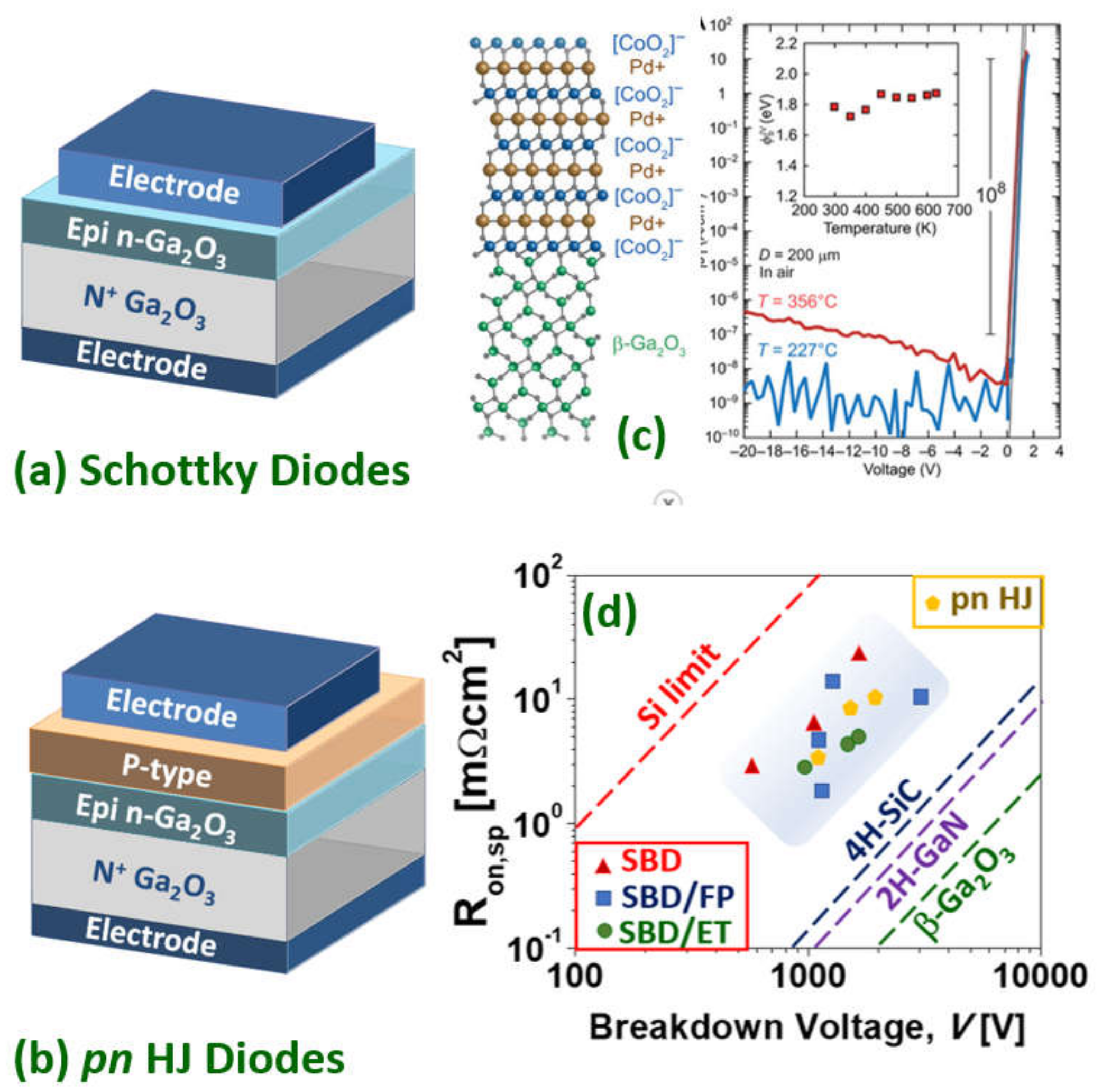
3.4. Gallium Oxide Power Rectifiers

Once the device-grade epitaxial layers have been grown either homo- (bulk Ga2O3) hetero- (e.g., sapphire, silicon), or both, the simplest electronic devices one can define are rectifiers. In a Schottky rectifier, the counter-electrode (cathode) is processed to allow low resistance Ohmic contact while the anode contact is intended as a Schottky junction over a lightly doped epitaxy; it conducts electrons in the forward mode while sustaining large electric fields (by the creation of a depletion space charge region) in the reverse mode. As mentioned previously, devices using Ga2O3 are primarily limited to unipolar devices and Schottky diodes are made, in general, on n-type semiconductor layers as electrons are lighter than holes. However, it is also important to consider the appropriate metal contacts to Ga2O3 as they are responsible for connecting the semiconductor to the surrounding electrical circuit/system and parameters such as the Schottky barrier height are crucial. For different contacts to Ga2O3, such as in GaN and AlGaN, which utilize stacks of different metals [132], this decision can make an important difference to the nature of the contact. Regarding Schottky contacts to Ga2O3,Ni/Au is a common choice (see Table 2). Other Schottky contacts investigated include Pt, Ni, Cu, W, Ir, TiN/Au, Pt/Ti/Au, Ni/Au, ndPt/Au [133,134,135,136]. Very recently, an ultra-large Schottky barrier of ~1.8 eV was extracted for all-oxide PdCoO2/β-Ga2O3 Schottky diodes [137]. The polar layered structure of PdCoO2 generates electric dipoles, realizing a large Schottky barrier height of ~1.8 eV (well beyond the 0.7 eV expected from the basal Schottky–Mott relation) along with a large on/off ratio approaching 108, even at a high temperature of 350 °C (Figure 5c). As there are a number of polar oxides, this is a promising approach to increase the reverse blocking voltage of Ga2O3 diodes [138].
In the counter-electrode, highly doped regions beneath the metallization are deployed to assist ohmicity of the contacts [139]. The dopants for this have previously been discussed. Another approach to this is using thin films of highly-conducting oxides [140].
Ohmic contacts to β-Ga2O3 are commonly based on Ti/Au, however other metal contacts have been utilized, such as In, Ti, Ti/Al/Au, In/Au, and Ti/Al/Ni/Au. Besides, there are other metals which have exhibited pseudo Ohmic behavior including Zr, Ag, and Sn [132]. This pseudo nature meant that, initially, ohmicity was observed but, after annealing, rectifying behavior became dominant. Therefore, the Schottky/Ohmic nature is also dependent upon the Ga2O3′s surface/interface states together with the exact choice of metal stack, explaining, in turn, the varying contact resistivity of certain metals. While delivering low contact resistance, it is worth mentioning that Au is not considered a CMOS-compatible metal. This is an issue shared with GaN-based technology [148].
For the continued development of high voltage β-Ga2O3devices, edge termination is an important aspect as it is with its Si, GaN, and 4H-SiCcounterparts. Edge termination in β-Ga2O3is being explored and focused specifically on field plates (FP), imparted edge termination (ET), guard ring field plates, thermally oxidized termination, beveled mesas, and trench. These techniques are all deployed to further manage the electrical field to reduce the electric field crowding at the diode edges to increase its blocking capabilities. SBD devices can be made with either a vertical architecture, using homoepitaxial Ga2O3 or with a lateral architecture using either homo- or heteroepitaxial (e.g., on sapphire) Ga2O3. In general, the vertical structure is preferred as the device pitch is reduced and the encapsulation is simpler. Hu et al. [141] demonstrated a field-plated lateral β-Ga2O3 SBD on a sapphire substrate with a reverse blocking voltage of more than 3 kV, an Ron of 24.3 mΩcm2 (anode–cathode spacing 24 μm), and an FOM >0.37 GWcm−2 (while an FOM of ~500 GWcm−2 was achieved as the anode-cathode spacing (and Vbr) was reduced). Zhou et al. [149] implemented a Mg implanted ET device on a vertical β-Ga2O3 SBD with a reverse blocking voltage of 1.55 kV and a low specific on-resistance of 5.1 mΩcm2 (epi thickness 10 μm) and an FOM of 0.47 GWcm−2. Analogously, Lin et al. [150] implemented a guard ring with or without an FP on vertical SBDs. The terminated devices exhibited a specific on-resistance of 4.7 mΩcm2 and a Vbr of 1.43 kV. Wang et al. [151] implemented a thermally oxidized termination on a vertical SBD with a Vbr of 940 V, a specific on-resistance of 3.0 mΩcm2, and an FOM of 0.295 GWcm−2. Allen et al. [152] implemented a small-angle beveled field plate (SABFP), on thinned Ga2O3 substrates and a non-punch-through vertical SBD design rendering a Vbr of 1100 V, a peak electric field of 3.5 MVcm−1, and an FOM of 0.6 GWcm−2.
Somehow the state of the art is given by Li et al. [153]. They demonstrated an FP vertical Ga2O3 trench SBDs with a Vbr of 2.89 kV (which is ~500 V higher than those without FPs). The trench SBDs exhibited a differential specific on-resistance of 10.5 (8.8) mΩcm2 from DC (pulsed) measurements leading to an FOM of 0.80 (0.95) GWcm−2. This Baliga’s power FOM is approaching that for the best vertical SBD GaN devices (e.g., 1.7 GWcm−2 [154]) but is still several times smaller than lateral AlGaN/GaN SBD (e.g., 3.6 GWcm−2 [155]) and bipolar p-n vertical GaN diodes (e.g., ~4.6 GWcm−2 [156]). Both, the 2D gas formed at the AlGaN/GaN interface and the bipolar injection are effective ways of further reducing the on-resistance in these devices while keeping the breakdown voltage high. The lack of low resistivity p-type layer for the anode has to date, prevented a competitive homojunction p-n Ga2O3 diode, but p-n heterojunction diodes have been realized by integrating n-type Ga2O3 with p-type semiconductors, such as CuO (1.49 kV) [157] and NiO (1.06 kV/1.86kV) [158,159].Nickel oxide as the p-type blocking layer in heterojunction power diodes resulted in a particularly promising approach with this NiO/Ga2O3device [160] yielding a Baliga’s FOM of 0.33 GWcm−2 (Figure 5c,d).
Recently, extremely high-k dielectrics have been explored for electric field management in WBG semiconductor-based lateral and vertical device structures [160,161,162,163,164]. According to the TCAD simulations of Roy et al. [165], a super-dielectric Ga2O3 SBD with practically achievable device dimensions with extremely high FOM should be possible; e.g., 20kVcanbeachievedforan Ron of 10 mΩ-cm2 with a dielectric constant of 300, a Ga2O3 width/dielectric width ratio of 0.2, and an aspect ratio (drift layer length (anode to cathode spacing)/drift layer width ratio) of 10 resulting in a PFOM of 40 GWcm−2 (surpassing the theoretical unipolar FOM of β-Ga2O3SBD by four times).

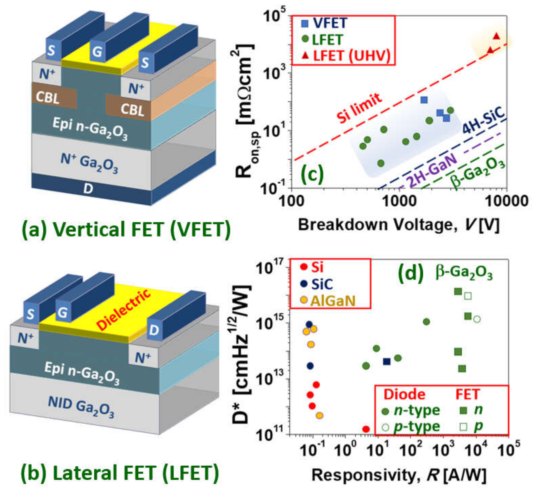
3.5. Gallium Oxide Power Transistors

A power MOSFET fabrication process generally includes a number of technological steps including either gate dielectrics, surface passivation, drain/source ohmic contacts, implant doping, isolation, mesa etch, or in combination. Due to the large bandgap of Ga2O3, the most suitable gate insulators are those with enough (conduction and valence) band-offsets to avoid current injection through the gate (e.g., SiO2 and Al2O3 and perhaps other oxides such as Y2O3, MgO, and Mg2AlO4). While balancing the dielectric constant to achieve more gate capacitance and more carriers in the conductive channel [166]. Defining a contact region by implantation, such as in Si, SiC, and GaN power MOSFET technologies, is a usual choice [167], in Ga2O3 this is typically n+ Si-ion implantation. While other techniques have been suggested to further decrease the contact resistivity, such as formation of surface states [168] or the adoption of a TCO as a metallic interface [169].
As in, the more mature, AlGaN/GaN HEMT technology, Ohmic contacts are typically made with a multilayer metal stack consisting of an adhesion layer (e.g., Ti, Ta), an overlayer (Al), a barrier layer (e.g., Ni, Ti, Mo), and a capping of Au [170,171]. Nevertheless, it has been argued that simpler metal structures, such as Ti/Ga2O3, are also efficient if there is an oxygen deficient Ga2O3 surface [172] (a double charged oxygen vacancy is a well-known intrinsic donor in oxides [107]). Indeed, Yao et al. [132] suggested that the surface states appear to have a more dominant role in the transformation from a Schottky to an Ohmic interface than the choice of metal.
As with power SBDs, power MOSFETs can be defined in a vertical Ga2O3 homoepitaxial structure (typical of SiC power MOSFETs) and lateral structure (typical of AlGaN/GaN power HEMTs) which can be either homoepitaxial or heteroepitaxial (Figure 6). Ga2O3 power MOSFETs are mostly unipolar n-type and operate in depletion mode (D-mode or normally-on) but a number of techniques have been reported to make enhancement mode (E-mode or normally-off) Ga2O3 devices. For example, Chabak et al. [173] reported an enhancement-mode β-Ga2O3 MOSFETs on a Si-doped homoepitaxial channel grown by molecular beam epitaxy and, using a gate recess process to partially remove the epitaxial channel under the 1-μm gated region to fully deplete at zero gate bias. With a breakdown voltage of 505 V (8 mm source-drain spacing), a maximum current density of 40 mA mm−1, and an on/off ratio of 109. Hu et al. [174] achieved (in 2018) a larger blocking voltage (1.075 kV), a larger threshold voltage (1.2–2.2 V), and a larger output current (~500 A cm−2) in a first demonstration of vertical E-mode MOSFET with significatively larger FOM (~80 MW cm−2).
The E-mode was accomplished by doping profiling in a FinFET design (a type of 3D, non-planar transistor which has become the usual layout for the smallest CMOS 14 nm, 10 nm, and 7 nm nodes). This kind of E-mode vertical power device was later optimized to sustain up to a blocking voltage of 1.6kV [175], a threshold voltage of 2.66 kV, a maximum current density of 25.2 mWcm2, and a record FOM of 280 MW cm−2 [176]. Among D-mode devices, the ones reported by Lv et al. [177] stand out for exhibiting a particularly large FOM. They reported (in 2019) [177] source-FP β-Ga2O3 MOSFETs on a Si-doped/Fe-doped semi-insulating β-Ga2O3 substrate exhibiting 222 mA mm−1 (18 mm source-drain spacing) with on-resistance of 11.7 mΩcm2, a Vbr of 680 V and an FOM of 50.4 MWcm−2. Later (in 2020) [178], they adopted a T-shaped gate and source connected FP structure to increase the Vbr up to 1.4 kV/2.9 kV (for 4.8 μm/17.8 μm source-drain spacing), with a specific on-resistances of 7.08 mΩcm2/46.2 mΩcm2. These yielded a record high FOM of 277 MW cm−2, together with negligible gate or drain pulsed current collapse and a drain current on/off ratio of 109.
Other lateral D-mode devices with high FOM were reported by Tetzner et al. [179]. By using sub-μm gate lengths (combined with gate recess) and optimization of compensation-doped high-quality crystals, implantation based inter-device isolation, and SiNx-passivation, breakdown voltages of 1.8 kV and an FOM of 155 MW cm−2 were achieved. In 2020, Sharma et al. [180] reported Ga2O3 lateral D-mode field-plated MOSFETs exhibiting an ultra-high Vbr of 8.03 kV (70 mm) by using polymer SU8 passivation. The current was rather low, however, due to plasma-induced damage of channel and access regions resulting in an impractical FOM of 7.73 kW cm−2 (i.e., not above the silicon limit). As reported by Kalarickal et al. [164], ultra-high-k ferroelectric dielectrics, such as BaTiO3, can, in principle, provide an efficient field management strategy by improving the uniformity of electric field profile in the gate-drain region of lateral FETs. High average breakdown fields of 1.5 MV/cm (918 V) and 4 MVcm−1 (201 V) were demonstrated for gate-drain spacings of 6μm and 0.6 μm, respectively, in 𝛽-Ga2O3, at a high channel sheet charge density of 1.8×1013 cm−2. An elevated sheet charge density together with a high breakdown field enabled a record power FOM of 376 MWcm−2 at a gate-drain spacing of 3 μm (Figure 6c). As in the case of SBDs, these performances for the Ga2O3 devices are already impressive and well beyond the silicon limit but still lag behind the best (much more mature) GaN devices in their respective power ratings [181,182].
All the above power MOSFET devices are unipolar n-type. These devices are sometimes referred as MISFETs so as to distinguish them from the conventional p-n junction based MOSFETs, since there are no p-regions in these MISFETs [175]. As mentioned in the previous sections, there are, however, several reports of p-type Ga2O3in nominally undoped, H-doped and N-doped β-Ga2O3. In particular, Wuetal. [131] proposed a growth mechanism of multistep structural phase transitions from hexagonal P63mc GaN to rhombohedral R3c α-GaNxO3(1−x)/2,and finally to monolithic C2/m N-doped β-Ga2O3. This improves the crystalline quality, facilitates acceptor doping, increases the acceptor activation efficiency, and thus enhances the p-type conductivity (acceptor ionization energy of 0.165 eV, Hall resistivity of 17.0 Ωcm, Hall hole mobility of 23.6 cm2V−1s−1, hole concentration of 1.56×1016 cm−3). P-type β-Ga2O3 films-based lateral MOSFET deep-ultraviolet (DUV) PDs were fabricated with extremely high responsivity (5.1×10³ A/W) and detectivity (1.0×10¹⁶Jones) under 250 nm light illumination (40 μW/cm2) conditions. Figure 6d shows the responsivity and detectivity (D*) for state-of-the-art DUV PDs based on various WBG materials (adapted from [131]), in which it can be seen how β-Ga2O3 surpasses conventional Si-, SiC-, and AlGaN-based devices in terms of responsivity and detectivity.

4. Other Emerging Oxide Semiconductors for Power Electronics

Ga2O3phase engineering: Owing to the nonpolar nature of β-Ga2O3 crystals, modulation-doped heterostructure is one of the possible approaches to realize Ga2O3-based FETs [183]. Analogously, p-type semiconductors (e.g., p-type nitrides such as GaN) may be introduced to yield normally-off β-Ga2O3 field-effect transistors with tunable positive threshold voltages [184]. Other phases of Ga2O3 have also received attention due to potentially favorable growth characteristics, and to the possibility of polarization engineering made possible by the polar nature of their crystal structures. In principle, this polarization could be utilized to produce Ga2O3 two-dimensional electron gases (2DEGs) in analogy with GaN/AlN-based transistors [185].
Ga2O3alloy engineering: The aluminum gallium oxide, AlxGa1-xO3, is a ternary alloy of Al2O3 and Ga2O3. It was already noted by Roy [186] in 1952 that the gallium ion closely resembles the aluminum ion and substitutes for it in several structures. Because β-(AlGa)2O3 is not the energetically favored crystalline phase for large Al compositions, the crystal converts to competing structural phases when grown on β-Ga2O3 substrates [187]. Thus, it has been difficult to obtain gallium oxide UWBG materials exceeding the bandgap of ~6 eV which is available to the materials in the nitride family in AlN. Very recently however, it was found that single-crystalline layers of α-(AlGa)2O3 alloys spanning bandgaps of 5.4–8.6 eV can be grown by molecular beam epitaxy [188]. By varying the alloy composition, bandgap energies from ~5.4 up to 8.6 eV with a bowing parameter of 1.1 eV are achieved, making α-(AlxGa1−x)2O3 the largest bandgap epitaxial material family to date. If these layers can be controllably doped, it would pave the way for α-(AlxGa1−x)2O3–based high-power heterostructure electronic and photonic devices at bandgaps far beyond all materials available today [189].
Spinel electronics: The spinel zinc gallate, ZnGa2O4, is a nearly stoichiometric mixed oxide made of Ga2O3 and ZnO.A potential advantage of spinel ZnGa2O4 is its great dopability prospects owing to the spinel‘s inherent diversity in cation coordination possibilities [106]. Normal spinels have all A cations in the tetrahedral site and all B cations in the octahedral site, e.g., Zn-tetrahedral site Zn2+(Td) and Ga-octahedral site Ga3+(Oh), so that normal ZnGa2O4 is Zn(2+[Td])Ga2(3+[Oh])O4(2−). The spinel’s off-stoichiometry, from the ideal 1:2:4 proportions, or the creation of cation antisite defects are known routes for doping these compounds. Dominant defects in spinels are antisite donors (e.g., ZnGa) or donor-like Ga3+(Oh)-on-Td and antisite acceptors (e.g., GaZn) with acceptor-like Zn2+(Td)-on-Oh antisite defects resulting in an intrinsic bipolar power semiconductor [190]. ZnGa2O4 is therefore a potential outstanding UWBG (~5 eV) oxide semiconductor but is only one among the many possible spinel oxides. There are over 1000 compounds that are known to crystalize in the spinel structure. The sub-family of spinel oxides is a large and important class of multi-functional oxide semiconductors with many optoelectronics applications in areas such as batteries, fuel cells, catalysis, photonics (phosphors, bio-imaging, photodetectors), spintronics (magnets, bio-magnets), or thermoelectricity [191]. Other magnesium-based Ga-spinels, such as MgGa2O4and Zn1-xMgxGa2O4, are related oxides that are currently being investigated [192,193].

5. Conclusions

The rational use of electrical energy and information are central themes in the greatest climatic challenge of the 21st century. UWBG oxides, such as Ga2O3 and related materials, are promising power electronic candidates since their critical electric field is large compared to beyond silicon WBG (i.e., SiC and GaN), while still yielding a moderate mobility, high quality epi-layers, and large bulk single crystals (more than 6-inch) using low cost and scalable fabrication approaches. During the last decade, the Ga2O3 power diode and transistor progress has been impressive, with devices now approaching the frontier of the field. The material system also opens new optoelectronics avenues (owing its UVC spanning bandgap), and new electronics perspectives based on stabile interfaces and a natural integration with extremely high-k functional oxides. The advances offered by Ga2O3 are also opening the door to many more UWBG oxides (the largest family of wide bandgap semiconductors), such as the spinel, ZnGa2O4, along with many more that are anticipated. Therefore, the ever-increasing family of UWBG oxides is at the very frontier of a more efficient energy electronics which is adapted to tackle the 21st century climatic targets, although there still is a lot of room for performance improvements, technical innovation, and new discoveries.

Author Contributions

Conceptualization A.P.-T., E.C., M.R.J.; writing—original draft preparation, A.P.-T., Z.C., J.J.A.; writing—review and editing, A.P.-T., Z.C., J.J.A.; visualization, A.P.-T.; supervision, A.P.-T.; project administration, A.P.-T.; funding acquisition, E.C., A.P.-T., M.R.J. All authors have read and agreed to the published version of the manuscript.

Funding

This research was funded by the French National Research Agency ANR, “Accelerating the demonstration of Gallium Oxide’s outstanding potential for Energy application” (GOPOWER), grant number Project-ANR-21-CE50-0015.

Institutional Review Board Statement

Not applicable.

Informed Consent Statement

Not applicable.

Data Availability Statement

Not applicable.

Acknowledgments

Authors acknowledge IRP -”GALLIA”, CNRS, France. The ICN2 is funded by the CERCA programme/Generalitat de Catalunya. The ICN2 is supported by the Severo Ochoa Centres of Excellence programme, funded by the Spanish Research Agency (AEI, grant no. SEV-2017-0706).

Conflicts of Interest

The authors declare no conflict of interest.

References

  1. IPCC Working Group I Report, Climate Change 2021: The Physical Science Basis. Available online: www.ipcc.ch (accessed on 9 August 2021).
  2. US Environmental Protection Agency (EPA). Greenhouse Gas Emissions: Global Greenhouse Gas Emissions Data. 2021. Available online: https://www.epa.gov/ghgemissions/global-greenhouse-gas-emissions-data (accessed on 6 November 2017).
  3. Leo Lorenz, Power Device Development Trends—From Silicon to Wide Bandgap? Available online: www.power-and-beyond.com (accessed on 16 December 2021).
  4. Pearton, S.J.; Ren, F.; Tadjer, M.; Kim, J. Perspective: Ga2O3 for ultra-high power rectifiers and MOSFETS. J. Appl. Phys. 2018, 124, 220901. [Google Scholar] [CrossRef] [Green Version]
  5. Reese, S.B.; Remo, T.; Green, J.; Zakutayev, A. How Much Will Gallium Oxide Power Electronics Cost? Joule 2019, 3, 903–907. [Google Scholar] [CrossRef] [Green Version]
  6. Chu, S.; Cui, Y.; Liu, N. The path towards sustainable energy. Nat. Mater. 2017, 16, 16–22. [Google Scholar] [CrossRef] [PubMed]
  7. Millan, J.; Godignon, P.; Perpiñà, X.; Perez-Tomas, A.; Rebollo, J. A Survey of Wide Bandgap Power Semiconductor Devices. IEEE Trans. Power Electron. 2013, 29, 2155–2163. [Google Scholar] [CrossRef]
  8. Spaziani, L.; Lu, L. Silicon, GaN and SiC: There’s room for all: An application space overview of device considerations. In Proceedings of the 2018 IEEE 30th International Symposium on Power Semiconductor Devices and ICs (ISPSD), Chicago, IL, USA, 13–17 May 2018; pp. 8–11. [Google Scholar]
  9. Jones, E.A.; Wang, F.F.; Costinett, D. Review of Commercial GaN Power Devices and GaN-Based Converter Design Challenges. IEEE J. Emerg. Sel. Top. Power Electron. 2016, 4, 707–719. [Google Scholar] [CrossRef]
  10. Tsao, J.Y.; Chowdhury, S.; Hollis, M.A.; Jena, D.; Johnson, N.M.; Jones, K.A.; Kaplar, R.J.; Rajan, S.; Van de Walle, C.G.; Bellotti, E.; et al. Ultrawide-Bandgap Semiconductors: Research Opportunities and Challenges. Adv. Electron. Mater. 2017, 4, 1600501. [Google Scholar] [CrossRef] [Green Version]
  11. Perez-Tomas, A.; Teherani, F.H.; Bove, P.; Sandana, E.V.; Chikoidze, E.; Jennings, M.R.; Rogers, D.J.; Russell, S.A.O. Wide and ultra-wide bandgap oxides: Where paradigm-shift photovoltaics meets transparent power electronics. In Proceedings of the SPIE 10533, Oxide-Based Materials and Devices IX, San Francisco, CA, USA, 27 January–1 February 2018. [Google Scholar] [CrossRef] [Green Version]
  12. Perez-Tomas, A.; Chikoidze, E.; Rogers, D.J. A walk on the frontier of energy electronics with power ultra-wide bandgap oxides and ultra-thin neuromorphic 2D materials. In Proceedings of the SPIE 11687, Oxide-Based Materials and Devices XII, San Francisco, CA, USA, 6–12 March 2021. [Google Scholar] [CrossRef]
  13. Perez-Tomas, A.; Lodzinski, M.; Guy, O.J.; Jennings, M.R.; Placidi, M.; Llobet, J.; Gammon, P.M.; Davis, M.C.; Covington, J.A.; Burrows, S.E.; et al. Si/SiC bonded wafer: A route to carbon free SiO2 on SiC. Appl. Phys. Lett. 2009, 94, 103510. [Google Scholar] [CrossRef] [Green Version]
  14. Nawaz, M. Introductory Chapter: Earth Crust-Origin, Structure, Composition and Evolution. In Earth Crust; IntechOpen: London, UK, 2019. [Google Scholar] [CrossRef] [Green Version]
  15. Jackson, I. The Earth’s Mantle—Composition, Structure and Evolution; Cambridge University Press: Cambridge, UK, 1998. [Google Scholar]
  16. Higashiwaki, M.; Sasaki, K.; Murakami, H.; Kumagai, Y.; Koukitu, A.; Kuramata, A.; Masui, T.; Yamakoshi, S. Recent progress in Ga2O3 power devices. Semicond. Sci. Technol. 2016, 31, 034001. [Google Scholar] [CrossRef]
  17. Kuramata, A.; Koshi, K.; Watanabe, S.; Yamaoka, Y.; Masui, T.; Yamakoshi, S. Bulk crystal growth of Ga2O3. In Proceedings of the SPIE 10533, Oxide-Based Materials and Devices IX, San Francisco, CA, USA, 27 January–1 February 2018. [Google Scholar] [CrossRef]
  18. Playford, H.Y.; Hannon, A.C.; Barney, E.R.; Walton, R.I. Structures of Uncharacterised Polymorphs of Gallium Oxide from Total Neutron Diffraction. Chem. A Eur. J. 2013, 19, 2803–2813. [Google Scholar] [CrossRef]
  19. Geller, S. Crystal Structure of β—Ga2O3. J. Chem. Phys. 1960, 33, 676–684. [Google Scholar] [CrossRef]
  20. Blasse, G.; Bril, A. Some observations on the luminescence of β-Ga2O3. J. Phys. Chem. Solids 1970, 31, 707–711. [Google Scholar] [CrossRef]
  21. Lorenz, M.; Woods, J.; Gambino, R. Some electrical properties of the semiconductor β Ga2O3. J. Phys. Chem. Solids 1967, 28, 403–404. [Google Scholar] [CrossRef]
  22. Tippins, H.H. Optical Absorption and Photoconductivity in the Band Edge of β−Ga2O3. Phys. Rev. 1965, 140, A316–A319. [Google Scholar] [CrossRef]
  23. Nouketcha, F.L.L.; Cui, Y.; Lelis, A.; Green, R.; Darmody, C.; Schuster, J.; Goldsman, N. Investigation of Wide- and Ultrawide-Bandgap Semiconductors From Impact-Ionization Coefficients. IEEE Trans. Electron. Devices 2020, 67, 3999–4005. [Google Scholar] [CrossRef]
  24. Chikoidze, E.; Tchelidze, T.; Sartel, C.; Chi, Z.; Kabouche, R.; Madaci, I.; Rubio, C.; Mohamed, H.; Sallet, V.; Medjdoub, F.; et al. Ultra-high critical electric field of 13.2 MV/cm for Zn-doped p-type β-Ga2O3. Mater. Today Phys. 2020, 15, 100263. [Google Scholar] [CrossRef]
  25. Baliga, B. Power semiconductor device figure of merit for high-frequency applications. IEEE Electron Device Lett. 1989, 10, 455–457. [Google Scholar] [CrossRef]
  26. Ma, N.; Tanen, N.; Verma, A.; Guo, Z.; Luo, T.; Xing, H.; Jena, D. Intrinsicelectronmobilitylimits in β-Ga2O3. Appl. Phys. Lett. 2016, 109, 212101. [Google Scholar] [CrossRef] [Green Version]
  27. Fu, B.; Jia, Z.; Mu, W.; Yin, Y.; Zhang, J.; Tao, X. A review of β-Ga2O3 single crystal defects, their effects on device performance and their formation mechanism. J. Semicond. 2019, 40, 011804. [Google Scholar] [CrossRef]
  28. Stuchlikova, T.H.; Stuchlik, J.; Remes, Z.; Taylor, A.; Mortet, V.; Ashcheulov, P.; Gregora, I.; Krivyakin, G.; Volodin, V. High-Temperature PIN Diodes Based on Amorphous Hydrogenated Silicon-Carbon Alloys and Boron-Doped Diamond Thin Films. Phys. Status Solidi 2020, 257, 1900247. [Google Scholar] [CrossRef]
  29. Chase, A.O. Growth of beta-Ga2, O3 by the Verneuil Technique. J. Am. Ceram. Soc. 1964, 47, 470. [Google Scholar] [CrossRef]
  30. Galazka, Z.; Ganschow, S.; Irmscher, K.; Klimm, D.; Albrecht, M.; Schewski, R.; Pietsch, M.; Schulz, T.; Dittmar, A.; Kwasniewski, A.; et al. Bulk single crystals of β-Ga2O3 and Ga-based spinels as ultra-wide bandgap transparent semiconducting oxides. Prog. Cryst. Growth Charact. Mater. 2020, 67, 100511. [Google Scholar] [CrossRef]
  31. Galazka, Z.; Irmscher, K.; Schewski, R.; Hanke, I.M.; Pietsch, M.; Ganschow, S.; Klimm, D.; Dittmar, A.; Fiedler, A.; Schroeder, T.; et al. Czochralski-grown bulk β-Ga2O3 single crystals doped with mono-, di-, tri-, and tetravalent ions. J. Cryst. Growth 2019, 529, 125297. [Google Scholar] [CrossRef]
  32. Galazka, Z.; Schewski, R.; Irmscher, K.; Drozdowski, W.; Witkowski, M.E.; Makowski, M.; Wojtowicz, A.J.; Hanke, I.M.; Pietsch, M.; Schulz, T.; et al. Bulk β-Ga2O3 single crystals doped with Ce, Ce+Si, Ce+Al, and Ce+Al+Si for detection of nuclear radiation. J. Alloys Compd. 2019, 818, 152842. [Google Scholar] [CrossRef]
  33. Irmscher, K.; Galazka, Z.; Pietsch, M.; Uecker, R.; Fornari, R. Electrical properties of β-Ga2O3 single crystals grown by the Czochralski method. J. Appl. Phys. 2011, 110, 063720. [Google Scholar] [CrossRef]
  34. Víllora, E.G.; Shimamura, K.; Yoshikawa, Y.; Aoki, K.; Ichinose, N. Large-size β-Ga2O3 single crystals and wafers. J. Cryst. Growth 2004, 270, 420–426. [Google Scholar] [CrossRef]
  35. Hoshikawa, K.; Kobayashi, T.; Matsuki, Y.; Ohba, E. 2-inch diameter (1 0 0) β-Ga2O3 crystal growth by the vertical Bridgman technique in a resistance heating furnace in ambient air. J. Cryst. Growth 2020, 545, 125724. [Google Scholar] [CrossRef]
  36. Hoshikawa, K.; Ohba, E.; Kobayashi, T.; Yanagisawa, J.; Miyagawa, C.; Nakamura, Y. Growth of β-Ga2O3 single crystals using vertical Bridgman method in ambient air. J. Cryst. Growth 2016, 447, 36–41. [Google Scholar] [CrossRef]
  37. Harwig, T.; Schoonman, J. Electrical properties of β-Ga2O3 single crystals. II. J. Solid State Chem. 1978, 23, 205–211. [Google Scholar] [CrossRef]
  38. Cui, H.; Mohamed, H.; Xia, C.; Sai, Q.; Zhou, W.; Qi, H.; Zhao, J.; Si, J.; Ji, X. Tuning electrical conductivity of β-Ga2O3 single crystals by Ta doping. J. Alloys Compd. 2019, 788, 925–928. [Google Scholar] [CrossRef]
  39. Hossain, E.; Kulkarni, R.; Mondal, R.; Guddolian, S.; Rahman, A.A.; Thamizhavel, A.; Bhattacharya, A. Optimization of Gas Ambient for High Quality β-Ga2O3 Single Crystals Grown by the Optical Floating Zone Technique. ECS J. Solid State Sci. Technol. 2019, 8, Q3144–Q3148. [Google Scholar] [CrossRef]
  40. Suzuki, N.; Ohira, S.; Tanaka, M.; Sugawara, T.; Nakajima, K.; Shishido, T. Fabrication and characterization of transparent conductive Sn-doped β-Ga2O3 single crystal. Phys. Status Solidi 2007, 4, 2310–2313. [Google Scholar] [CrossRef]
  41. Tomioka, Y.; Ozaki, Y.; Inaba, H.; Ito, T. Compensation effects between impurity cations in single crystals of a wide gap semiconductor β-Ga2O3 prepared by the floating zone method. Jpn. J. Appl. Phys. 2019, 58, 091009. [Google Scholar] [CrossRef]
  42. Zhou, W.; Xia, C.; Sai, Q.; Zhang, H. Controlling n-type conductivity of β-Ga2O3 by Nb doping. Appl. Phys. Lett. 2017, 111, 242103. [Google Scholar] [CrossRef]
  43. Galazka, Z. β-Ga2O3 for wide-bandgap electronics and optoelectronics. Semicond. Sci. Technol. 2018, 33, 113001. [Google Scholar] [CrossRef]
  44. Galazka, Z.; Uecker, R.; Klimm, D.; Irmscher, K.; Naumann, M.; Pietsch, M.; Kwasniewski, A.; Bertram, R.; Ganschow, S.; Bickermann, M. Scaling-Up of Bulk β-Ga2O3Single Crystals by the Czochralski Method. ECS J. Solid State Sci. Technol. 2016, 6, Q3007–Q3011. [Google Scholar] [CrossRef]
  45. Saleh, M.; Varley, J.B.; Jesenovec, J.; Bhattacharyya, A.; Krishnamoorthy, S.; Swain, S.; Lynn, K.G. Degenerate doping in β-Ga2O3 single crystals through Hf-doping. Semicond. Sci. Technol. 2020, 35, 04LT01. [Google Scholar] [CrossRef] [Green Version]
  46. Kuramata, A.; Koshi, K.; Watanabe, S.; Yamaoka, Y.; Masui, T.; Yamakoshi, S. High-quality β-Ga2O3single crystals grown by edge-defined film-fed growth. Jpn. J. Appl. Phys. 2016, 55, 1202A2. [Google Scholar] [CrossRef]
  47. Yao, Y.; Sugawara, Y.; Ishikawa, Y. Identification of Burgers vectors of dislocations in monoclinic β-Ga2O3 via synchrotron X-ray topography. J. Appl. Phys. 2020, 127, 205110. [Google Scholar] [CrossRef]
  48. Hoshikawa, K.; Kobayashi, T.; Ohba, E. 50 mm diameter Sn-doped (0 0 1) β-Ga2O3 crystal growth using the vertical Bridgeman technique in ambient air. J. Cryst. Growth 2020, 546, 125778. [Google Scholar] [CrossRef]
  49. Aubay, E.; Gourier, D. Magnetic bistability and Overhauser shift of conduction electrons in gallium oxide. Phys. Rev. B 1993, 47, 15023–15036. [Google Scholar] [CrossRef]
  50. He, N.; Tang, H.; Liu, B.; Zhu, Z.; Li, Q.; Guo, C.; Gu, M.; Xu, J.; Liu, J.; Xu, M.; et al. Ultra-fast scintillation properties of β-Ga2O3 single crystals grown by Floating Zone method. Nucl. Instrum. Methods Phys. Res. Sect. A Accel. Spectrom. Detect. Assoc. Equip. 2018, 888, 9–12. [Google Scholar] [CrossRef]
  51. Usui, Y.; Oya, T.; Okada, G.; Kawaguchi, N.; Yanagida, T. Comparative study of scintillation and optical properties of Ga2O3 doped with ns2 ions. Mater. Res. Bull. 2017, 90, 266–272. [Google Scholar] [CrossRef]
  52. Yanagida, T.; Kawaguchi, N. Optical and scintillation properties of alkaline earth doped Ga2O3 single crystals prepared by the floating zone method. Jpn. J. Appl. Phys. 2019, 59, SCCB20. [Google Scholar] [CrossRef]
  53. Zhang, S.; Lian, X.; Ma, Y.; Liu, W.; Zhang, Y.; Xu, Y.; Cheng, H. Growth and characterization of 2-inch high quality β-Ga2O3 single crystals grown by EFG method. J. Semicond. 2018, 39, 083003. [Google Scholar] [CrossRef]
  54. Oshima, T.; Hashiguchi, A.; Moribayashi, T.; Koshi, K.; Sasaki, K.; Kuramata, A.; Ueda, O.; Oishi, T.; Kasu, M. Electrical properties of Schottky barrier diodes fabricated on (001) β-Ga2O3substrates with crystal defects. Jpn. J. Appl. Phys. 2017, 56, 86501. [Google Scholar] [CrossRef]
  55. Oshima, Y.; Vίllora, E.G.; Shimamura, K. Quasi-heteroepitaxial growth of β-Ga2O3 on off-angled sapphire (0 0 0 1) substrates by halide vapor phase epitaxy. J. Cryst. Growth 2015, 410, 53–58. [Google Scholar] [CrossRef]
  56. Xiong, Z.-N.; Xiu, X.-Q.; Li, Y.-W.; Hua, X.-M.; Xie, Z.-L.; Chen, P.; Liu, B.; Han, P.; Zhang, R.; Zheng, Y.-D. Growth of β -Ga2O3 Films on Sapphire by Hydride Vapor Phase Epitaxy. Chin. Phys. Lett. 2018, 35, 058101. [Google Scholar] [CrossRef]
  57. Yao, Y.; Lyle, L.A.M.; Rokholt, J.A.; Okur, S.; Tompa, G.S.; Salagaj, T.; Sbrockey, N.; Davis, R.F.; Porter, L.M. (Invited) Growth and Characterization of α-,β-, andε-Ga2O3 Epitaxial Layers on Sapphire. ECS Trans. 2017, 80, 191–196. [Google Scholar] [CrossRef]
  58. Xiu, X.; Zhang, L.; Li, Y.; Xiong, Z.; Zhang, R.; Zheng, Y. Application of halide vapor phase epitaxy for the growth of ultra-wide band gap Ga2O3. J. Semicond. 2019, 40, 011805. [Google Scholar] [CrossRef]
  59. Modak, S.; Chernyak, L.; Khodorov, S.; Lubomirsky, I.; Yang, J.; Ren, F.; Pearton, S.J. Impact of Electron Injection and Temperature on Minority Carrier Transport in Alpha-Irradiated ß-Ga2O3 Schottky Rectifiers. ECS J. Solid State Sci. Technol. 2019, 8, Q3050–Q3053. [Google Scholar] [CrossRef] [Green Version]
  60. De Santi, C.; Nardo, A.; Wong, M.; Goto, K.; Kuramata, A.; Yamakoshi, S.; Murakami, H.; Kumagai, Y.; Higashiwaki, M.; Meneghesso, G.; et al. Stability and degradation of isolation and surface in Ga2O3 devices. Microelectron. Reliab. 2019, 100–101, 113453. [Google Scholar] [CrossRef]
  61. Leach, J.H.; Udwary, K.; Rumsey, J.; Dodson, G.; Splawn, H.; Evans, K.R. Halide vapor phase epitaxial growth of β-Ga2O3 and α-Ga2O3 films. APL Mater. 2019, 7, 022504. [Google Scholar] [CrossRef] [Green Version]
  62. Murakami, H.; Nomura, K.; Goto, K.; Sasaki, K.; Kawara, K.; Thieu, Q.T.; Togashi, R.; Kumagai, Y.; Higashiwaki, M.; Kuramata, A.; et al. Homoepitaxial growth of β-Ga2O3layers by halide vapor phase epitaxy. Appl. Phys. Express 2014, 8, 015503. [Google Scholar] [CrossRef]
  63. Bin Anooz, S.; Grüneberg, R.; Wouters, C.; Schewski, R.; Albrecht, M.; Fiedler, A.; Irmscher, K.; Galazka, Z.; Miller, W.; Wagner, G.; et al. Step flow growth of β-Ga2O3 thin films on vicinal (100) β-Ga2O3 substrates grown by MOVPE. Appl. Phys. Lett. 2020, 116, 182106. [Google Scholar] [CrossRef]
  64. Bin Anooz, S.; Grüneberg, R.; Chou, T.-S.; Fiedler, A.; Irmscher, K.; Wouters, C.; Schewski, R.; Albrecht, M.; Galazka, Z.; Miller, W.; et al. Impact of chamber pressure and Si-doping on the surface morphology and electrical properties of homoepitaxial (100) β-Ga2O3 thin films grown by MOVPE. J. Phys. D Appl. Phys. 2020, 54, 034003. [Google Scholar] [CrossRef]
  65. Gogova, D.; Schmidbauer, M.; Kwasniewski, A. Homo- and heteroepitaxial growth of Sn-doped β-Ga2O3 layers by MOVPE. CrystEngComm 2015, 17, 6744–6752. [Google Scholar] [CrossRef]
  66. Albrecht, M.; Schewski, R.; Wouters, C.; Fielder, A.; Irmscher, K.; Galazka, Z.; Popp, A.; Anooz, S.B.; Baldini, M.; Wagner, G. Ga2O3 from Materials to Devices. Appl. Phys. Res. 2021, 5, 011301. [Google Scholar]
  67. Baldini, M.; Albrecht, M.; Fiedler, A.; Irmscher, K.; Schewski, R.; Wagner, G. Editors’ Choice—Si- and Sn-Doped Homoepitaxial β-Ga2O3 Layers Grown by MOVPE on (010)-Oriented Substrates. ECS J. Solid State Sci. Technol. 2016, 6, Q3040–Q3044. [Google Scholar] [CrossRef]
  68. Cui, R.-R.; Zhang, J.; Luo, Z.-J.; Guo, X.; Ding, Z.; Deng, C.-Y. Microstructure, optical, and photoluminescence properties of β-Ga2O3 films prepared by pulsed laser deposition under different oxygen partial pressures. Chin. Phys. B 2021, 30, 028505. [Google Scholar] [CrossRef]
  69. Leedy, K.; Chabak, K.D.; Vasilyev, V.; Look, D.C.; Boeckl, J.J.; Brown, J.L.; Tetlak, S.E.; Green, A.J.; Moser, N.A.; Crespo, A.; et al. Highly conductive homoepitaxial Si-doped Ga2O3 films on (010) β-Ga2O3 by pulsed laser deposition. Appl. Phys. Lett. 2017, 111, 012103. [Google Scholar] [CrossRef]
  70. Shen, H.; Baskaran, K.; Yin, Y.; Tian, K.; Duan, L.; Zhao, X.; Tiwari, A. Effect of thickness on the performance of solar blind photodetectors fabricated using PLD grown β-Ga2O3 thin films. J. Alloys Compd. 2019, 822, 153419. [Google Scholar] [CrossRef]
  71. Vu, T.K.O.; Lee, D.U.; Kim, E.K. The effect of oxygen partial pressure on band gap modulation of Ga2O3 grown by pulsed laser deposition. J. Alloys Compd. 2019, 806, 874–880. [Google Scholar] [CrossRef]
  72. Pearton, S.J.; Yang, J.; Cary, P.H., IV; Ren, F.; Kim, J.; Tadjer, M.J.; Mastro, M.A. A review of Ga2O3 materials, processing, and devices. Appl. Phys. Rev. 2018, 5, 011301. [Google Scholar] [CrossRef] [Green Version]
  73. Chen, Z.; Wang, X.; Zhang, F.; Noda, S.; Saito, K.; Tanaka, T.; Nishio, M.; Guo, Q. Temperature dependence of luminescence spectra in europium doped Ga2O3 film. J. Lumin. 2016, 177, 48–53. [Google Scholar] [CrossRef]
  74. Wang, Q.; Chen, J.; Huang, P.; Li, M.; Lu, Y.; Homewood, K.P.; Chang, G.; Chen, H.; He, Y. Influence of growth temperature on the characteristics of β-Ga2O3 epitaxial films and related solar-blind photodetectors. Appl. Surf. Sci. 2019, 489, 101–109. [Google Scholar] [CrossRef]
  75. Yadav, M.K.; Mondal, A.; Das, S.; Sharma, S.; Bag, A. Impact of annealing temperature on band-alignment of PLD grown Ga2O3/Si (100) heterointerface. J. Alloys Compd. 2019, 819, 153052. [Google Scholar] [CrossRef]
  76. Yu, J.; Nie, Z.; Dong, L.; Yuan, L.; Li, D.; Huang, Y.; Zhang, L.; Zhang, Y.; Jia, R. Influence of annealing temperature on structure and photoelectrical performance of β-Ga2O3/4H-SiC heterojunction photodetectors. J. Alloys Compd. 2019, 798, 458–466. [Google Scholar] [CrossRef]
  77. Puurunen, R.L. A Short History of Atomic Layer Deposition: Tuomo Suntola’s Atomic Layer Epitaxy. Chem. Vap. Depos. 2014, 20, 332–344. [Google Scholar] [CrossRef] [Green Version]
  78. Siah, S.C.; Brandt, R.E.; Lim, K.; Schelhas, L.T.; Jaramillo, R.; Heinemann, M.D.; Chua, D.; Wright, J.; Perkins, J.D.; Segre, C.U.; et al. Dopant activation in Sn-doped Ga2O3 investigated by X-ray absorption spectroscopy. Appl. Phys. Lett. 2015, 107, 252103. [Google Scholar] [CrossRef] [Green Version]
  79. Choi, D.-W.; Chung, K.-B.; Park, J.-S. Low temperature Ga2O3 atomic layer deposition using gallium tri-isopropoxide and water. Thin Solid Films 2013, 546, 31–34. [Google Scholar] [CrossRef]
  80. Mizutani, F.; Higashi, S.; Inoue, M.; Nabatame, T. Atomic layer deposition of high purity Ga2O3 films using liquid pentamethylcyclopentadienyl gallium and combinations of H2O and O2 plasma. J. Vac. Sci. Technol. A 2020, 38, 022412. [Google Scholar] [CrossRef]
  81. Ilhom, S.; Mohammad, A.; Shukla, D.; Grasso, J.; Willis, B.G.; Okyay, A.K.; Biyikli, N. Low-Temperature As-Grown Crystalline β-Ga2O3 Films via Plasma-Enhanced Atomic Layer Deposition. ACS Appl. Mater. Interfaces 2021, 13, 8538–8551. [Google Scholar] [CrossRef]
  82. Jiao, Y.; Jiang, Q.; Meng, J.; Zhao, J.; Yin, Z.; Gao, H.; Zhang, J.; Deng, J.; Zhang, X. Growth and characteristics of β-Ga2O3 thin films on sapphire (0001) by low pressure chemical vapour deposition. Vacuum 2021, 189, 110253. [Google Scholar] [CrossRef]
  83. Tao, J.; Lu, H.-L.; Gu, Y.; Ma, H.-P.; Li, X.; Chen, J.-X.; Liu, W.-J.; Zhang, H.; Feng, J.-J. Investigation of growth characteristics, compositions, and properties of atomic layer deposited amorphous Zn-doped Ga2O3 films. Appl. Surf. Sci. 2019, 476, 733–740. [Google Scholar] [CrossRef]
  84. Sasaki, K.; Higashiwaki, M.; Kuramata, A.; Masui, T.; Yamakoshi, S. MBE grown Ga2O3 and its power device applications. J. Cryst. Growth 2013, 378, 591–595. [Google Scholar] [CrossRef]
  85. Mazzolini, P.; Falkenstein, A.; Wouters, C.; Schewski, R.; Markurt, T.; Galazka, Z.; Martin, M.; Albrecht, M.; Bierwagen, O. Substrate-orientation dependence of β-Ga2O3 (100), (010), (001), and (2¯01) homoepitaxy by indium-mediated metal-exchange catalyzed molecular beam epitaxy (MEXCAT-MBE). APL Mater. 2020, 8, 011107. [Google Scholar] [CrossRef] [Green Version]
  86. Nepal, N.; Katzer, D.S.; Downey, B.P.; Wheeler, V.D.; Nyakiti, L.O.; Storm, D.F.; Hardy, M.T.; Freitas, J.A.; Jin, E.N.; Vaca, D.; et al. Heteroepitaxial growth of β-Ga2O3 films on SiC via molecular beam epitaxy. J. Vac. Sci. Technol. A Vac. Surf. Films 2020, 38, 063406. [Google Scholar] [CrossRef]
  87. Kamimura, T.; Nakata, Y.; Higashiwaki, M. Effect of (AlGa)2O3 back barrier on device characteristics of β-Ga2O3 metal-oxide-semiconductor field-effect transistors with Si-implanted channel. Jpn. J. Appl. Phys. 2021, 60, 030906. [Google Scholar] [CrossRef]
  88. Mazzolini, P.; Vogt, P.; Schewski, R.; Wouters, C.; Albrecht, M.; Bierwagen, O. Faceting and metal-exchange catalysis in (010) β-Ga2O3 thin films homoepitaxially grown by plasma-assisted molecular beam epitaxy. APL Mater. 2019, 7, 022511. [Google Scholar] [CrossRef] [Green Version]
  89. Ngo, T.S.; Le, D.D.; Lee, J.; Hong, S.-K.; Ha, J.-S.; Lee, W.-S.; Moon, Y.-B. Investigation of defect structure in homoepitaxial (2¯01) β-Ga2O3 layers prepared by plasma-assisted molecular beam epitaxy. J. Alloys Compd. 2020, 834, 155027. [Google Scholar] [CrossRef]
  90. Ahmadi, E.; Koksaldi, O.S.; Kaun, S.W.; Oshima, Y.; Short, D.B.; Mishra, U.K.; Speck, J.S. Ge doping of β-Ga2O3 films grown by plasma-assisted molecular beam epitaxy. Appl. Phys. Express 2017, 10, 041102. [Google Scholar] [CrossRef]
  91. Cheng, Y.; Xu, Y.; Li, Z.; Zhang, J.; Chen, D.; Feng, Q.; Xu, S.; Zhou, H.; Zhang, J.; Hao, Y.; et al. Heteroepitaxial growth of α-Ga2O3 thin films on a-, c- and r-plane sapphire substrates by low-cost mist-CVD method. J. Alloys Compd. 2020, 831, 154776. [Google Scholar] [CrossRef]
  92. Kaneko, K.; Fujita, S.; Hitora, T. A power device material of corundum-structured α-Ga2O3fabricated by MIST EPITAXY®® technique. Jpn. J. Appl. Phys. 2018, 57, 02CB18. [Google Scholar] [CrossRef]
  93. Ma, T.; Chen, X.; Ren, F.; Zhu, S.; Gu, S.; Zhang, R.; Zheng, Y.; Ye, J. Heteroepitaxial growth of thick α-Ga2O3 film on sapphire (0001) by MIST-CVD technique. J. Semicond. 2019, 40, 012804. [Google Scholar] [CrossRef]
  94. Morimoto, S.; Nishinaka, H.; Yoshimoto, M. Growth and characterization of F-doped α-Ga2O3 thin films with low electrical resistivity. Thin Solid Films 2019, 682, 18–23. [Google Scholar] [CrossRef]
  95. Isomura, N.; Nagaoka, T.; Watanabe, Y.; Kutsuki, K.; Nishinaka, H.; Yoshimoto, M. Determination of Zn-containing sites in β-Ga2O3 film grown through mist chemical vapor deposition via X-ray absorption spectroscopy. Jpn. J. Appl. Phys. 2020, 59, 070909. [Google Scholar] [CrossRef]
  96. Nishinaka, H.; Nagaoka, T.; Kajita, Y.; Yoshimoto, M. Rapid homoepitaxial growth of (010) β-Ga2O3 thin films via mist chemical vapor deposition. Mater. Sci. Semicond. Process. 2021, 128, 105732. [Google Scholar] [CrossRef]
  97. Xu, Y.; Cheng, Y.; Li, Z.; Chen, D.; Xu, S.; Feng, Q.; Zhu, W.; Zhang, Y.; Zhang, J.; Zhang, C.; et al. Ultrahigh-Performance Solar-Blind Photodetectors Based on High Quality Heteroepitaxial Single Crystalline β-Ga2O3 Film Grown by Vacuumfree, Low-Cost Mist Chemical Vapor Deposition. Adv. Mater. Technol. 2021, 6, 2001296. [Google Scholar] [CrossRef]
  98. Lee, S.-D.; Kaneko, K.; Fujita, S. Homoepitaxial growth of beta gallium oxide films by mist chemical vapor deposition. Jpn. J. Appl. Phys. 2016, 55, 1202B8. [Google Scholar] [CrossRef]
  99. Li, Z.; Jiao, T.; Yu, J.; Hu, D.; Lv, Y.; Li, W.; Dong, X.; Zhang, B.; Zhang, Y.; Feng, Z.; et al. Single crystalline β-Ga2O3 homoepitaxial films grown by MOCVD. Vacuum 2020, 178, 109440. [Google Scholar] [CrossRef]
  100. Feng, Z.; Bhuiyan, A.F.M.A.U.; Karim, R.; Zhao, H. MOCVD homoepitaxy of Si-doped (010) β-Ga2O3 thin films with superior transport properties. Appl. Phys. Lett. 2019, 114, 250601. [Google Scholar] [CrossRef]
  101. Zhang, Y.; Alema, F.; Mauze, A.; Koksaldi, O.S.; Miller, R.; Osinsky, A.; Speck, J.S. MOCVD grown epitaxial β-Ga2O3 thin film with an electron mobility of 176 cm2/V s at room temperature. APL Mater. 2019, 7, 022506. [Google Scholar] [CrossRef] [Green Version]
  102. Alema, F.; Hertog, B.; Osinsky, A.; Mukhopadhyay, P.; Toporkov, M.; Schoenfeld, W.V. Fast growth rate of epitaxial β–Ga2O3 by close coupled showerhead MOCVD. J. Cryst. Growth 2017, 475, 77–82. [Google Scholar] [CrossRef]
  103. Li, Z.; Jiao, T.; Hu, D.; Lv, Y.; Li, W.; Dong, X.; Zhang, Y.; Feng, Z.; Zhang, B. Study on β-Ga2O3 Films Grown with Various VI/III Ratios by MOCVD. Coatings 2019, 9, 281. [Google Scholar] [CrossRef] [Green Version]
  104. Tadjer, M.J.; Alema, F.; Osinsky, A.; Mastro, M.A.; Nepal, N.; Woodward, J.M.; Myers-Ward, R.L.; Glaser, E.R.; Freitas, J.A.; Jacobs, A.G.; et al. Characterization of β-Ga2O3 homoepitaxial films and MOSFETs grown by MOCVD at high growth rates. J. Phys. D Appl. Phys. 2020, 54, 034005. [Google Scholar] [CrossRef]
  105. Alema, F.; Zhang, Y.; Osinsky, A.; Valente, N.; Mauze, A.; Itoh, T.; Speck, J.S. Low temperature electron mobility exceeding 104 cm2/V s in MOCVD grown β-Ga2O3. APL Mater. 2019, 7, 121110. [Google Scholar] [CrossRef] [Green Version]
  106. Chikoidze, E.; Sartel, C.; Madaci, I.; Mohamed, H.; Vilar, C.; Ballesteros, B.; Belarre, F.; del Corro, E.; Castro, P.V.; Sauthier, G.; et al. p-Type Ultrawide-Band-Gap Spinel ZnGa2O4: New Perspectives for Energy Electronics. Cryst. Growth Des. 2020, 20, 2535–2546. [Google Scholar] [CrossRef]
  107. Chikoidze, E.; Rogers, D.; Teherani, F.; Rubio, C.; Sauthier, G.; Von Bardeleben, H.; Tchelidze, T.; Ton-That, C.; Fellous, A.; Bove, P.; et al. Puzzling robust 2D metallic conductivity in undoped β-Ga2O3 thin films. Mater. Today Phys. 2019, 8, 10–17. [Google Scholar] [CrossRef] [Green Version]
  108. Perez-Tomas, A.; Lira-Cantu, M.; Catalan, G. Above-Bandgap Photovoltages in Antiferroelectrics. Adv. Mater. 2016, 28, 9644–9647. [Google Scholar] [CrossRef] [Green Version]
  109. Pérez-Tomás, A. Functional Oxides for Photoneuromorphic Engineering: Toward a Solar Brain. Adv. Mater. Interfaces 2019, 6, 1900471. [Google Scholar] [CrossRef]
  110. Chikoidze, E.; Von Bardeleben, H.J.; Akaiwa, K.; Shigematsu, E.; Kaneko, K.; Fujita, S.; Dumont, Y. Electrical, optical, and magnetic properties of Sn doped α-Ga2O3 thin films. J. Appl. Phys. 2016, 120, 025109. [Google Scholar] [CrossRef]
  111. Guo, D.; Guo, Q.; Chen, Z.; Wu, Z.; Li, P.; Tang, W. Review of Ga2O3-based optoelectronic devices. Mater. Today Phys. 2019, 11, 100157. [Google Scholar] [CrossRef]
  112. Goto, K.; Konishi, K.; Murakami, H.; Kumagai, Y.; Monemar, B.; Higashiwaki, M.; Kuramata, A.; Yamakoshi, S. Halide vapor phase epitaxy of Si doped β-Ga2O3 and its electrical properties. Thin Solid Films 2018, 666, 182–184. [Google Scholar] [CrossRef]
  113. Yan, X.; Esqueda, I.S.; Ma, J.; Tice, J.; Wang, H. High breakdown electric field in β-Ga2O3/graphene vertical barristor hetero-structure. Appl. Phys. Lett. 2018, 112, 032101. [Google Scholar] [CrossRef]
  114. Chikoidze, E.; Fellous, A.; Perez-Tomas, A.; Sauthier, G.; Tchelidze, T.; Ton-That, C.; Huynh, T.T.; Phillips, M.; Russell, S.; Jennings, M.; et al. P-type β-gallium oxide: A new perspective for power and optoelectronic devices. Mater. Today Phys. 2017, 3, 118–126. [Google Scholar] [CrossRef] [Green Version]
  115. Chikoidze, E.; Sartel, C.; Mohamed, H.; Madaci, I.; Tchelidze, T.; Modreanu, M.; Vales-Castro, P.; Rubio, C.; Arnold, C.; Sallet, V.; et al. Enhancing the intrinsic p-type conductivity of the ultra-wide bandgap Ga2O3 semiconductor. J. Mater. Chem. C 2019, 7, 10231–10239. [Google Scholar] [CrossRef]
  116. Kyrtsos, A.; Matsubara, M.; Bellotti, E. On the feasibility of p-type Ga2O3. Appl. Phys. Lett. 2018, 112, 032108. [Google Scholar] [CrossRef]
  117. Varley, J.B.; Janotti, A.; Franchini, C.; Van de Walle, C. Role of self-trapping in luminescence andp-type conductivity of wide-band-gap oxides. Phys. Rev. B 2012, 85, 081109. [Google Scholar] [CrossRef] [Green Version]
  118. Lyons, J.L. A survey of acceptor dopants forβ-Ga2O3. Semicond. Sci. Technol. 2018, 33, 05LT02. [Google Scholar] [CrossRef]
  119. Sun, D.; Gao, Y.; Xue, J.; Zhao, J. Defect stability and electronic structure of doped β-Ga2O3: A comprehensive ab initio study. J. Alloys Compd. 2019, 794, 374–384. [Google Scholar] [CrossRef]
  120. Goyal, A.; Zakutayev, A.; Stevanović, V.; Lany, S. Computational Fermi level engineering and doping-type conversion of Mg:Ga2O3 via three-step synthesis process. J. Appl. Phys. 2021, 129, 245704. [Google Scholar] [CrossRef]
  121. Sabino, F.P.; Cai, X.; Wei, S.-H.; Janotti, A. Bismuth-Doped Ga2O3 as Candidate for p-Type Transparent Conducting Material. arXiv 2019, arXiv:190600840. [Google Scholar]
  122. Li, L.; Liao, F.; Hu, X. The possibility of N–P codoping to realize P type β-Ga2O3. Superlattices Microstruct. 2020, 141, 106502. [Google Scholar] [CrossRef]
  123. Ma, J.; Lin, J.; Liu, J.; Li, F.; Liu, Y.; Yang, G. Achieving high conductivity p-type Ga2O3 through Al-N and In-N co-doping. Chem. Phys. Lett. 2020, 746, 137308. [Google Scholar] [CrossRef]
  124. Zhang, L.; Yan, J.; Zhang, Y.; Li, T.; Ding, X. A comparison of electronic structure and optical properties between N-doped β-Ga2O3 and N–Zn co-doped β-Ga2O3. Phys. B Condens. Matter 2012, 407, 1227–1231. [Google Scholar] [CrossRef]
  125. Qian, Y.; Guo, D.; Chu, X.; Shi, H.; Zhu, W.; Wang, K.; Huang, X.; Wang, H.; Wang, S.; Li, P.; et al. Mg-doped p-type β-Ga2O3 thin film for solar-blind ultraviolet photodetector. Mater. Lett. 2017, 209, 558–561. [Google Scholar] [CrossRef]
  126. Yue, W.; Yan, J.; Wu, J.; Zhang, L. Structural and optical properties of Zn-doped β-Ga2O3films. J. Semicond. 2012, 33, 073003. [Google Scholar] [CrossRef]
  127. Alema, F.; Hertog, B.; Ledyaev, O.; Volovik, D.; Thoma, G.; Miller, R.; Osinsky, A.; Mukhopadhyay, P.; Bakhshi, S.; Ali, H.; et al. Solar blind photodetector based on epitaxial zinc doped Ga2 O3 thin film. Phys. Status Solidi 2017, 214, 1600688. [Google Scholar] [CrossRef]
  128. Su, Y.; Guo, D.; Ye, J.; Zhao, H.; Wang, Z.; Wang, S.; Li, P.; Tang, W. Deep Level Acceptors of Zn-Mg Divalent Ions Dopants in b-Ga2O3 for the Difficulty to p-Type Conductivity. J. Alloys Compd. 2019, 782, 299–303. [Google Scholar] [CrossRef]
  129. Feng, Q.; Liu, J.; Yang, Y.; Pan, D.; Xing, Y.; Shi, X.; Xia, X.; Liang, H. Catalytic growth and characterization of single crystalline Zn doped p-type β-Ga2O3 nanowires. J. Alloys Compd. 2016, 687, 964–968. [Google Scholar] [CrossRef]
  130. Islam, M.; Liedke, M.O.; Winarski, D.; Butterling, M.; Wagner, A.; Hosemann, P.; Wang, Y.; Uberuaga, B.; Selim, F.A. Chemical manipulation of hydrogen induced high p-type and n-type conductivity in Ga2O3. Sci. Rep. 2020, 10, 6134. [Google Scholar] [CrossRef] [Green Version]
  131. Wu, Z.; Jiang, Z.; Ma, C.; Ruan, W.; Chen, Y.; Zhang, H.; Zhang, G.; Fang, Z.; Kang, J.; Zhang, T.-Y. Energy-driven multi-step structural phase transition mechanism to achieve high-quality p-type nitrogen-doped β-Ga2O3 films. Mater. Today Phys. 2021, 17, 100356. [Google Scholar] [CrossRef]
  132. Yao, Y.; Davis, R.F.; Porter, L.M. Investigation of different metals as ohmic contacts to β-Ga2O3: Comparison and analysis of electrical behavior, morphology, and other physical properties. J. Electron. Mater. 2017, 46, 2053–2060. [Google Scholar] [CrossRef]
  133. Ji, M.; Taylor, N.R.; Kravchenko, I.; Joshi, P.; Aytug, T.; Cao, L.R.; Paranthaman, M.P. Demonstration of Large-Size Vertical Ga2O3 Schottky Barrier Diodes. IEEE Trans. Power Electron. 2020, 36, 41–44. [Google Scholar] [CrossRef]
  134. Yao, Y.; Gangireddy, R.; Kim, J.; Das, K.K.; Davis, R.F.; Porter, L.M. Electrical behavior of β-Ga2O3 Schottky diodes with different Schottky metals. J. Vac. Sci. Technol. B Nanotechnol. Microelectron. Mater. Process. Meas. Phenom. 2017, 35, 03D113. [Google Scholar] [CrossRef]
  135. Lu, X.; Zhou, L.; Chen, L.; Ouyang, X.; Tang, H.; Liu, B.; Xu, J. X-ray Detection Performance of Vertical Schottky Photodiodes Based on a Bulk β-Ga2O3 Substrate Grown by an EFG Method. ECS J. Solid State Sci. Technol. 2019, 8, Q3046–Q3049. [Google Scholar] [CrossRef]
  136. Higashiwaki, M.; Konishi, K.; Sasaki, K.; Goto, K.; Nomura, K.; Thieu, Q.T.; Togashi, R.; Murakami, H.; Kumagai, Y.; Monemar, B.; et al. Temperature-dependent capacitance–voltage and current–voltage characteristics of Pt/Ga2O3 (001) Schottky barrier diodes fabricated on n–Ga2O3 drift layers grown by halide vapor phase epitaxy. Appl. Phys. Lett. 2016, 108, 133503. [Google Scholar] [CrossRef]
  137. Harada, T.; Ito, S.; Tsukazaki, A. Electric Dipole Effect in PdCoO2/β-Ga2O3 Schottky Diodes for High-Temperature Operation. Sci. Adv. 2019, 5, eaax5733. [Google Scholar] [CrossRef] [Green Version]
  138. Pérez-Tomás, A.; Mingorance, A.; Tanenbaum, D.; Lira-Cantú, M. Chapter 8—Metal Oxides in Photovoltaics: All-Oxide, Ferroic, and Perovskite Solar Cells. In The Future of Semiconductor Oxides in Next-Generation Solar Cells; Lira-Cantu, M., Ed.; Elsevier: Amsterdam, The Netherlands, 2018; pp. 267–356. [Google Scholar]
  139. Carey IV, P.H.; Yang, J.; Ren, R.; Sharma, R.; Law, M.; Pearton, S.J. Comparison of Dual-Stack Dielectric Field Plates on β-Ga2O3 Schottky Rectifiers. ECS J. Solid State Sci. Technol. 2019, 8, 7. [Google Scholar] [CrossRef] [Green Version]
  140. Chen, Y.-T.; Yang, J.; Ren, F.; Chang, C.-W.; Lin, J.; Pearton, S.J.; Tadjer, M.J.; Kuramata, A.; Liao, Y.-T. Implementation of a 900 V Switching Circuit for High Breakdown Voltage β-Ga2O3 Schottky Diodes. ECS J. Solid State Sci. Technol. 2019, 8, 7. [Google Scholar] [CrossRef]
  141. Hu, Z.; Zhou, H.; Feng, Q.; Zhang, J.; Zhang, C.; Dang, K.; Cai, Y.; Feng, Z.; Gao, Y.; Kang, X.; et al. Field-Plated Lateral β-Ga2O3 Schottky Barrier Diode with High Reverse Blocking Voltage of More Than 3 kV and High DC Power Figure-of-Merit of 500 MW/cm2. IEEE Electron Device Lett. 2018, 39, 1564–1567. [Google Scholar] [CrossRef]
  142. Hu, Z.; Zhou, H.; Dang, K.; Cai, Y.; Feng, Z.; Gao, Y.; Feng, Q.; Zhang, J.; Hao, Y. Lateral β -Ga2O3 Schottky Barrier Diode on Sapphire Substrate With Reverse Blocking Voltage of 1.7 kV. IEEE J. Electron Devices Soc. 2018, 6, 815–820. [Google Scholar] [CrossRef]
  143. Oh, S.; Yang, G.; Kim, J. Electrical Characteristics of Vertical Ni/β-Ga2O3 Schottky Barrier Diodes at High Temperatures. ECS J. Solid State Sci. Technol. 2016, 6, Q3022. [Google Scholar] [CrossRef]
  144. Müller, S.; Thyen, L.; Splith, D.; Reinhardt, A.; Wenckstern, H.V.; Grundmann, M. High-Quality Schottky Barrier Diodes on β-Gallium Oxide Thin Films on Glass Substrate. ECS J. Solid State Sci. Technol 2019, 8, Q3126. [Google Scholar] [CrossRef]
  145. Tadjer, M.J.; Wheeler, V.D.; Shahin, D.I.; Eddy, C.R., Jr.; Kub, F.J. Thermionic Emission Analysis of TiN and Pt Schottky Contacts to β-Ga2O3. ECS J. Solid State Sci. Technol. 2017, 6, 4. [Google Scholar] [CrossRef]
  146. Du, L.; Xin, Q.; Xu, M.; Liu, Y.; Mu, W.; Yan, S.; Wang, X.; Xin, G.; Jia, Z.; Tao, X.-T.; et al. High-Performance Ga2O3 Diode Based on Tin Oxide Schottky Contact. IEEE Electron Device Lett. 2019, 40, 451–454. [Google Scholar] [CrossRef] [Green Version]
  147. Hu, Z.; Li, J.; Zhao, C.; Feng, Z.; Tian, X.; Zhang, Y.; Zhang, Y.; Ning, J.; Zhou, H.; Zhang, C.; et al. Design and Fabrication of Vertical Metal/TiO2/β-Ga2O3 Dielectric Heterojunction Diode With Reverse Blocking Voltage of 1010 V. IEEE Trans. Electron Devices 2020, 67, 5628–5632. [Google Scholar] [CrossRef]
  148. Fontserè, A.; Pérez-Tomás, A.; Banu, V.; Godignon, P.; Millán, J.; de Vleeschouwer, H.; Parsey, J.M.; Moens, P. A HfO2 based 800V/300 °C Au-Free AlGaN/GaN-on-Si HEMT Technology. In Proceedings of the 2012 24th International Symposium on Power Semiconductor Devices and ICs, Bruges, Belgium, 3–7 June 2012; 2012; pp. 37–40. [Google Scholar]
  149. Zhou, H.; Yan, Q.L.; Zhang, J.C.; Lv, Y.J.; Liu, Z.H.; Zhang, Y.N.; Dang, K.; Dong, P.F.; Feng, Z.Q.; Feng, Q.; et al. High-Performance Vertical β-Ga2O3 Schottky Barrier Diode With Implanted Edge Termination. IEEE Electron Device Lett. 2019, 40, 1788–1791. [Google Scholar] [CrossRef]
  150. Lin, C.-H.; Yuda, Y.; Wong, M.H.; Sato, M.; Takekawa, N.; Konishi, K.; Watahiki, T.; Yamamuka, M.; Murakami, H.; Kumagai, Y.; et al. Vertical Ga2O3 Schottky Barrier Diodes With Guard Ring Formed by Nitrogen-Ion Implantation. IEEE Electron Device Lett. 2019, 40, 1487–1490. [Google Scholar] [CrossRef]
  151. Wang, Y.G.; Lv, Y.J.; Long, S.B.; Zhou, X.Y.; Song, X.B.; Liang, S.L.; Han, T.T.; Tan, X.; Feng, Z.H.; Cai, S.J.; et al. High-Voltage (201) β-Ga2O3 Vertical Schottky Barrier Diode With Thermally-Oxidized Termination. IEEE Electron Device Lett. 2020, 41, 131–134. [Google Scholar] [CrossRef]
  152. Allen, N.; Xiao, M.; Yan, X.; Sasaki, K.; Tadjer, M.J.; Ma, J.; Zhang, R.; Wang, H.; Zhang, Y. Vertical Ga2O3 Schottky Barrier Diodes With Small-Angle Beveled Field Plates: A Baliga’s Figure-of-Merit of 0.6 GW/cm2. IEEE Electron Device Lett. 2019, 40, 1399–1402. [Google Scholar] [CrossRef]
  153. Li, W.S.; Nomoto, K.; Hu, Z.Y.; Jena, D.; Xing, H.L.G. Field-Plated Ga2O3 Trench Schottky Barrier Diodes With a BV2/Ron,sp of up to 0.95 GW/cm2. IEEE Electron Device Lett. 2020, 41, 107–110. [Google Scholar] [CrossRef]
  154. Saitoh, Y.; Sumiyoshi, K.; Okada, M.; Horii, T.; Miyazaki, T.; Shiomi, H.; Ueno, M.; Katayama, K.; Kiyama, M.; Nakamura, T. Extremely Low On-Resistance and High Breakdown Voltage Observed in Vertical GaN Schottky Barrier Diodes with High-Mobility Drift Layers on Low-Dislocation-Density GaN Substrates. Appl. Phys. Express 2010, 3, 081001. [Google Scholar] [CrossRef]
  155. Xiao, M.; Ma, Y.; Cheng, K.; Liu, K.; Xie, A.; Beam, E.; Cao, Y.; Zhang, Y. 3.3 kV Multi-Channel AlGaN/GaN Schottky Barrier Diodes With P-GaN Termination. IEEE Electron Device Lett. 2020, 41, 1177–1180. [Google Scholar] [CrossRef]
  156. Kizilyalli, I.C.; Edwards, A.P.; Aktas, O.; Prunty, T.; Bour, D. Vertical Power p-n Diodes Based on Bulk GaN. IEEE Trans. Electron Devices 2014, 62, 414–422. [Google Scholar] [CrossRef]
  157. Watahiki, T.; Yuda, Y.; Furukawa, A.; Yamamuka, M.; Takiguchi, Y.; Miyajima, S. Heterojunction p-Cu2O/n-Ga2O3 diode with high breakdown voltage. Appl. Phys. Lett. 2017, 111, 222104. [Google Scholar] [CrossRef]
  158. Lu, X.; Zhou, X.; Jiang, H.; Ng, K.W.; Chen, Z.; Pei, Y.; Lau, K.M.; Wang, G. 1-kV Sputtered p-NiO/n-Ga2O3 Heterojunction Diodes with an Ultra-Low Leakage Current Below 1uA/cm2. IEEE Electron Device Lett. 2020, 41, 449–452. [Google Scholar] [CrossRef]
  159. Gong, H.H.; Chen, X.H.; Xu, Y.; Ren, F.-F.; Gu, S.L.; Ye, J.D. A 1.86-kV Double-Layered NiO/β-Ga2O3 Vertical p–n Heterojunction Diode. Appl. Phys. Lett. 2020, 117, 022104. [Google Scholar] [CrossRef]
  160. Pérez-Tomás, A.; Chikoidze, E.; Dumont, Y.; Jennings, M.R.; Russell, S.O.; Vales-Castro, P.; Catalan, G.; Lira-Cantú, M.; Ton–That, C.; Teherani, F.H.; et al. Giant Bulk Photovoltaic Effect in Solar Cell Architectures with Ultra-Wide Bandgap Ga2O3 Transparent Conducting Electrodes. Mater. Today Energy 2019, 14, 100350. [Google Scholar] [CrossRef] [Green Version]
  161. Russell, S.A.O.; Jennings, M.R.; Dai, T.X.; Li, F.; Hamilton, D.P.; Fisher, C.A.; Sharma, Y.K.; Mawby, P.A.; Pérez-Tomás, A. Functional Oxide as an Extreme High-k Dielectric towards 4H-SiC MOSFET Incorporation. Mater. Sci. Forum 2017, 897, 155–158. [Google Scholar] [CrossRef]
  162. Xia, Z.; Chandrasekar, H.; Moore, W.; Wang, C.; Lee, A.J.; McGlone, J.; Kalarickal, N.K.; Arehart, A.; Ringel, S.; Yang, F.; et al. Metal/BaTiO3/β-Ga2O3 dielectric heterojunction diode with 5.7 MV/cm breakdown field. Appl. Phys. Lett. 2019, 115, 252104. [Google Scholar] [CrossRef] [Green Version]
  163. Razzak, T.; Chandrasekar, H.; Hussain, K.; Lee, C.H.; Mamun, A.; Xue, H.; Xia, Z.; Sohel, S.H.; Rahman, M.W.; Bajaj, S.; et al. BaTiO3/Al0.58Ga0.42N lateral heterojunction diodes with breakdown field exceeding 8 MV/cm. Appl. Phys. Lett. 2020, 116, 023507. [Google Scholar] [CrossRef]
  164. Kalarickal, N.K.; Feng, Z.; Bhuiyan, A.; Xia, Z.; McGlone, J.F.; Moore, W.; Arehart, A.R.; Ringel, S.A.; Zhao, H.; Rajan, S. Electrostatic engineering using extreme permittivity materials for ultra-wide band gap semiconductor transistors. arXiv 2020, arXiv:2006.02349. [Google Scholar]
  165. Roy, S.; Bhattacharyya, A.; Krishnamoorthy, S. Analytical Modeling and Design of Gallium Oxide Schottky Barrier Diodes Beyond Unipolar Figure of Merit Using High-k Dielectric Superjunction Structures. arXiv 2020, arXiv:2008.00280. [Google Scholar]
  166. Pérez-Tomás, A.; Fontserè, A.; Jennings, M.R.; Gammon, P.M. Modeling the Effect of Thin Gate Insulators (SiO2, SiN, Al2O3 and HfO2) on AlGaN/GaN HEMT Forward Characteristics Grown on Si, Sapphire and SiC. Mater. Sci. Semicond. Processing 2013, 16, 1336–1345. [Google Scholar] [CrossRef]
  167. Sasaki, K.; Higashiwaki, M.; Kuramata, A.; Masui, T.; Yamakoshi, S. Si-Ion Implantation Doping in β-Ga2O3and Its Application to Fabrication of Low-Resistance Ohmic Contacts. Appl. Phys. Express 2013, 6, 086502. [Google Scholar] [CrossRef]
  168. Zhou, H.; Si, M.; Alghamdi, S.; Qiu, G.; Yang, L.; Ye, P.D. High performance depletion/enhancement-mode β-Ga2O3 on insulator (GOOI) field-effect transistors with record drain currents of 600/450 mA/mm. IEEE Electron Device Lett. 2017, 38, 103–106. [Google Scholar] [CrossRef] [Green Version]
  169. Carey, P.H., IV; Yang, J.; Ren, F.; Hays, D.C.; Pearton, S.J.; Jang, S.; Kuramata, A.; Kravchenko, I.I. Ohmic contacts on n-type β-Ga2O3 using AZO/Ti/Au. AIP Adv. 2017, 7, 095313. [Google Scholar] [CrossRef] [Green Version]
  170. Fontserè, A.; Pérez-Tomás, A.; Placidi, M.; Fernández-Martínez, P.; Baron, N.; Chenot, S.; Cordier, Y.; Moreno, J.; Gammon, P.; Jennings, M. Temperature dependence of Al/Ti-based Ohmic contact to GaN devices: HEMT and MOSFET. Microelectron. Eng. 2011, 88, 3140–3144. [Google Scholar] [CrossRef]
  171. Fontserè, A.; Pérez-Tomás, A.; Placidi, M.; Llobet, J.; Baron, N.; Chenot, S.; Cordier, Y.; Moreno, J.C.; Gammon, P.M.; Jennings, M.R.; et al. Micro and Nano Analysis of 0.2 Ω mm Ti/Al/Ni/Au Ohmic Contact to AlGaN/GaN. Appl. Phys. Lett. 2011, 99, 213504. [Google Scholar] [CrossRef]
  172. Li, Z.; Liu, Y.; Zhang, A.; Liu, Q.; Shen, C.; Wu, F.; Xu, C.; Chen, M.; Fu, H.; Zhou, C. Quasi-two-dimensional β-Ga2O3 field effect transistors with large drain current density and low contact resistance via controlled formation of interfacial oxygen vacancies. Nano Res. 2018, 12, 143–148. [Google Scholar] [CrossRef]
  173. Chabak, K.D.; McCandless, J.P.; Moser, N.A.; Green, A.J.; Mahalingam, K.; Crespo, A.; Hendricks, N.; Howe, B.M.; Tetlak, S.E.; Leedy, K.; et al. Recessed-gate enhancement-mode-Ga2O3 MOSFETs. IEEE Electron Device Lett. 2018, 39, 67–70. [Google Scholar] [CrossRef]
  174. Hu, Z.; Nomoto, K.; Li, W.; Tanen, N.; Sasaki, K.; Kuramata, A.; Nakamura, T.; Jena, D.; Xing, H.G. Enhancement-Mode Ga2O3 Vertical Transistors With Breakdown Voltage >1 kV. IEEE Electron Device Lett. 2018, 39, 869–872. [Google Scholar] [CrossRef]
  175. Hu, Z.; Nomoto, K.; Li, W.; Jinno, R.; Nakamura, T.; Jena, D.; Xing, H. 1.6 kV Vertical Ga2O3 FinFETs With Source-Connected Field Plates and Normally-off Operation. In Proceedings of the 31st International Symposium on Power Semiconductor Devices and ICs (ISPSD), Shanghai, China, 19–23 May 2019; 2019; pp. 483–486. [Google Scholar]
  176. Li, W.; Nomoto, K.; Hu, Z.; Nakamura, T.; Jena, D.; Xing, H.G. Single and multi-fin normally-off Ga2O3 vertical transistors with a breakdown voltage over 2.6 kV. Proceedings of IEDM Technical Digest, San Francisco, CA, USA, 1–4 December 2019. [Google Scholar]
  177. Lv, Y.; Zhou, X.; Long, S.; Song, X.; Wang, Y.; Liang, S.; He, Z.; Han, T.; Tan, X.; Feng, Z.; et al. Source-Field-Plated β-Ga2O3 MOSFET with Record Power Figure of Merit of 50.4 MW/cm2. IEEE Electron Device Lett. 2019, 40, 83–86. [Google Scholar] [CrossRef]
  178. Lv, Y.; Liu, H.; Zhou, X.; Wang, Y.; Song, X.; Cai, Y.; Yan, Q.; Wang, C.; Liang, S.; Zhang, J.; et al. Lateral β-Ga2O3 MOSFETs With High Power Figure of Merit of 277 MW/cm2. IEEE Electron Device Lett. 2020, 41, 537–540. [Google Scholar] [CrossRef]
  179. Tetzner, K.; Treidel, E.B.; Hilt, O.; Popp, A.; Anooz, S.B.; Wagner, G.; Thies, A.; Ickert, K.; Gargouri, H.; Würfl, J. Lateral 1.8 kV β-Ga2O3 MOSFET with 155 MW/cm2 Power Figure of Merit. IEEE Electron Device Lett. 2019, 40, 1503–1506. [Google Scholar] [CrossRef]
  180. Sharma, S.; Zeng, K.; Saha, S.; Singisetti, U. Field-plated lateral Ga2O3 MOSFETs with polymer passivation and 8.03 kV breakdown voltage. IEEE Electron Device Lett. 2020, 41, 836–839. [Google Scholar] [CrossRef]
  181. Shibata, D.; Kajitani, R.; Ogawa, M.; Tanaka, K.; Tamura, S.; Hatsuda, T. 1.7 kV/1.0 mΩcm2 normally-off vertical GaN transistor on GaN substrate with regrown p-GaN/AlGaN/GaN semipolar gate structure. Proceedings of IEDM Technical Digest, San Francisco, CA, USA, 1–4 December 2016. [Google Scholar]
  182. Uemoto, Y.; Shibata, D.; Yanagihara, M.; Ishida, H.; Matsuo, H.; Nagai, S. 8300 V blocking voltage AlGaN/GaN power HFET with thick poly-AlN passivation. Proceedings of IEEE International Electron Devices Meeting, Washington, DC, USA, 10–12 December 2007; pp. 861–864. [Google Scholar]
  183. Zhang, Y.; Neal, A.; Xia, Z.; Joishi, C.; Johnson, J.M.; Zheng, Y.; Bajaj, S.; Brenner, M.; Dorsey, D.; Chabak, K.; et al. Demonstration of high mobility and quantum transport in modulation-doped β-(AlxGa1-x)2O3/Ga2O3 heterostructures. Appl. Phys. Lett. 2018, 112, 173502. [Google Scholar] [CrossRef]
  184. Song, K.; Zhang, H.; Fu, H.; Yang, C.; Singh, R.; Zhao, Y.; Sun, H.; Long, S. Normally-off AlN/β-Ga2O3 field-effect transistors using polarization-induced doping. J. Phys. D Appl. Phys. 2020, 53, 345107. [Google Scholar] [CrossRef]
  185. Lyons, J.L. Electronic Properties of Ga2O3 Polymorphs. ECS J. Solid State Sci. Technol. 2019, 8, Q3226–Q3228. [Google Scholar] [CrossRef]
  186. Roy, R.; Hill, V.G.; Osborn, E.F. Polymorphism of Ga2O3 and the System Ga2O3—H2O. J. Am. Chem. Soc. 1952, 74, 719–722. [Google Scholar] [CrossRef]
  187. Oshima, T.; Okuno, T.; Arai, N.; Kobayashi, Y.; Fujita, S. β-Al2xGa2-2xO3 Thin Film Growth by Molecular Beam Epitaxy. Jpn. J. Appl. Phys. 2009, 48, 070202. [Google Scholar] [CrossRef]
  188. Jinno, R.; Chang, C.S.; Onuma, T.; Cho, Y.; Ho, S.-T.; Rowe, D.; Cao, M.C.; Lee, K.; Protasenko, V.; Schlom, D.G.; et al. Crystal orientation dictated epitaxy of ultrawide-bandgap 5.4- to 8.6-eV α-(AlGa)2O3 on m-plane sapphire. Sci. Adv. 2021, 7, eabd5891. [Google Scholar] [CrossRef] [PubMed]
  189. Jinno, R.; Kaneko, K.; Fujita, S. Thermal stability of α-(AlxGa1–x)2O3 films grown on c-plane sapphire substrates with an Al composition up to 90%. Jpn. J. Appl. Phys. 2021, 60, SBBD13. [Google Scholar] [CrossRef]
  190. Chi, Z.; Tarntair, F.-G.; Frégnaux, M.; Wu, W.-Y.; Sartel, C.; Madaci, I.; Chapon, P.; Sallet, V.; Dumont, Y.; Pérez-Tomás, A.; et al. Bipolar Self-doping in Ultra-wide Bandgap Spinel ZnGa2O4. Mater. Today Phys. 2021, 20, 100466. [Google Scholar] [CrossRef]
  191. Chen, M.-I.; Singh, A.; Chiang, J.-L.; Horng, R.-H.; Wuu, D.-S. Zinc Gallium Oxide—A Review from Synthesis to Applications. Nanomaterials 2020, 10, 2208. [Google Scholar] [CrossRef]
  192. Galazka, Z.; Irmscher, K.; Pietsch, M.; Ganschow, S.; Schulz, D.; Klimm, D.; Hanke, I.M.; Schroeder, T.; Bickermann, M. Experimental Hall electron mobility of bulk single crystals of transparent semiconducting oxides. J. Mater. Res. 2021, 36, 4746–4755. [Google Scholar] [CrossRef]
  193. Galazka, Z.; Klimm, D.; Irmscher, K.; Uecker, R.; Pietsch, M.; Bertram, R.; Naumann, M.; Albrecht, M.; Kwasniewski, A.; Schewski, R.; et al. MgGa2O4 as a new wide bandgap transparent semiconducting oxide: Growth and properties of bulk single crystals. Phys. Status Solidi 2015, 212, 1455–1460. [Google Scholar] [CrossRef]
Figure 1. (a) Projected global warming figures for 2100. (b) Global warming emissions by gas. (c) Global greenhouse gas emissions by economic sector. (d) Selected applications for power semiconductors Si, SiC, GaN, and Ga2O3 for power electronics in terms of current and voltage requirements. (e) Owing to its ultra-wide bandgap, Ga2O3 can create additional possible applications for ultra-high power electronics including fast chargers for electric vehicles, high voltage direct current (HVDC) for data centers, and alternative energy sources. Figure sources: https://www.epa.gov/ghgemissions/global-greenhouse-gas-emissions-data (accessed on 16 December 2021). Source: (a) Source: IPCC (2014); based on global emissions from 2010. Details about the sources included in these estimates can be found in the Contribution of Working Group III to the Fifth Assessment Report of the Intergovernmental Panel on Climate Change. (b) IPCC (2014) based on global emissions from 2010. Details about the sources included in these estimates can be found in the Contribution of Working Group III to the Fifth Assessment Report of the Intergovernmental Panel on Climate Change. (c) Boden, T.A., Marland, G., and Andres, R.J. (2017). Global, Regional, and National Fossil-Fuel CO2 Emissions. Carbon Dioxide Information Analysis Center, Oak Ridge National Laboratory, U.S. Department of Energy, Oak Ridge, Tenn., U.S.A. doi 10.3334/CDIAC/00001_V2017. Panels (d) and (e) adapted with permission from [4](© 2018 COPYRIGHT AIP Publishing).
Materials 15 01164 g001
Figure 2. Wide bandgap semiconductors (in the context of power electronic devices) usually representmaterialswhosebandgap is larger than that of silicon. In practice, wide bandgap materials of choice have a bandgap of around ~3 eV, with silicon carbide and gallium nitride in a prominent position. Recently, a new family of semiconductor materials with even larger bandgaps (known as ultra-wide bandgap semiconductors) is being investigated for the new generation of optoelectronic and power electronic applications. As a rule of thumb, an ultra-wide bandgap semiconductor is one whose bandgap is larger than that of GaN (i.e., 3.4 eV). Perhaps the most investigated ultra-wide bandgap semiconductors are diamond, some nitrides (AlGaN, AlN, and BN), and a few oxides. Among these oxides, gallium oxide is the only oxide semiconductor with ultra-large bandgap where it is possible to modulate the conductivity (i.e., doping) to define power electronic devices.
Materials 15 01164 g002
Figure 3. A summary of the main power device figure of merit (or Baliga’s figure of merit. BFOM) parameters of the most popular wide bandgap semiconductors. Gallium oxide has a particularly poor thermal conductivity. However, when integrated into devices, heterojunctions with other better suited heat sinks (such as silicon carbide) area way to circumvent that limitation. As shown in the bottom panels, the simulate lattice temperature is lower on SiC (b) when compared with Ga2O3 substrates (a). Furthermore, thinning the Ga2O3 active film helps thermal performances. Adapted with permission from [11] © 2018 COPYRIGHT Society of Photo-Optical Instrumentation Engineers (SPIE).
Materials 15 01164 g003
Figure 4. Ga2O3 and related oxides have been demonstrated to exhibit some remarkable features, such as (a) ultra-high critical electric field, (b) potential bipolar operation due to its demonstrated n-type and p-type conductivity, (c) ultra-stable interfaces that may host a 2D electron gas, (d) extended transparency into the UV-A region for transparent conducting oxide (TCO) applications (tail state density is located deeper in the ultraviolet than conventional TCOs). Panel (a) adapted with permission from Chikoidze et al. [24] © 2022 Elsevier Ltd. All rights reserved. Panel (b) adapted with permission from Chikoidze et al. [106] Copyright © 2022, American Chemical Society. Panel (c) adapted with permission from Chikoidze et al. [107]. © 2022 Elsevier Ltd. All rights reserved. Panel (d) adapted with permission from Perez-Tomas et al. [108,109] © 2022 WILEY-VCH Verlag GmbH & Co. KGaA. Adapted with permission from [12] © 2021 COPYRIGHT Society of Photo-Optical Instrumentation Engineers (SPIE).
Materials 15 01164 g004
Figure 5. Schematics of (a) vertical Ga2O3 Schottky diodes and (b) p-n heterojunction diodes. (c) A PdCoC2/Ga2O3 exhibiting the ultra-large Schottky barrier of 1.8 eV. (d) Baliga’s FOM for selected Schottky and p-n HJ diodes from the literature. Panel (c) adapted with permission from Harada et al. [137] © 2022 AAAS 4.0 (CC BY-NC). Adapted with permission from [12] © 2021 copyright Society of Photo-Optical Instrumentation Engineers (SPIE).
Materials 15 01164 g005
Figure 6. Schematics of (a) a vertical Ga2O3 power transistor (VFET) and (b) a lateral transistor (LFET). (c) Baliga’s FOM for selected LFETs and VFETs from the literature. (d) Prospects of Ga2O3 devices as UV PDs, D* refers to specific detectivity; dots symbols referrer to diodes (either SBD or MSM), while square symbols denote transistors (data adapted from Wu et al. [131]). Adapted with permission from [12] © 2021 copyright Society of Photo-Optical Instrumentation Engineers (SPIE).
Materials 15 01164 g006
Table 1. Overview of β-Ga2O3 bulk crystal growth methods.
MethodVerneuilFZCZEFGVB
Schematic illustration Materials 15 01164 i001 Materials 15 01164 i002 Materials 15 01164 i003 Materials 15 01164 i004 Materials 15 01164 i005
Bulk size3/8-inch diameter
1-inch length
1-inch diameter2-inch diameter6-inch width
4-inch diameter
2-inch diameter
Growth rate
(mm/h)
10 20–40 2155
FWMH-22 arcsec22–50 arcsec17 arcsec10–50 arcsec
Dislocation density--~103 cm−2103 cm−2102–2 ×103 cm−2
Residual impurity2 × 1018cm−3~1017 cm−3 (Si, Sn)~1016 cm−3 (Si)~1017 cm−3 (Si)~several tens wt.ppm (Rh)
Intentional doping~1019 cm−3 (Mg), ~1021 cm−3 (Zr) at 900 °C~1019 cm−3 (Nb, Ta)~1019 cm−3 (Sn, Si, Hf)6-7 × 1018 cm−3 (Si, Sn)3.6 × 1018 cm−3 (Sn)
Refs.[21,28,37,38][34,38,39,40,41,42,43][16,17,30,33,43,44,45][16,17,46,47][35,36,48]
Table 2. Table displaying varying SBD designs: L—lateral, V—vertical, TCO—thin conductive oxide film, FP—field plate, BET—bevel edge termination, FPET—field plate edge termination, MDS—metal-dielectric-semiconductor Schottky diode. Included here are different structures which exhibited SBD (some exhibiting Schottky contacts as opposed to useable device) using a range of different designs and metal stacks.
Device
Configuration
Schottky Metal StackOhmic
Metal Stack
V b r Ideality
Factor
Ref.
V-SBD-BETNi/AuTi/Al/Ni/Au427 V1.07[133]
V-SBD-FPNi/AuTi/Au730 V V1.02[139]
V-SBD-FPETNi/AuTi/Au1722 V1.03[140]
L-SBD-FPNi/AuTi/Au < 3 kV~1.25[141]
L-SBDNi/AuTi/Au1.7 kV-[142]
L-SBDPtTi/Au-1.40[134]
L-SBDIrTi/Au-1.45[134]
V-SBDNiTi/Au-1.57[134]
L-SBDNiTi/Au-1.33[134]
V-SBDCuTi/Au-1.53[134]
L-SBDWTi/Au-1.4[134]
V-SBDNi/AuSn ~ 210 V3.38[143]
L-SBDPtxTi/Al/Au--[144]
V-SBDPt/AuTi/Au--[135]
V-SBDTiNTi/Au-1.03[145]
V-SBDPt/Ti/AuTi/Au-1.03[136]
V-SBD-TCOSnO/TiTi/Au-1.09[146]
V-MDS(TiO2)Ni/AuTi/Au1010 V-[147]
Publisher’s Note: MDPI stays neutral with regard to jurisdictional claims in published maps and institutional affiliations.

