Application of IoT-Aided Simulation to Manufacturing Systems in Cyber-Physical System


1
Faculty of Commerce, Chuo Gakuin University, 451 Kujike, Abiko, Chiba 270-1196, Japan
2
Department of Industrial and Systems Engineering, Chuo University, 1-13-27 Kasuga, Bunkyo-ku, Tokyo 112-8551, Japan
*
Author to whom correspondence should be addressed.
Machines 2019, 7(1), 2; https://doi.org/10.3390/machines7010002
Submission received: 26 October 2018
/
Revised: 15 December 2018
/
Accepted: 17 December 2018
/
Published: 3 January 2019
(This article belongs to the Special Issue Smart Manufacturing)
Abstract
:With the rapid development of mobile and wireless networking technologies, data has become more ubiquitous and the IoT (Internet of Things) is attracting much attention due to high expectations for enabling innovative service, efficiency, and productivity improvement. In next-generation manufacturing, the digital twin (DT) has been proposed as a new concept and simulation tool for collecting and synchronizing real-world information in real time in cyber space to cope with the challenges of smart factories. Although the DT is considered a challenging technology, it is still at the conceptual stage and only a few studies have specifically discussed methods for its construction and implementation. In this study, we first explain the concept of DT and important issues involved in developing it within an IoT-aided manufacturing environment. Then, we propose a DT construction framework and scheme for inputting data derived from the IoT into a simulation model. Finally, we describe how we verify the effectiveness of the proposed framework and scheme, by constructing a DT-oriented simulation model for an IoT-aided manufacturing system.
1. Introduction
With the rapid development of mobile and wireless networking technologies, the Internet of Things (IoT) has turned the vision of a more connected world into reality by emerging volume of data and numerous services offered through heterogeneous networks. The IoT, also called the Internet of Everything or the Industrial Internet, is a new technology paradigm envisioned as a global network of machines and devices capable of interacting with each other [1], realizing innovative service, efficiency and productivity improvement.
Unlike other excessive marketing terms in the information technology industry, the IoT is now widely accepted as a technology already having a major impact on industrial manufacturing systems. The IoT has the potential of drastically changing the competitive domain in various industries. Gartner [2] predicted that by the year 2017, 8.4 billion connected things—up by 31 percent from 2016—will be in use worldwide and the figure will reach 20.4 billion by the year 2020. According to IDC [3], the global annual spending in 2017 on the IoT was estimated to exceed US$800 billion, which was an increase of 17% as compared to the previous year. By 2021, the figure is expected to reach US$1.4 trillion. As a representative movement of the application of the IoT to the manufacturing industry, the German government proposed the Industrie 4.0 strategy in 2011. Immediately thereafter, countries around the world, including the Industrial Internet Consortium established in the United States, the “Made in China 2025” plan announced by the Chinese government, and the Robot Revolution Initiative jointly initiated by the Japanese industry, government, and academia, have launched their own IoT manufacturing strategies.
When referring to the IoT and Industrie 4.0, some concepts and terms, including big data, cyber-physical systems (CPS), and digital twin (DT), have recently appeared and evolved. Regarded as the convergence of the physical and digital worlds, a CPS implies a system that includes gathering data in the real world (physical space) through the IoT, automatically analyzing the data using large-scale data processing technologies in cyberspace and feeding the results back to physical space to solve problems in the real world. Each CPS includes smart machines, storage systems, and production facilities that can exchange information with autonomy and intelligence, make decisions and trigger actions, and control each other independently. To implement a CPS in industry, the virtual simulation of products and processes before and during operations is a key aspect of achieving critical goals for product design and production flexibility [4]. In this context, there is a need for a new concept or methodology to address these new issues in the CPS environment.
The concept of twin (which later evolved into the concept of DT) was initially proposed and adopted by NASA for the monitoring and optimizing of the safety and reliability of spacecraft [5,6]. Recently, the scope of DT application has extended beyond the scope of aerospace equipment to the field of manufacturing, including product life-cycle management (PLM). The DT has been proposed as a tool for collecting data from the IoT and synchronizing real-world information in real time on the cyber side. This tool facilitates the cyber-physical integration of manufacturing, which is a critical bottleneck to achieving the next-generation manufacturing concept of smart manufacturing [7]. The research firm, Gartner, highlighted the DT as number four in the top 10 strategic technology trends for 2018 and predicted that these trends would mark the course of the next decade [8].
Although the DT is considered a challenging technology, it is still at the conceptual stage [9] and only a few studies have specifically discussed methods for their construction and implementation in the manufacturing domain. Yang et al. [10] focused on simulation experiments with real-time data and constructed a prototypical DT-driven simulation using data derived from a distributed train model equipped with sensors. Zhang et al. [5] presented a DT-based approach to production design and optimization. In [5], DT-based simulation was proposed and utilized for the individualized design of a hollow glass production line. These previous studies provided some conceptual frameworks and case studies that guide the approach to DT implementation. However, issues such as the reception of real-time data from the IoT, as well as the conversion and inputting of the data into a simulation model have not yet been completely solved. Even though some general roadmaps and frameworks have been proposed, it is still not clear what kind of data and information must be integrated. When constructing a DT, a specific framework to guide the process of extracting the necessary data from the physical system and a scheme for entering these data into the cyber-side simulation model are required.
In response to these issues, in this study, we first explain the concept of a DT and highlight the important issues of developing a DT remaining in an IoT-aided manufacturing environment. Then, we propose a framework for the construction of a DT and a scheme for inputting data derived from the IoT into a simulation model. Finally, we discuss how we verified the effectiveness of our proposed framework and scheme by constructing a DT-oriented prototype simulation model for a CPS-based manufacturing system.
2. Simulation Approach and Digital Twin
Simulation is a method to replicate a real-world system (or conceptual scenarios) on a computer, conducting experiments to understand the behavior of the system, and/or evaluating various strategies for the operation of the system. Simulation-based optimization has been widely implemented and validated in various industries.
In the IoT environment, an enormous amount of data can be collected in real time from the network of sensors and devices. However, only less than one percent of the data is being utilized today [11]. Additional value can be obtained by using the remaining 99 percent of valuable IoT data for predictive maintenance or optimizing operational management. On the other hand, traditional simulation approaches have limitations in processing large amounts of real-time data. Novel simulation techniques are required to enhance scalability and permit the real-time execution of a largescale IoT environment.
From the perspective of the Industrie 4.0, the DT can be considered as a simulation approach utilizing data collected from sensors attached to industrial equipment used for smart manufacturing [10]. Using the real-time data generated from the equipment, a computer-based real-time simulation can model events, such as part locations and machine states, in the physical world. This simulation model acts as a twin of the real world in cyberspace and behaves in the same way as the physical space.
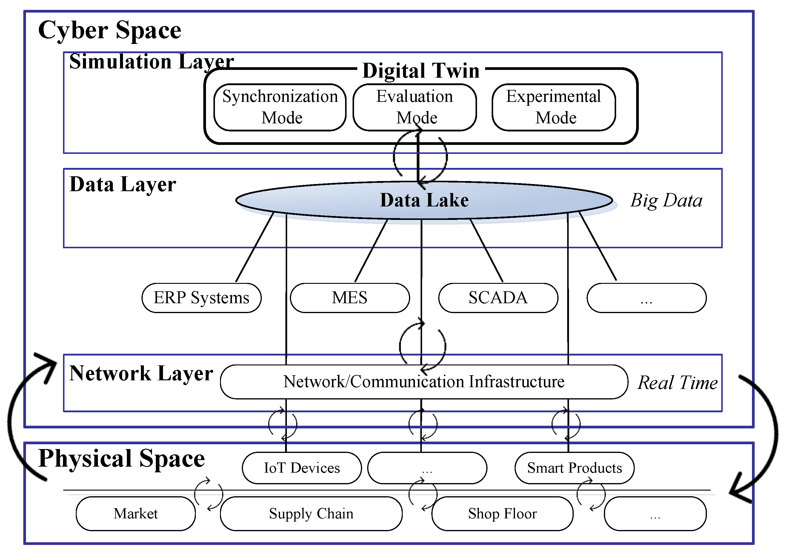
Different from the traditional simulation architecture, the simulation in DT is used as a validation tool for optimizing solutions rather than only visually displaying the simulation of random events [5]. Although the concept of the DT was born in the field of aerospace engineering for the re-engineering of structural life prediction and management, the concept has also been adopted in manufacturing contexts. The DT paves the way for cyber-physical integration and serves as a bridge between the physical world and the cyber world, providing manufacturing enterprises with a new way of implementing smart production and precision management [7]. A DT consists of a virtual representation of a production system that is able to use sensory data, connected smart devices, mathematical models, and real-time data elaborations. The DT can be run on different simulation disciplines that are characterized by the synchronization of virtual and real systems [9]. With its capabilities of conceptualization, comparison, and collaboration, the DT frees us from the physical realm, where humans operate relatively inefficiently [12]. The concept of the DT and its relation to the CPS considered in this study are shown in Figure 1.
In industrial practice, the definition and understanding of DT may be different by industry. For example, General Electric focuses on forecasting the health and performance of their products over their lifetimes [6], whereas some product developers regard DT as a set of augmented reality (AR) tools and integrate DT with other computer-aided design software to improve product development efficiency. By integrating these definitions of DT in various industries, we think that a DT should include the functions of real-time synchronization, prediction, and testing. In order to achieve these three functions, the DT should be executed separately in three modes, that is, synchronization mode, evaluation mode, and experimental mode.
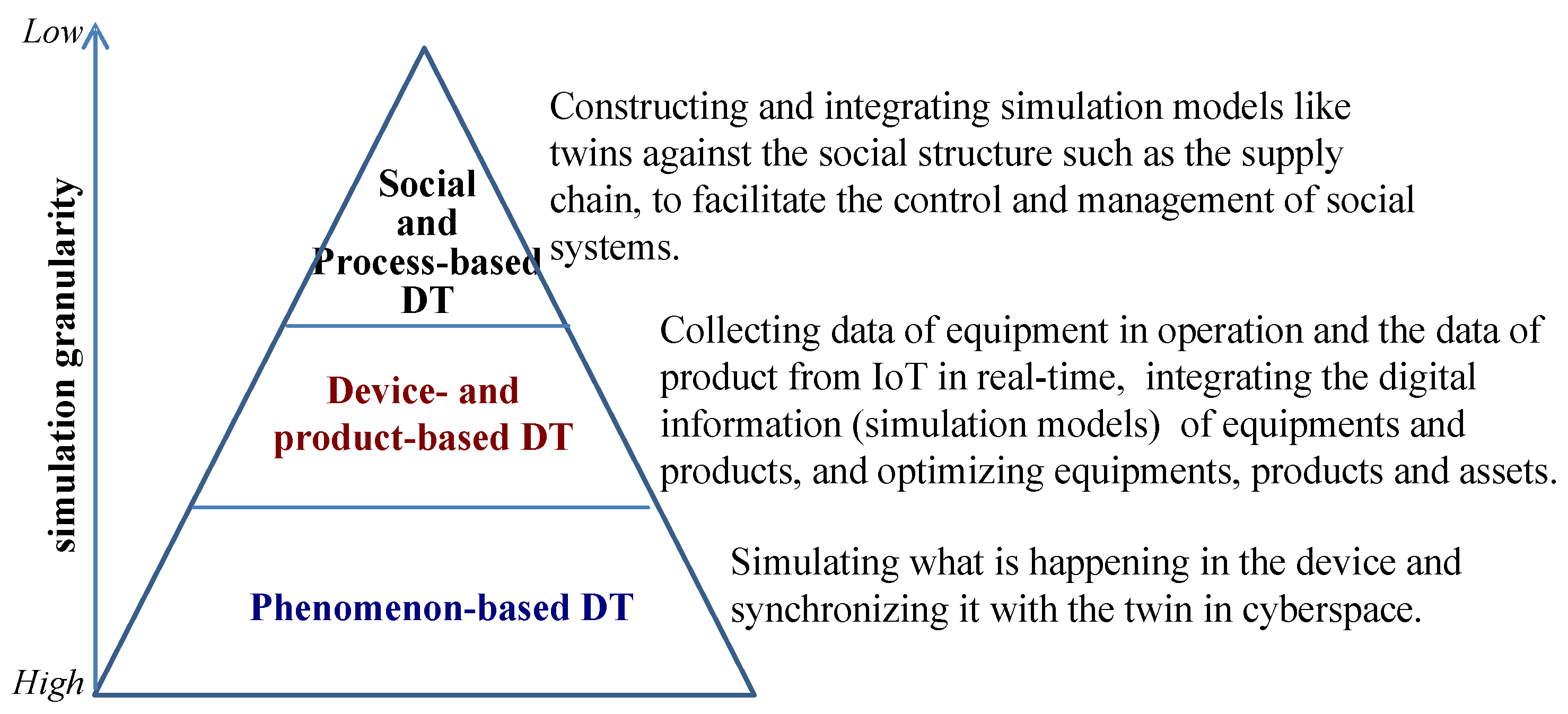
A DT is realized through simulation software, hardware, and data transmission and processing techniques in addition to other components. From the perspectives of simulation granularity and scope of analysis, a DT can be classified into three levels from the bottom to the top: phenomenon-based, device- and product-based, and social and process-based. Figure 2 shows a hierarchical structural diagram of a DT.
In the conventional simulation model, stochastic or deterministic parameters are assigned to a specific simulation model all at once and the results are analyzed on the basis of these data. The model itself is usually fixed and seldom changed. However, manufacturing and logistics in the real world are affected by their internal and external environments, so their characteristics and functions may change frequently and quickly, possibly leading to an increasing gap between the simulation model and reality. Contrary to this weakness in conventional simulation models, the DT always uses the latest information to synchronize the mirroring of real-world behaviors so that the virtual models can be closer to reality and perform more complex simulations.
With the utilization of DTs, it is possible to visually check and inspect the states of manufacturing plants even from remote areas. Furthermore, by virtualizing the processes from product design to production, operation, and maintenance, the DT integrates the whole factory into the simulation models in cyberspace, facilitating the control and management of the factory in physical space to achieve efficient smart manufacturing.
3. Digital Twin and Monitoring Systems
The DT may not be a new concept if we only consider it as a tool for monitoring things and behaviors in the real world through the digital world, because digital mock-up technologies based on monitoring systems and 3D models are being widely used. However, with technological innovations, such as IoT, artificial intelligence (AI), and big data, the necessity for DTs is increasing more than ever and their applications continue to expand.
Even though a monitoring system may observe movements in the real world, it cannot be used to predict the occurrence of a failure or irregularity. Moreover, it cannot be used for hypothetical experiments or predictive analytics but only for gathering data from the real world and compiling and displaying them in the digital world. It does not provide a mechanism for feeding the decision support information back to the real world to allow for optimization.
Addressing the above problems, the DT is a simulation method that can be used for evaluation and optimization. As shown in Figure 1, the DT continuously acquires data from a data lake and incorporates the data into a real-time simulation model. In real time, the data lake gathers and stores data from machines and sensors connected to industrial equipment in the real world. After the DT processes and analyzes the data, the results are fed back to physical space to optimize the real-world system. The DT is a concept that applies a CPS to the field of manufacturing. A DT compares and analyzes sensory data obtained from the IoT with computer-aided design data derived from a product design, and then incorporates the data into a module inside a synchronous simulation model for monitoring. Compared to traditional monitoring systems, the DT not only represents the real world but also makes predictions, provides solutions, and supports decision-making before a failure or anomaly occurs. Thus, the DT simulates possible future events. As a result, it can prevent unplanned shutdowns and their incurred costs. The DT has been listed by major industrial equipment manufacturers, such as General Electric and Siemens, as an important technology for supporting the next generation of Industrie 4.0.
4. Framework for Constructing Digital Twin-oriented Simulations
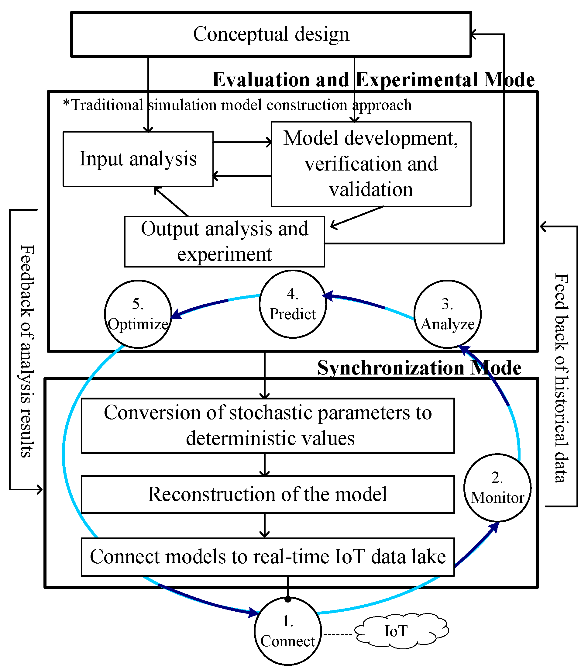
As mentioned above, the DT is still at the conceptual stage and only a few studies specifically mention model construction and implementation methods. In this paper, we propose a framework for constructing a DT in an IoT-aided manufacturing environment. The proposed framework is shown in Figure 3.
In this study, we propose that a DT should include the functions of real-time synchronization, prediction, and testing. To perform these three functions, the DT should be executed separately in three modes, which are synchronization mode, evaluation mode, and experimental mode. The evaluation mode and the experimental mode are actually provided in conventional simulation models which are often used for what-if analysis and optimization. Unlike the evaluation mode and the experimental mode, the synchronization mode is a mode unique to the DT. The DT is constantly updating of the simulation model with data being drawn from the IoT.
As shown in Figure 3, the first step in building a DT model is to design the concept. Next, similarly to the typical process of constructing a conventional simulation model, after performing the input analysis, a simulation model using stochastic data is constructed and validated. This simulation model can be used for the evaluation mode and experimental mode for prediction and optimization. After constructing a model using stochastic parameters, a simulation model is built for the synchronization mode. To use the real-time data of the IoT to synchronize the physical world, it is necessary to convert the stochastic parameters in the model into deterministic parameters to reconfigure the model. We can use the synchronization mode to monitor behaviors in physical space and save the historical data gathered from the IoT. Those historical data can be converted into stochastic distributions assigned to the simulation models of the evaluation and experimental modes, of which the results are fed back to the model of the synchronization mode.
5. Proposal for Data Input Scheme for Simulation Model Construction of a Digital Twin
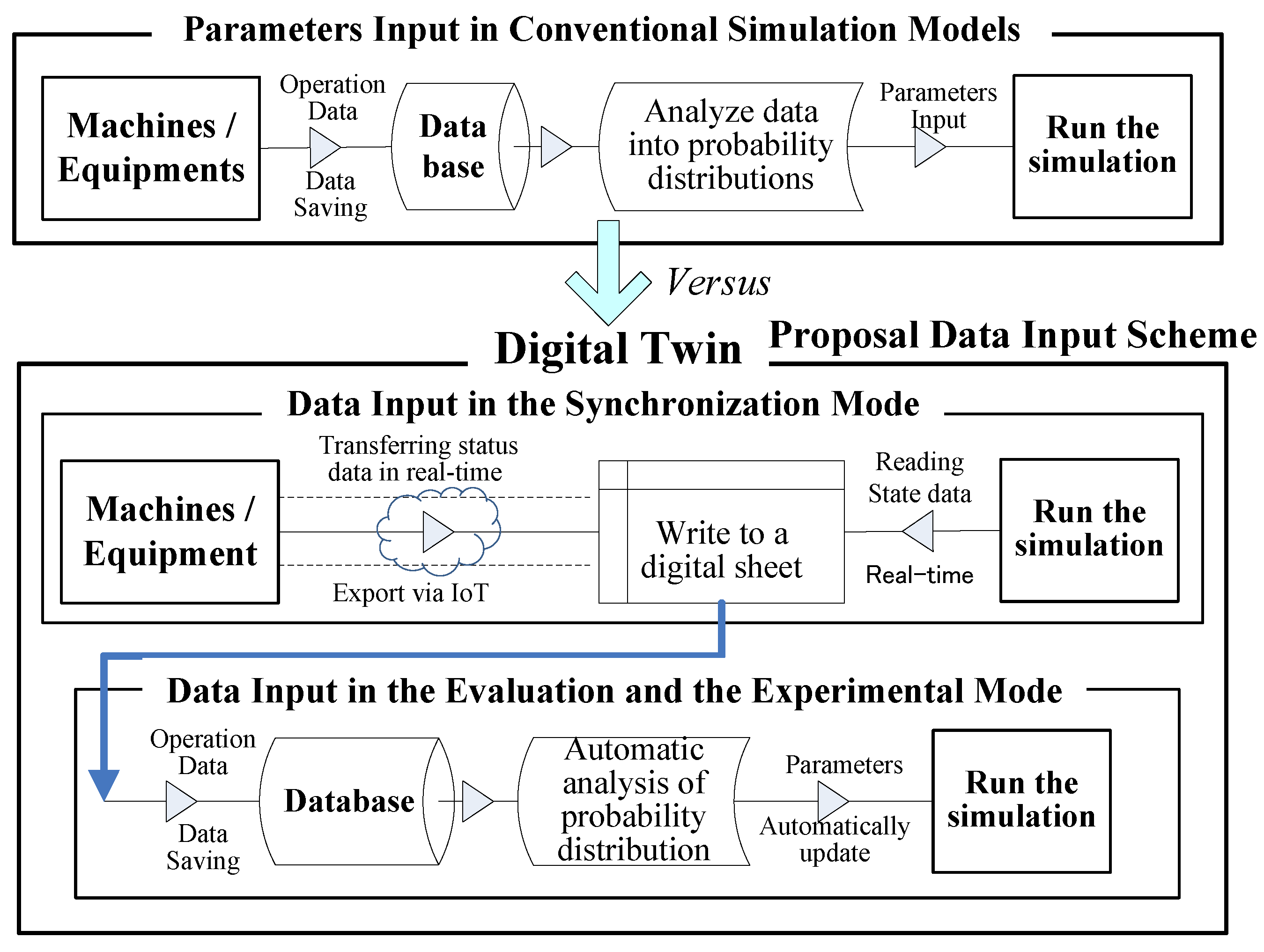
Generally, in constructing a simulation model, data inputs with randomness are employed to model the uncertainty events. When entering the parameters into a simulation model, instead of directly inputting the observed data, the probability distributions estimated from the observation value are utilized, and the model is executed. Distributions such as the triangular distribution and the normal distribution together with the associated parameters are specified as the input of the simulation model, especially for processing time and interval time, and so on.
Naturally, entering parameters with randomness into the model also leads to the randomness of execution results (outputs). Therefore, to obtain statistically significant results, it is necessary to perform statistical analyses on the repetitive execution results of the model. However, when constructing the synchronization mode (the real-time simulation) in DT, to express the behavior in the physical world as it is, the simulation needs to be carried out at the actual-time progressing speed. Therefore, it is necessary to avoid entering parameters with randomness, which causes random outputs, into the model as much as possible.
For this reason, we propose a data input scheme, as shown in Figure 4, for simulation models in a DT. When constructing a synchronization mode in DT, we enter the data into a simulation model by using a numerical sheet such as an Excel sheet, rather than probability distribution parameters. The digital sheets in the database collect and record the status data of the machines (e.g., instant processing time) in real-world production systems in real time via IoT. Then, the simulation model reads the status data from the digital sheet in real time and executes the simulation. Figure 4 indicates the differences between the conventional and DT simulation models in the data entry scheme.
As shown in Figure 4, these real-time data collected from the machines and equipment written to the digital sheet is aggregated and stored in a database. The evaluation and experimental modes of the DT will then read the historical data stored in the database and enter the fitted probability distribution parameters into the simulation model.
6. Application of Digital Twin Construction
To validate the proposed DT construction framework and data input scheme, a DT-oriented simulation model for an IoT-aided manufacturing factory model was constructed.
6.1. General Description of a Factory Simulation Model
The distributed model used in this study is an adoption of the Fischertechnik® Factory Simulation 9V model [13]. Table 1 shows a process schedule and processing parameters for this factory model. An overhead view and overlapped processing map of the factory is shown in Figure 5. The letters A to H in the circle represent the task codes shown in Table 1.
As shown in Figure 5, this factory model consists of three main parts: the Controller Automated High-Bay Warehouse with a Vacuum Gripper Robot (VGR), Controller Multiprocessing Station with Oven, and Controller Sorting Line with Detection. This system simulates a series of basic processes, including material storage, multiprocessing, and product sorting.
Workpieces are stored at the high-bay warehouse, which is designed as a pallet rack storage system for storing and retrieving goods. These are handled by a rack feeder that moves in a lane between three rows of racks. This area is part of the receiving station, where the identification of goods takes place. This is known as a conveyor system with identification, as the workpieces are transferred by a conveyor belt and identified by a barcode reader. Then, the workpieces are handled and transported by VGR A from the storage area to the processing area, where the workpiece automatically runs through several stations.
Processing begins with the oven, which represents the firing process. The light barrier is interrupted when a workpiece is placed on the kiln feeder, triggering the opening of the oven’s door and drawing in the kiln feeder. At the same time, VGR B is requested to transport the workpiece to the turntable after the firing process is complete. The turntable positions the workpieces under the saw for processing and conveys them to the ejector, which slides the workpieces onto the conveyor belt to carry to the sorting area.
The sorting line is used for the automated separation of different colored workpieces by color detection, which is handled by a color sensor that detects color on the basis of different surface reflections. With the help of a pulse switch, the workpieces are transferred to the correct position and pushed to the appropriate storage locations by the ejector. Meanwhile, several light barriers monitor the fill level of the storage locations. The system’s control logic, such as the warehousing principle, VGR movements, machine processing time, and sorting into the storage locations, are programmed by ROBO Pro and controlled with TXT controllers.
6.2. The IoT-Aided Manufacturing System in the Factory Model
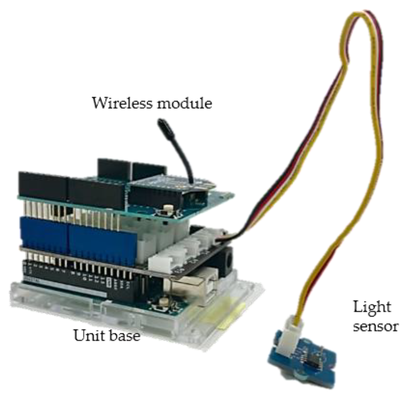
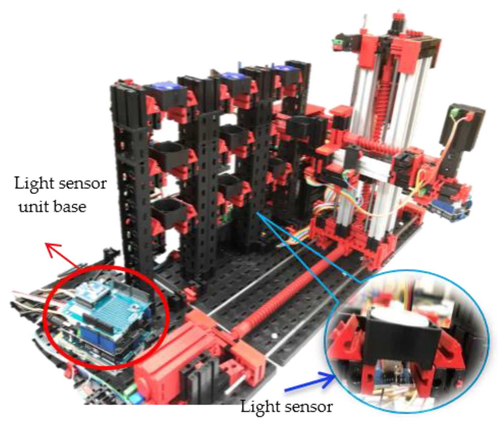
Although Fischertechnik’s Factory Simulation 9V model is equipped with some sensors, such as color sensors, it is not connected to the Internet and does not have the structure or functionality of the IoT. To convert this factory model into an IoT-aided manufacturing system, we added eight sets of light sensors wirelessly connected to the Internet. Figure 6 shows an example of a light sensor unit with a wireless module. As an example of the IoT system, the high-bay warehouse area with built-in light sensors is shown in Figure 7. The positions where other light sensors are installed are marked in Figure 5. The sets of the light sensor units are numbered. With the light sensor, we can obtain the working status and operating time of each machine.
To construct a DT model, we need to receive data from the sensors connected to the IoT and save the data to a data lake (see Figure 1). We receive data wirelessly from the light sensors in real time and utilize the data to build a DT-driven simulation model. To wirelessly receive and record data from the factory model, we use an Arduino microcomputer with sensors and Microsoft Excel VBA programs.
The Arduino has an original application development environment based on C/C++. For the sensors, we used Grove Light Sensor v1.2 and Grove Ultrasonic Ranger (Seeed Studio). The former sensor sent a changed value depending on the light intensity to Arduino as a signal, while the latter sensed the distance of an object away from it. A total of 8 sets (16 units) of sensors were installed and assigned numbers from 1 to 8 according to their locations, as shown in Figure 5.
To wirelessly send the data, an XBee ZB (S2C) (manufactured by Digi) was attached to the Arduino (Figure 6). Along with the defined algorithm in Arduino, the Arduino received signals from the sensors and sent the sensor number to the computer if the condition set by the algorithm was satisfied.
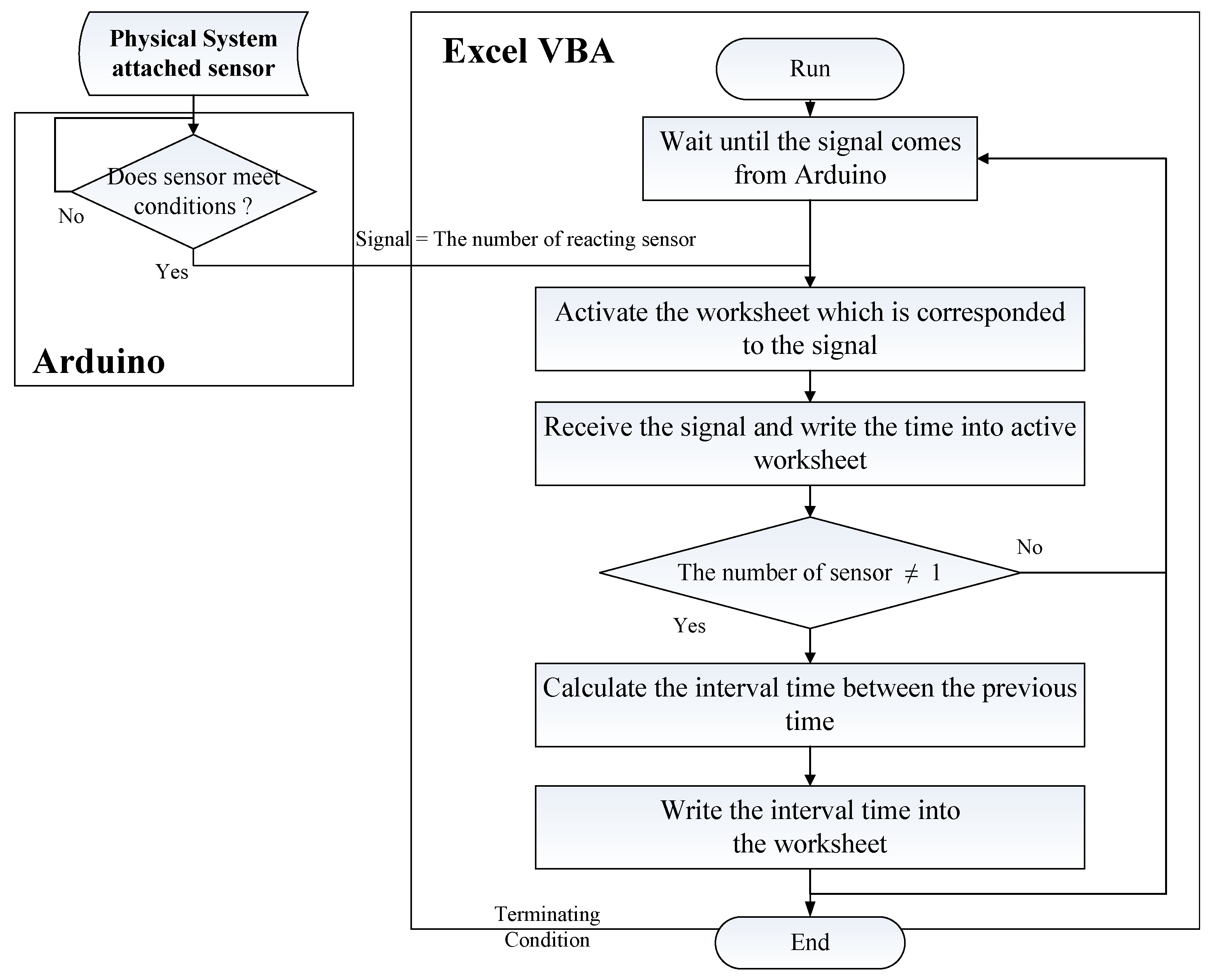
An Excel VBA program was also developed. When Excel received a signal from the Arduino, the time of the reception was recorded in a worksheet in real time. If the reaction sensor was not Sensor No. 1, the program calculated the interval between the current and the previous time, then wrote the interval times onto a specific worksheet. Then, a VBA module, EasyComm, received the signal via serial communication. Figure 8 shows the flow of the processing logic of the Excel VBA program.
6.3. Construction of Prototypical Model for DT-Oriented Simulation
To validate the proposed DT construction framework and data input scheme, we developed a DT-oriented simulation model for the factory model. The simulation model was programmed in Arena [14] and overlaid on a scaled layout. The main stochastic parameters were the processing time and resources used by each process, as shown in Table 1.
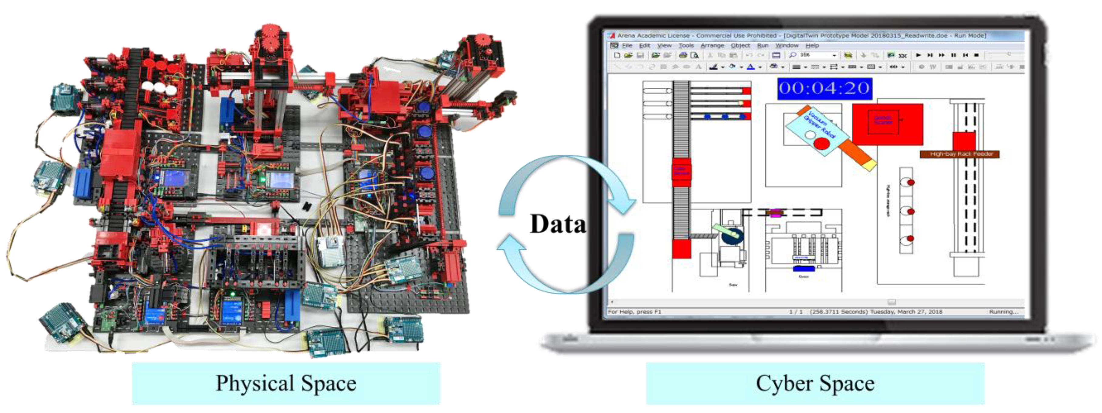
According to the framework proposed in Figure 3, we firstly constructed a conventional simulation, using the stochastic parameters for evaluation and optimization. Subsequently, we converted the stochastic parameters into deterministic parameters and rebuilt the model. When the model was executed, Excel acquired the data from the IoT in real time according to the processing logic shown in Figure 8, and then the simulation model continuously updated the parameter values by reading the data from Excel. This model was used to monitor and synchronize the behavior in physical space. The historical data were fed back to the simulation models for evaluation and experimental mode to calculate the stochastic distribution of the stochastic parameters (Figure 4). A DT schematic diagram of this factory is shown in Figure 9. Now, there are three modes for the DT-oriented simulation model, namely the evaluation model, the experimental mode and the synchronization mode. We can use these simulation models according to our needs.
6.4. Experiment and Results
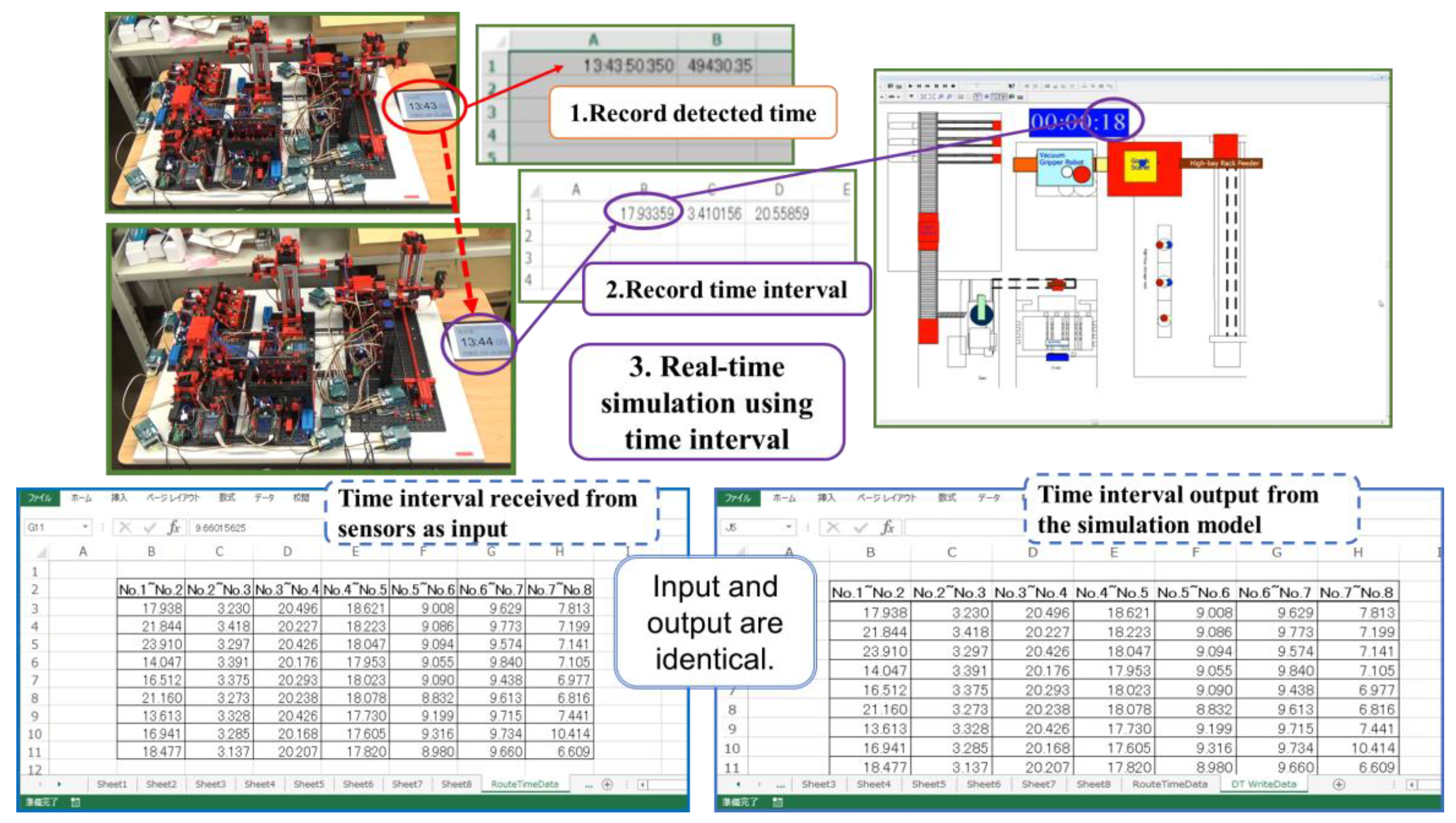
After building the DT model, it was validated by an interactive process between the factory model and the simulation model modelers. This process compared the model’s output with the actual sensory data. After confirming the reliability of the model, the simulation models were run and the results were analyzed. Figure 10 shows a synchronized display of experimental results on the input and output of workpiece interval time between physical and cyber sides. As shown in Figure 10, the time interval received from sensors as input from the real world is exactly the same as the interval time output from the simulation model on cyberspace. It was confirmed that the synchronization mode of the DT simulation could accurately mirror the actual behavior of the factory model.
The main research objectives of this study are to propose a framework and a data input scheme for the construction of a DT, as well as develop a prototype model for the DT based on the proposed framework. Therefore, this article does not focus on the what-if analysis of the experiment. However, from the operational experiment, we obtained the following findings:
- The DT’s synchronization mode can be used to remotely observe the factory’s operation and the statuses of the machines via a network. However, the DT differs from the conventional monitoring system in that it can quantitatively grasp an entity’s time-related performance indicators, resource utilization, etc.
- Like the conventional simulation model, the DT’s evaluation mode can be used to predict the system’s behaviors, such as machine failures and entity cycle times.
- The DT’s optimization mode can be used to optimize a system just like the conventional simulation model. This mode can be used to seek and find a solution, such as shortening the lead time of orders, by scenario comparison analysis.
7. Conclusions
The IoT is recognized as a technology that has already had economic impacts and created high expectations for drastically changing the competitive domain in various industries. In the manufacturing field, sensor-equipped machines can collect data from the production system in real time. On the cyber side, the DT has been proposed as a tool for collecting and synchronizing real-world information in real time. By updating data in real time and comparing cyberspace with physical space in parallel, the DT can be continuously improved and synchronized with the real world. Although the DT is considered a challenging technology, it is still at the conceptual stage.
In this study, in order to develop the DT, we proposed a framework for constructing a DT. We proposed that the DT should contain three execution modes, that is, the evaluation mode, the experimental mode, and the synchronization mode. The evaluation mode and experimental mode can be developed as conventional simulation models using stochastic parameters for prediction and optimization. Therefore, the DT’s evaluation mode can be used to predict machine failures and test failure avoidance methods. The synchronization mode is used to observe the factory’s operation and the machine status remotely via a network, but differs from a conventional monitoring system.
Traditionally, randomness is adopted to execute simulation experiment. However, when constructing the synchronization mode in DT, it is necessary to avoid entering parameters with randomness. For this reason, we proposed a data input scheme for inputting data derived from the IoT into a simulation model of a DT.
In order to verify the effectiveness of the framework as a prototype of a DT-oriented simulation model, a DT-oriented model for an IoT-aided bench-scale factory system was constructed. In this factory model system, to simulate the IoT environment, we modified a simple IoT system by attaching some sensor units. With the proposed framework for DT construction and proposed data input scheme, we were able to receive real-time data from an IoT-aided manufacturing system and construct a DT model that successfully reflected the real situation of the physical system. A simulated factory model was developed for research and education.
In this study, a digital twin was constructed for a bench-scale model of the factory. In actual factories, increasing the number of devices and processes may increase the complexity of the model. In that case, further discussion is still needed on how to efficiently input large amounts of data into the simulation model. In addition, when considering the implementation of a smart factory, there remains a problem of connection experiments between ERP (Enterprise Resources Planning), MES (Manufacturing Execution System) and simulation. Furthermore, what-if analysis using digital twin should be done, following this study. Forecasting, experimentation and optimization are other important features of DT to predict the future status or performance. These issues should be developed and examined in future researches.
Author Contributions
Conceptualization, Y.T., W.Y. and S.T.; methodology, Y.T. and W.Y.; simulation models development, Y.T., K.Y. and W.Y.; IoT-aided factory model construction, K.Y.; model validation, Y.T., W.Y., K.Y. and S.T.; writing—original draft preparation, Y.T., W.Y. and K.Y.; writing—review and editing, S.T. and W.Y.; supervision, S.T.; funding acquisition, S.T. and W.Y.
Funding
This research was partly supported by JSPS KAKENHI, grant number JP17K12984.
Conflicts of Interest
The authors declare no conflict of interest.
References
- Lee, I.; Lee, K. The Internet of Things (IoT): Applications, investments, and challenges for enterprises. Bus. Horiz. 2015, 58, 431–440. [Google Scholar] [CrossRef]
- Gartner, Inc. Gartner Says 8.4 Billion Connected “Things” will be in Use in 2017, up 31 Percent from 2016. Available online: https://www.gartner.com/newsroom/id/3598917 (accessed on 25 March 2018).
- IDC. Worldwide Semiannual Internet of Things Spending Guide. Available online: https://www.idc.com/getdoc.jsp?containerId=IDC_P29475 (accessed on 25 March 2018).
- Posada, J.; Toro, C.; Barandiaran, I.; Oyarzun, D.; Stricker, D.; de Amicis, R. Visual Computing as a Key Enabling Technology for Industrie 4.0 and Industrial Internet. IEEE Comput. Graph. Appl. 2015, 35, 26–40. [Google Scholar] [CrossRef] [PubMed]
- Zhang, H.; Liu, Q.; Chen, X.; Zhang, D.; Leng, J. A digital twin-based approach for designing and multi-objective optimization of hollow glass prosution line. IEEE Access 2017, 5, 26901–26911. [Google Scholar] [CrossRef]
- Schleich, B.; Anwer, N.; Mathieu, L.; Wartzack, S. Shaping the digital twin for design and production engineering. CIRP Ann. Manuf. Technol. 2017, 66, 141–144. [Google Scholar] [CrossRef]
- Qi, Q.; Tao, F. Digital Twin and Big Data towards Smart Manufacturing and Industry 4.0: 360 Degree Comparison. IEEE Access 2018, 6, 3585–3593. [Google Scholar] [CrossRef]
- Gartner, Inc. Gartner Identifies the Top 10 Strategic Technology Trends for 2018. Available online: https://www.gartner.com/newsroom/id/3812063 (accessed on 25 March 2018).
- Negri, E.; Fumagalli, L.; Macchi, M. A Review of the Roles of Digital Twin in CPS-based Production Systems. Procedia Manuf. 2017, 11, 939–948. [Google Scholar] [CrossRef]
- Yang, W.; Tan, Y.; Yoshida, K.; Takakuwa, S. Digital Twin-Driven Simulation for A Cyber-Physical System in Industry 4.0. In DAAAM International Scientific Book 2017; DAAAM International Publishing: Vienna, Austria, 2017; pp. 227–234. ISBN 978-3-902734-12-9. [Google Scholar]
- Kecskemeti, K.; Casale, G.; Jha, D.N.; Lyon, J.; Ranjan, R. Modelling and Simulation Challenges in Internet of Things. IEEE Cloud Comput. 2017, 4, 62–69. [Google Scholar] [CrossRef] [Green Version]
- Grieves, M. Digital Twin: Manufacturing Excellence through Virtual Factory Replication. Available online: https://research.fit.edu/media/site-specific/researchfitedu/camid/documents/1411.0_Digital_Twin_White_Paper_Dr_Grieves.pdf (accessed on 25 March 2018).
- Fischertechnik. Factory Simulation 9V–Education. Available online: https://www.fischertechnik.de/en/products/teaching/training-models/536629-edu-factory-simulation-9v-education (accessed on 25 March 2018).
- Kelton, D.; Sadowski, R.; Swets, N.B. Simulation with Arena, 5th ed.; McGraw-Hill, Inc.: New York, NY, USA, 2010; ISBN 978-0071267717. [Google Scholar]
Figure 1.
Digital twin with a cyber-physical system.

Figure 2.
Hierarchical structure of digital twins.

Figure 3.
Framework for construction of a DT-oriented simulation model.

Figure 4.
Proposal of data input scheme for simulation models in a DT.

Figure 5.
Overhead view and the sequence of processes of the factory model.

Figure 6.
A light sensor unit body with a wireless module attached.

Figure 7.
High-bay warehouse area with built-in light sensors.

Figure 8.
Flow of processing logic of the Excel VBA program.

Figure 9.
A DT schematic diagram of the factory.

Figure 10.
Synchronized display of input and output of interval time between physical and cyber sides.
Figure 10.
Synchronized display of input and output of interval time between physical and cyber sides.


Table 1.
Process schedule and processing parameters in the factory model.
| Proc. Seq. | Task Code | Processes | Processing Time (Unit: Second) | Resources |
|---|---|---|---|---|
| 1 | A | Picking and transporting workpieces from high-bay rack to identification station | TRIA(13.4, 18.1, 26.3) | High-bay rack feeder |
| 2 | B | Scanning and carrying workpieces by conveyor belt to vacuum gripper robot | TRIA(3.60, 3.66, 3.71) | Conveyor system with identification |
| 3 | C | Picking and carrying workpieces to the multiprocessing station with oven | TRIA(20.7, 20.8,21.0) | 3D Vacuum Gripper Robot A |
| 4 | D | Processing by the oven | TRIA(17.6, 17.8, 17,9) | Conveyor belt, Oven |
| 5 | E | Picking and transporting workpieces to saw station | TRIA(9.1, 9.3, 9.4) | Vacuum Gripper Robot B |
| 6 | F | Processing by the saw | TRIA(9.73, 9.77, 9.89) | Saw, ejector |
| 7 | G | Color sorting line with detection | TRIA(7.3, 7.96, 9.37) | Color detection, conveyor belt, storage locations |
| 8 | H | Conveyor belt carries workpieces to storage location | TRIA(4,6,8) | Conveyor belt, storage locations |
| Note: TRIA(Min, Mod, Max) indicates the triangle distribution. | ||||
© 2019 by the authors. Licensee MDPI, Basel, Switzerland. This article is an open access article distributed under the terms and conditions of the Creative Commons Attribution (CC BY) license (http://creativecommons.org/licenses/by/4.0/).
Share and Cite
MDPI and ACS Style
Tan, Y.; Yang, W.; Yoshida, K.; Takakuwa, S. Application of IoT-Aided Simulation to Manufacturing Systems in Cyber-Physical System. Machines 2019, 7, 2. https://doi.org/10.3390/machines7010002
AMA Style
Tan Y, Yang W, Yoshida K, Takakuwa S. Application of IoT-Aided Simulation to Manufacturing Systems in Cyber-Physical System. Machines. 2019; 7(1):2. https://doi.org/10.3390/machines7010002
Chicago/Turabian StyleTan, Yifei, Wenhe Yang, Kohtaroh Yoshida, and Soemon Takakuwa. 2019. "Application of IoT-Aided Simulation to Manufacturing Systems in Cyber-Physical System" Machines 7, no. 1: 2. https://doi.org/10.3390/machines7010002
Note that from the first issue of 2016, this journal uses article numbers instead of page numbers. See further details here.