Article

Improved Commercially Pure Titanium Obtained by Laser Directed Energy Deposition for Dental Prosthetic Applications

1
LaserON Research Group, School of Engineering, CINTECX, University of Vigo, Lagoas-Marcosende, E-36310 Vigo, Spain
2
Corus-Fegoba, C/San Jorge 18, E-15002 A Coruña, Spain
3
School of Dentistry, Universitat Internacional de Catalunya, E-08195 Barcelona, Spain
4
Galicia Sur Health Research Institute (IIS Galicia Sur), SERGAS-UVIGO, E-36310 Vigo, Spain
5
Materials Engineering, Applied Mechanics and Construction Department, University of Vigo, EEI, Lagoas-Marcosende, E-36310 Vigo, Spain
*
Author to whom correspondence should be addressed.
Metals 2021, 11(1), 70; https://doi.org/10.3390/met11010070
Submission received: 7 December 2020 / Revised: 26 December 2020 / Accepted: 27 December 2020 / Published: 31 December 2020
(This article belongs to the Section Additive Manufacturing)

Abstract

:
The objective of this study was to evaluate the viability of the cp-Ti obtained through the laser-directed energy deposition (LDED) technique as a material for dental prostheses through an evaluation of the microstructural, mechanical, and electrochemical properties. Additionally, the material resulting from LDED is also compared with the same alloy employed for milling in the dental restorative industry. The results obtained show that both materials have good overall performance for biomedical applications according to the ISO 22674 and ISO 10271 dentistry standards. Both materials have high corrosion resistance, typical of this alloy. However, commercially pure titanium grade 4 obtained by LDED present a higher mechanical performance than the ones resulting from the milling technique: 7% increment of ultimate tensile strength, 12.9% increment of elongation after fracture and 30% increment of toughness. This improved mechanical performance can be attributed to microstructure modification inherent to the LDED process.

Graphical Abstract

1. Introduction

Additive manufacturing (AM) has evolved a lot in the last few decades. Firstly, AM was intended for fabricating prototypes with much less effort and celerity. However, its continuous evolution was obtained through significant advances in its constituent technologies such as improved reliable industrial laser sources, cheap high-performance computing hardware or evolution of metal powder manufacturing technologies [1]. These advances made AM a completely viable option for obtaining fully-functional final parts, efficiently creating complex components [2] and getting more and more competitive in large scale production. Nowadays, AM technologies are currently employed in several industries where the customization of the final part prevails: such as aerospace, automotive, or biomedical applications [3].
Direct energy deposition (DED) is a family of AM processes where the methodology of generating the final part is characterized for having a real-time delivery of the material and the energy at the same time during manufacturing [1]. Laser-directed energy deposition (LDED, Figure 1) is an AM technique of the DED family where the energy employed comes from a laser source. This technique is also known by other names such as laser engineered net shaping (LENS) [4], direct laser deposition (DLD) [5], or laser metal deposition (LMD) [6], among others. LDED is characterized by a good metallurgical bonding between layers [7] and a reduced porosity [8].
The same principle of this technique was firstly employed for coating generation, with the name of laser cladding, for a great variety of materials such as aluminum alloys for corrosion resistance [9], functionally graded materials [10], superalloys (wear resistance) [11], bioceramics (biomedical applications) [12,13], or bronze (tribological applications) [14]. However, nowadays this technique has been developed to generate functional parts using metals [15,16] or even ceramics [17]. That is why significant efforts have been made in recent years in order to fully understand the process through several approaches: residual stresses [18], grain evolution [19], layer height [20], or solidification behavior [21], among others. Additionally, with a correct control of the processing parameters, the microstructure of the final part can also be tuned [22], giving the capability of obtaining different properties of the material depending on the purpose of the final part.
Medical implant development in recent years has had great progress in material compatibility with the human body, and nowadays titanium is perceived as the biocompatible material par excellence. Its outstanding resistance to corrosion from body fluids joined with its compatibility with bone and living tissues are their principal advantages [23]. Also, Ti prostheses present fewer artefacts in computed tomography or MRI due to its reduced magnetic susceptibility [24]. All of this, along with its low modulus of elasticity, more similar to bone stiffness than other metals, gives the perfect material for biomedical applications. That is why it is employed in all kinds of prostheses, like dental restorations or dental implants [25,26].
Commercially pure titanium (cp-Ti) is a designation for titanium with a reduced content of alloying elements. This group of alloys are characterized for having a great resistance to corrosion in comparison with other titanium alloys [27]. Additionally, cp-Ti also presents reduced cytotoxicity for dental alloys in the gastrointestinal environment [28], reducing inflammatory responses.
The mechanical characteristics of cp-Ti alloys are greatly influenced by the oxygen content in the metal matrix [29]. Therefore, they are really susceptible to the presence of oxygen during manufacturing at high temperatures [30], leading to an embrittlement of the material if the oxygen levels are too high [31,32]. However, with correct manufacturing conditions, cp-Ti alloys possess great overall mechanical and electrochemical properties. One of these alloys is the cp-Ti grade 4, which is the most mechanically resistant commercially pure titanium alloy. It also maintains a good corrosion behavior, this is why it is the most employed cp-Ti for dental restorative prostheses.
Due to the fact that restorative prostheses, and in particular dental restorations, are fully designed for each individual patient, the employment of AM for the generation of them is completely justified. Recent studies have suggested the viability of using LDED technique with cp-Ti [33,34,35,36,37]. However, none of them has evaluated the material on an industrial level, or perform tests that follow quality standards. Therefore, a complete verification of cp-Ti for biomedical applications is needed in order to ascertain the compliance of the material produced by this technique on industry standards.
Therefore, the aim of this study was to evaluate the viability of the cp-Ti obtained through LDED technique as a material for dental prostheses through an evaluation of the microstructural, mechanical, and electrochemical properties following the ISO regulations. The material generated using LDED was also compared with a material employed for milling made from the same alloy currently being employed commercially in the dental restorative industry.

2. Materials and Methods

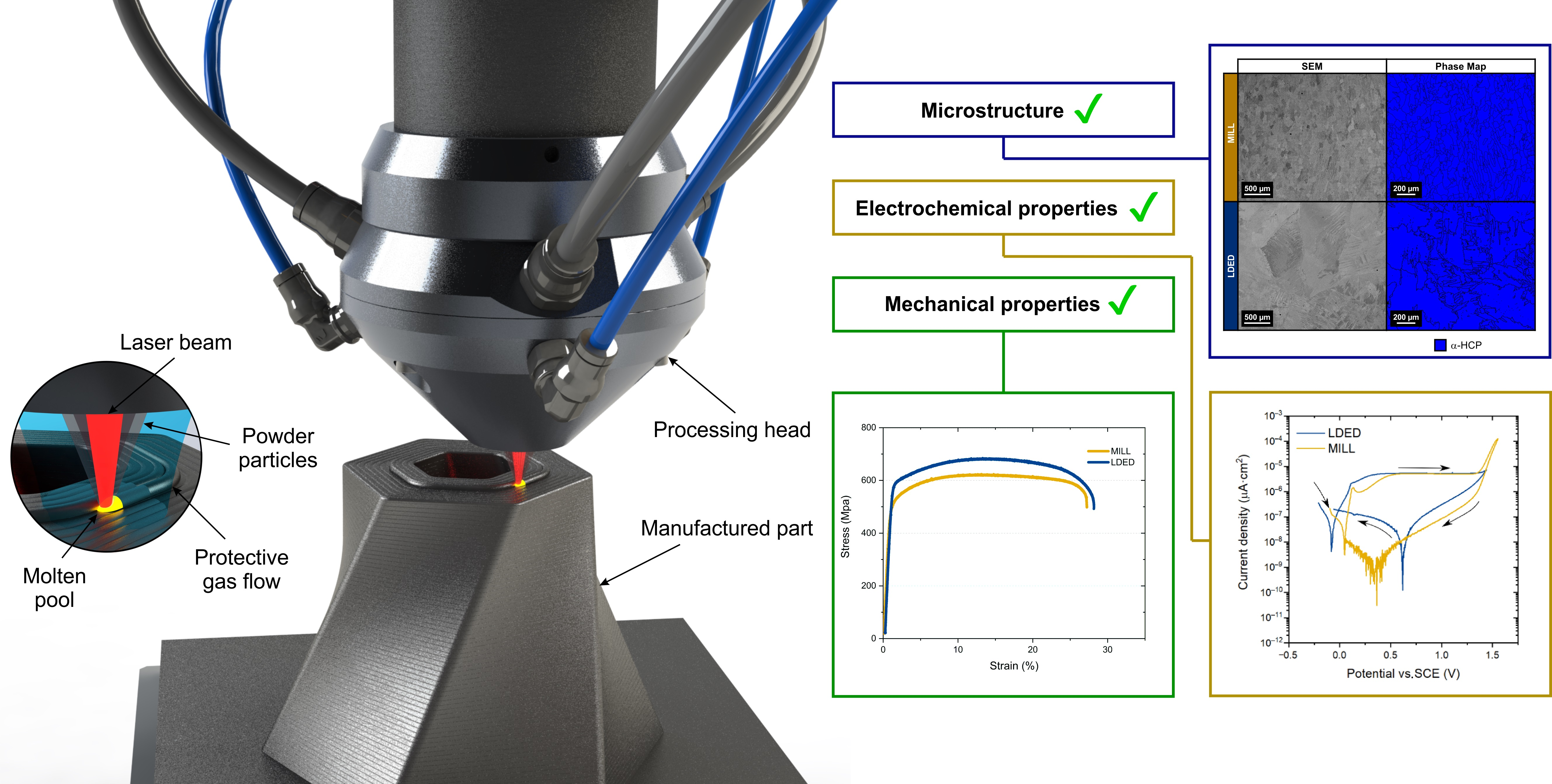
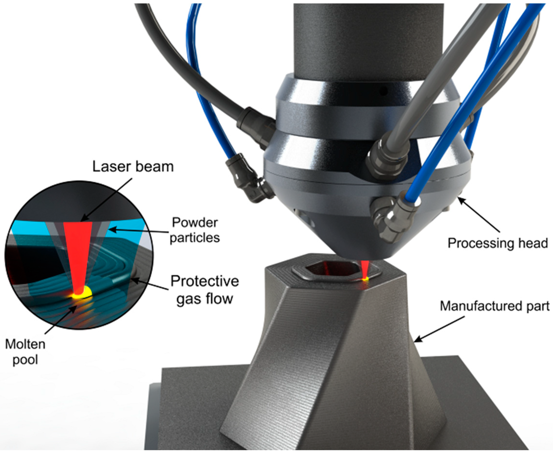
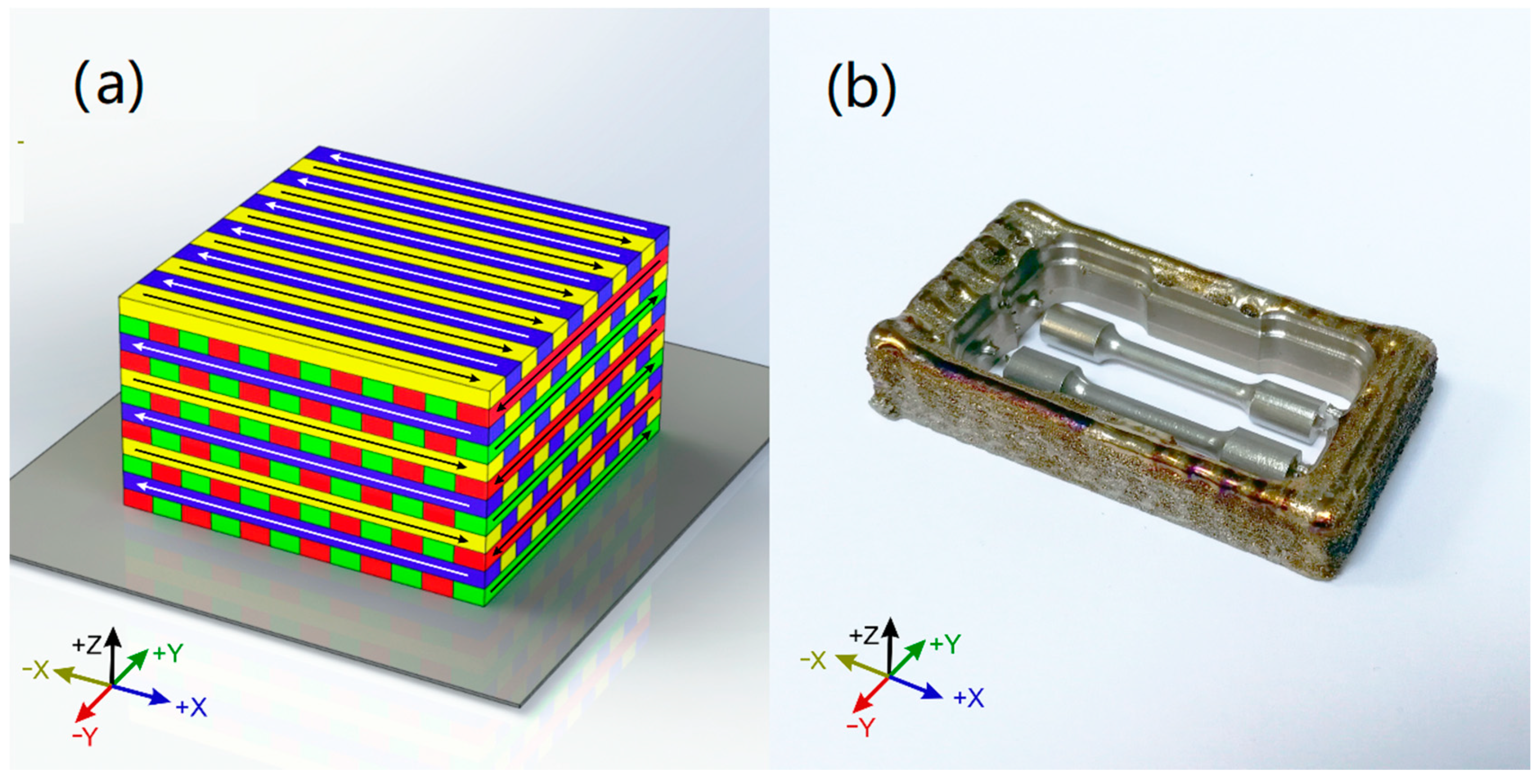
2.1. Specimen Generation

Two manufacturing techniques (MILL, LDED) were employed to manufacture the specimens of commercially pure Ti grade 4. The composition of the materials used in the present study was collected from manufacturers compositional certificates. In Table 1, these data are shown along with the maximum limits for surgical implants applications compiled from ISO 5832-2:2012 and ASTM F67 standards.
The milling (MILL) specimens were machined from commercial EUTITAN (Schütz Dental GmbH, Rosbach, Germany) dental discs (obtained via continuous casting and hot rolling, with a final annealing process) using a CAD/CAM milling machine (DT2, Dyamach Italia, Mussolente, Italy) and employing solid carbide cutting tools. The angle between axial disc direction and tensile directions of tensile specimens was 90°.
The laser directed energy deposition (LDED) specimens were generated using a system which was composed of a 1600 W high power diode laser (DILAS, Rofin-Sinar, Hamburg, Germany) (as a power source to generate the molten pool in a cp-Ti substrate), an argon-carried commercial pneumatic powder feeder (Sulzer Metco Europe GmbH, Kelsterbach, Germany), a coaxial injection powder system and a CNC controlled three-axis positioning system. The processing zone is enclosed in a controlled-ambient inert chamber that employed argon as a protective atmosphere under <50 ppm of O2. The process parameters were set as 140 W/mm2 of laser irradiance, 6 mm/s of processing speed, and 3.7 g/min of Ti powder flow. Commercial cp-Ti grade 4 powder (Metco 4010A), with a particle size between 10 and 70 µm, was used as precursor material. The generated specimens had cuboid shape: 70 mm× 35 mm× 10 mm. Scanning strategy employed was a back-and-forth strategy (Figure 2a) with 90° rotation in scanning direction between layers, being each layer perpendicular to the previous one. Layer height has been set to 0.40 mm and the distance of adjacent paths to 2.25 mm (28.5% of overlap ratio). After that, the specimens were separated from the building plates and were machined in a milling CAD/CAM system (DT2, Dyamach Italia, Mussolente, Italy), being the angle between the building direction and the tensile direction of tensile specimens 90° (Figure 2b).

2.2. Microstructural Characterization

For microstructural analysis, materials of both processes (MILL, LDED) were examined using an optical microscope (Nikon, SZM-10, Tokyo, Japan) and a scanning electron microscope (SEM, Philips XL30, FEI Technologies Inc., Hillsboro, OR, USA) assembled with an energy-dispersive X-ray spectroscopy unit (EDS, EDAX PV9760, EDAX Inc., Mahwah, NJ, USA). Samples (10 mm × 10 mm× 10 mm) were cut form the cuboids, embedded in epoxy resin, ground, and polished using colloidal silica suspension (0.04 μm) as the final step. Polished surfaces were imaged using backscattered electron imaging (BSE) that employed 20 kV of accelerating voltage and 10 mm of working distance. The elemental composition mapping was verified via EDS under the same working conditions as BSE and 60 s of acquisition time. Semi-quantitative analysis of the mapping results was generated using ZAF correction. The crystallographic texture was analyzed via electron backscatter diffraction (EBSD, Oxford HKL Channel 5 (Oxford Instruments, Abingdon, UK) detector assembled on a dual-beam FEI HELIOS 600 NanoLab (FEI Technologies Inc., Hillsboro, OR, USA)).
For X-ray diffraction analyses, other specimens were cut in half and ground using 320 grit SiC paper. After that, they were scanned (XRD, Siemens D5000, KS Analytical Systems, Aubrey, TX, USA) with monochromated Cu-Kα radiation (λ = 1.54 Å) with a 2θ range of 20–130° (40 kV, 30 mA, 0.05° step size, 3 s step time).
Additionally, density of the two materials (MILL, LDED) was measured following the Archimedes method, using ethanol 96% at 20 °C as reference fluid (density = 0.805 g/cm3; this test fluid was used to avoid formation of air bubbles on the sample surface), and a digital scale (SBA 41, Scaltec Instruments, Heiligenstadt, Germany) [38].

2.3. Mechanical Characterization

Tensile mechanical tests were performed in accordance with ISO 22674:2016 standard. A total of six samples of each technique were generated for the tensile tests as well as marked for elongation measurements. A tensile test machine (LFV 25, Walter + Bai AG, Löhningen, Switzerland) equipped with an extensometer (3542-010M-020-ST, Epsilon Technology Corporation, Jackson, WY, USA) was employed, setting the stroke motion at 1.5 mm/min. After the fracture, all the samples were joined together and, using an optical microscope equipped with a micrometric positioning table, the distance between marks was measured. The modulus of toughness was independently calculated by means of the integration of the tensile tests stress–strain curves.
The Vickers hardness was measured following the ISO 6507-1:2018 standard and using microindentation (microindenter Shimadzu HMV-G, Shimadzu Corporation, Kyoto, Japan), as well as applying a load of 1 kp for 10 s of dwell time. The test was repeated in five different zones of the samples and averaged in order to achieve a representative measurement of the materials.
The fractographic analysis was performed by analyzing the fractured surfaces of the tensile tests using optical microscopy (SMZ1000, Nikon Metrology, Brighton, MI, USA) and SEM. All samples were carefully placed with the vertical axis of the images aligned with the building direction of the samples. Therefore, the possible influence of building direction can be assessed.

2.4. Electrochemical Characterization

The electrochemical tests were performed in accordance with the ISO 10271:2011 standard. Potentiodynamic polarization scans were conducted using a vertical cell of three electrodes (Autolab PGSTAT302N, Metrohm Autolab B.V., Utrecht, The Netherlands) in the presence of artificial saliva (AS). The AS was elaborated by adding 9.0 g of NaCl in 950 mL of distilled water. After that, NaOH was added until the pH was adjusted to 7.2 ± 0.1. Finally, water was added to obtain 1000 mL of the final liquid. A saturated calomel electrode (SCE) was used as the reference electrode, the samples of each test were employed as working electrodes with a surface of contact of 1 cm2 and a platinum mesh was employed as counter electrode.
Two variations of electrochemical tests were performed. The first one was done in an aerated medium, for simulating the usual oral environment, and the second one was done in a deaerated medium (under argon atmosphere), in order to simulate the small gaps with oxygen deprivation that can appear in the oral medium. Therefore, two samples (one for each test) for each technique were generated and ground with 320 grit SiC to homogenize the surfaces. After that, at least two repetitions of each sample in different zones were made to achieve a more representative measurement.

2.5. Statistical Analysis

Data analysis and statistical computing of the results of the tests were processed using R-project (v.3.6.3, The R Foundation for Statistical Computing, Vienna, Austria) for all recollected data. Mechanical data were compared using two-way ANOVA followed by the Tukey HSD test (level of significance = 0.05).

3. Results and Discussion

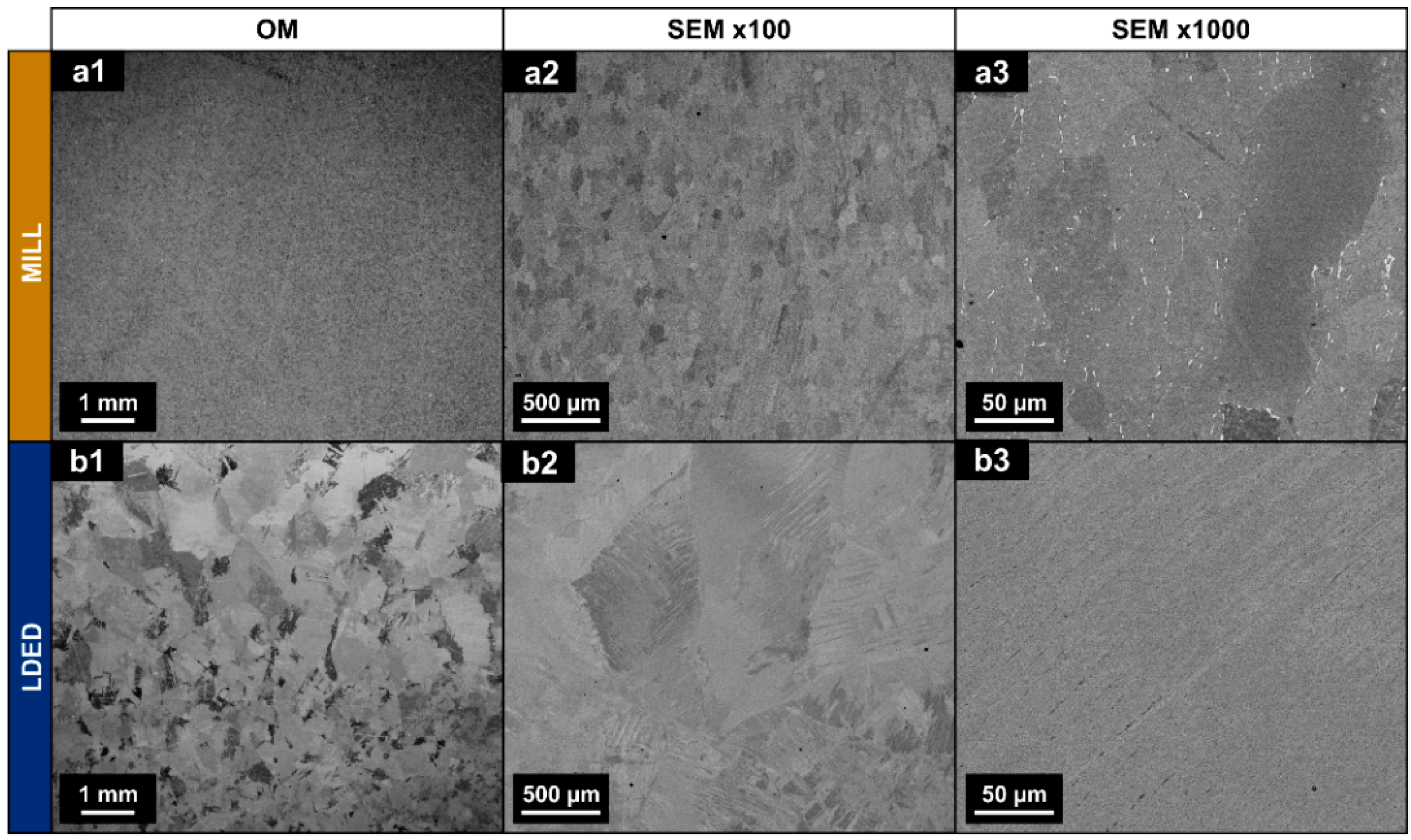
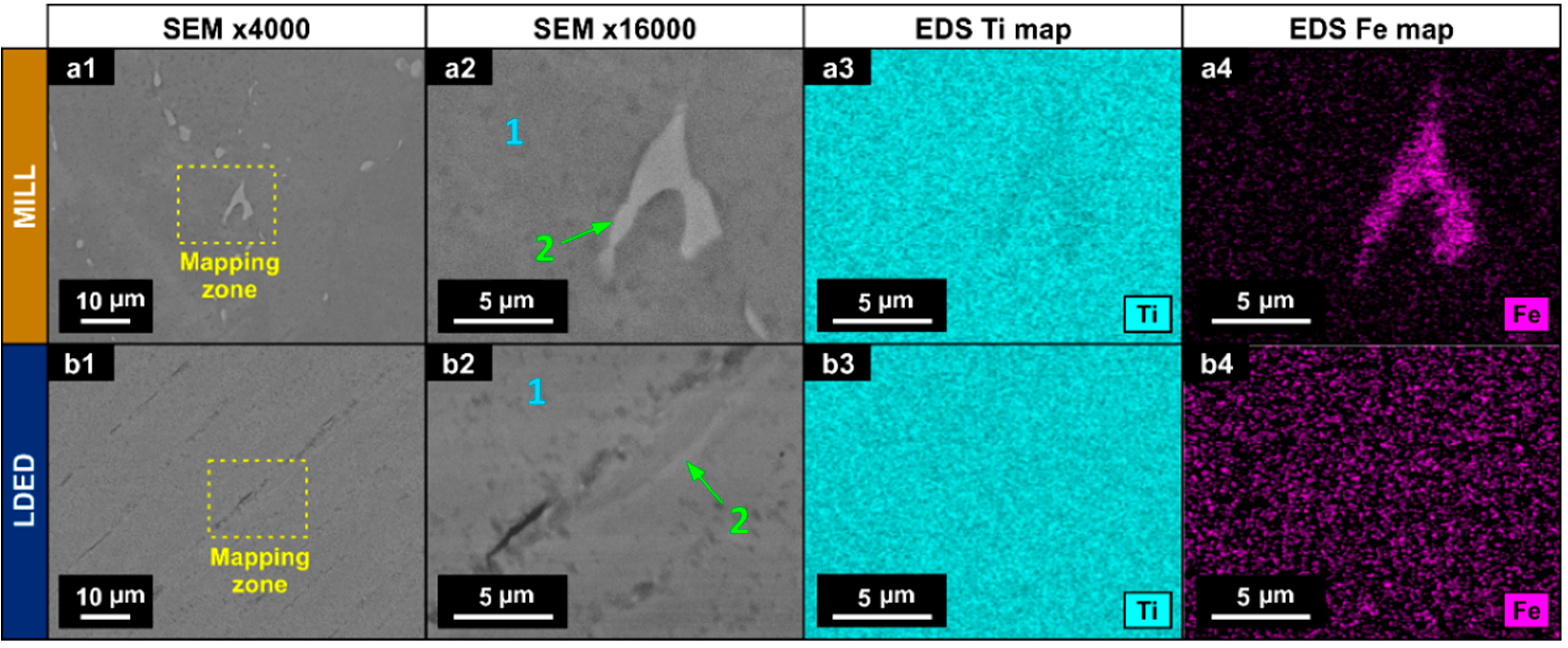
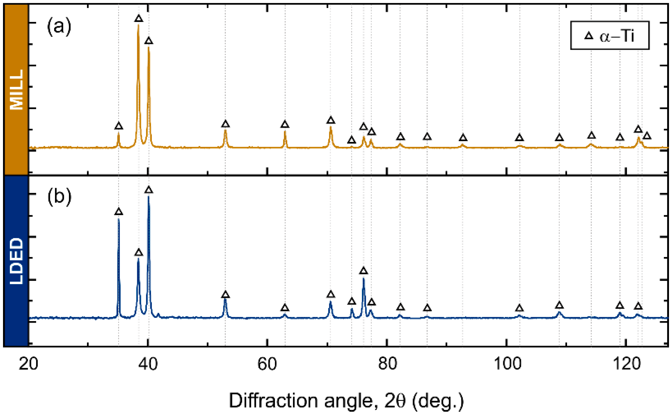
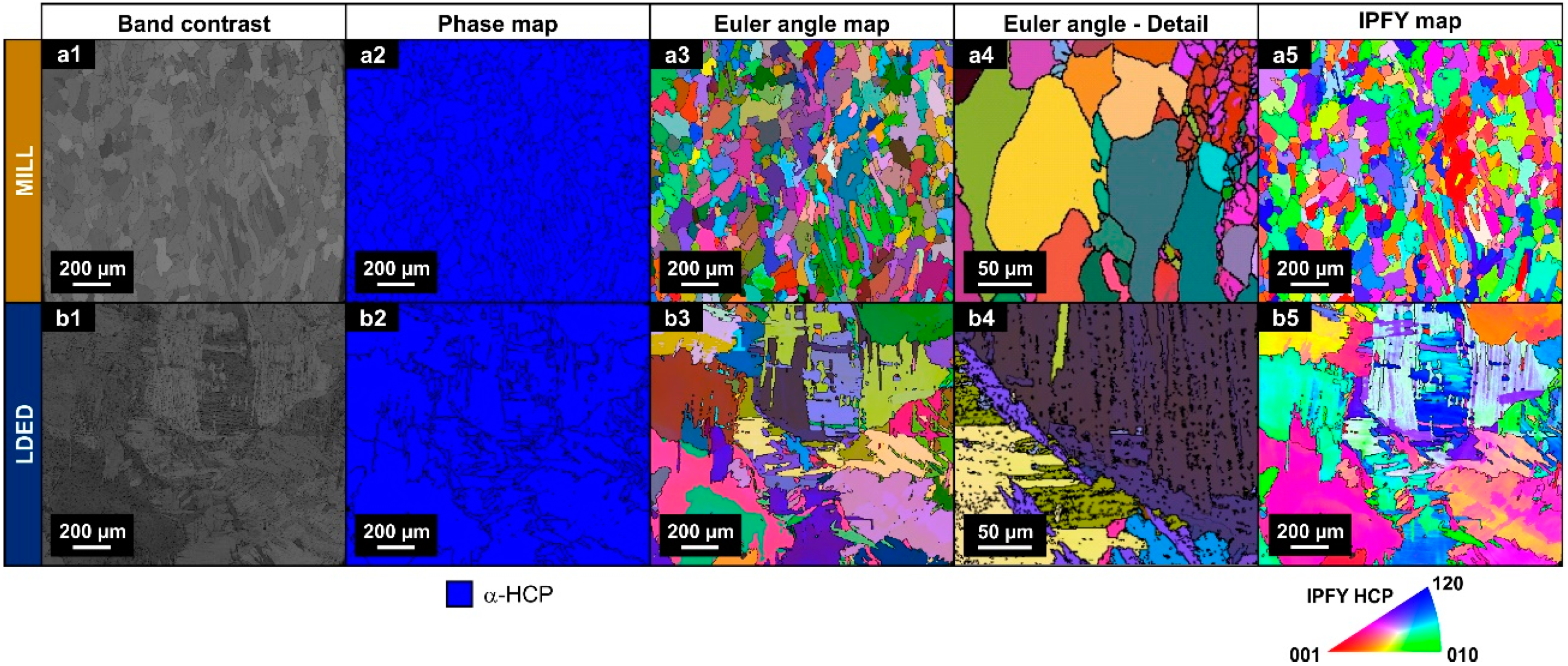
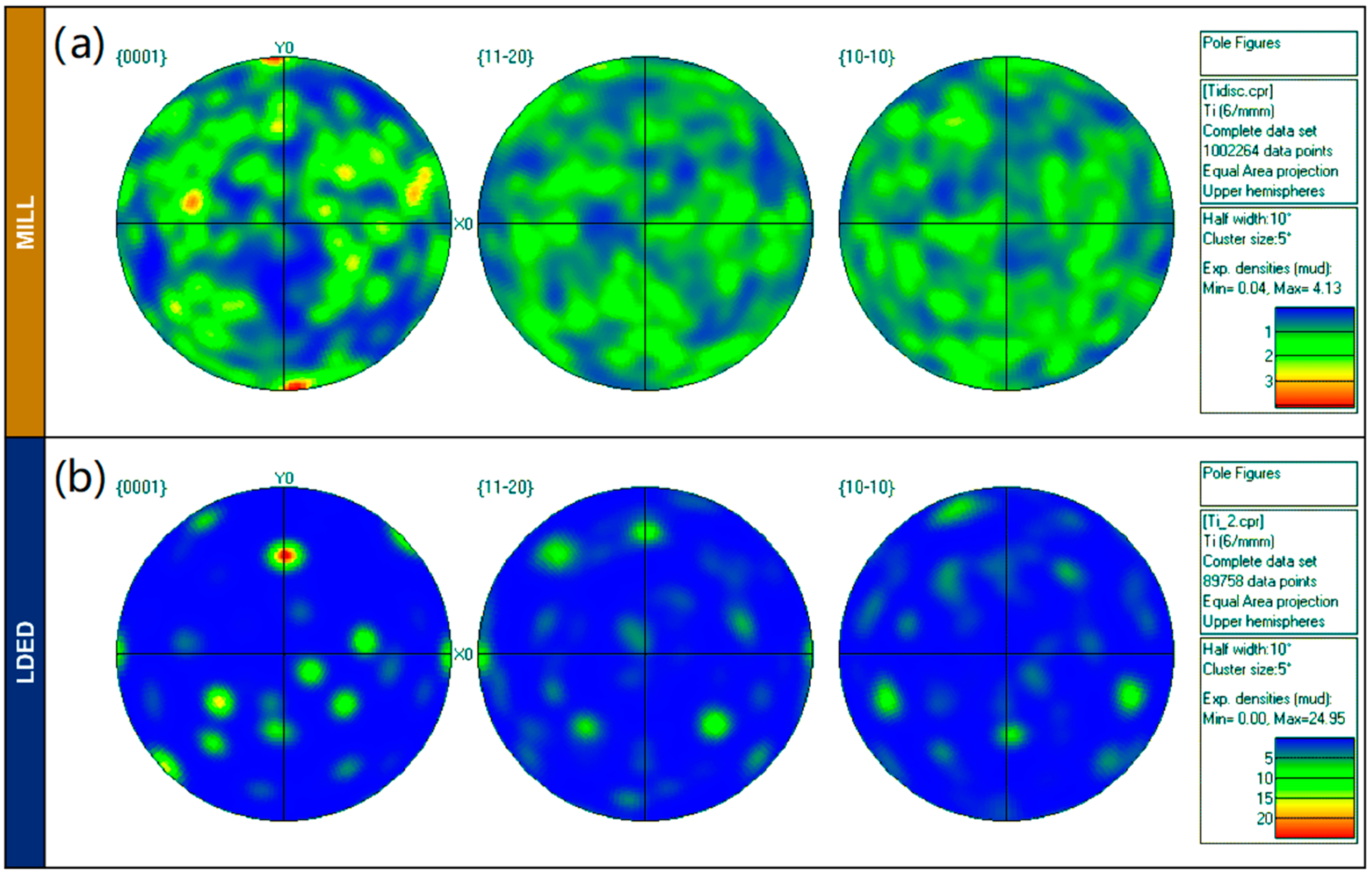
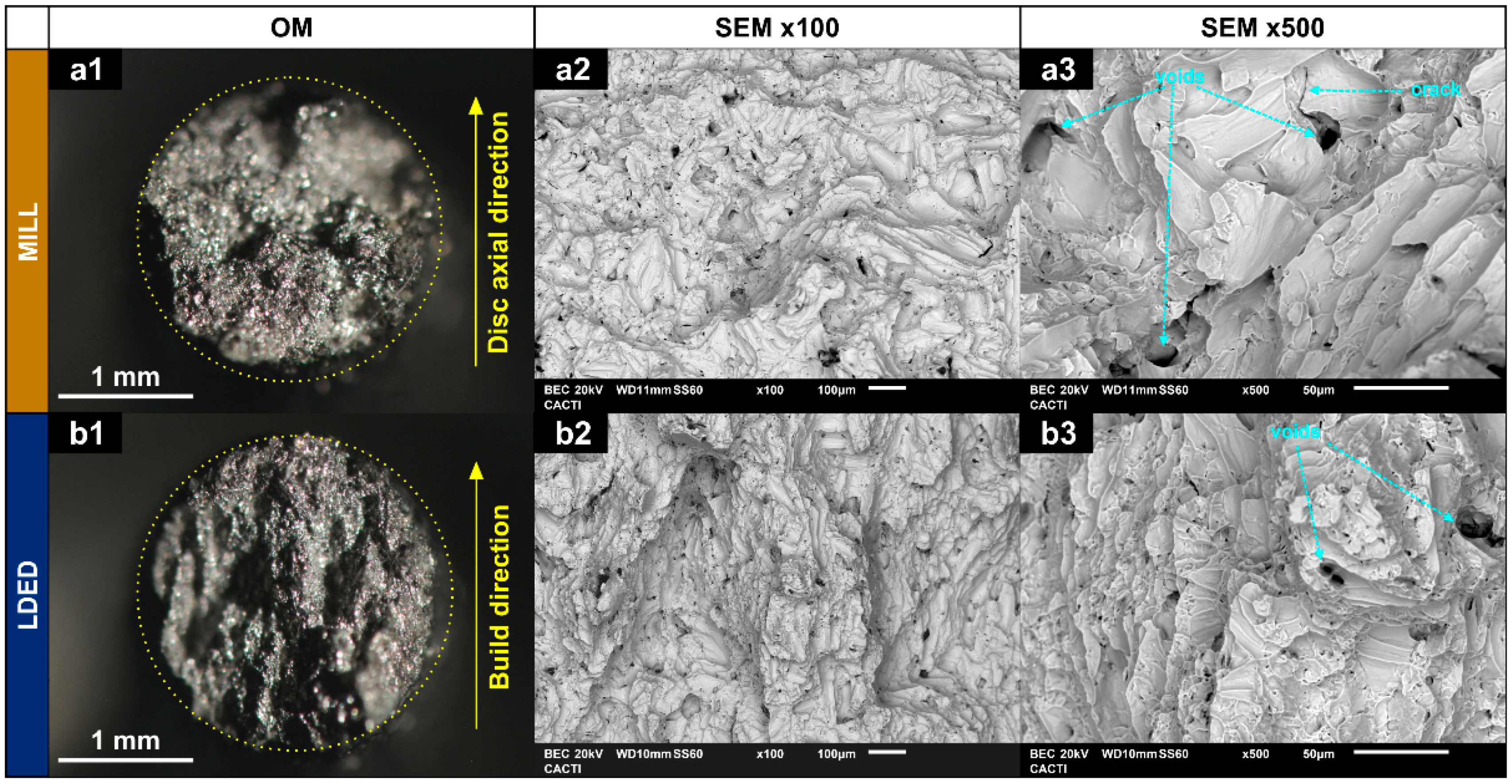
3.1. Microstructural Analysis

SEM images obtained from MILL and LDED samples revealed a clear difference in the microstructure. The MILL alloy shows an equiaxed grain structure, typical of an α-Ti alloy with an annealing process [23] (Figure 3(a1–a3)).
Additionally, some intergranular segregation with higher atomic weight can be observed in the MILL samples. On the other hand, LDED samples show a structure of serrated colonies [31] (Figure 3(b1–b3)), composed of finer lamellar grains with no apparent intergranular segregation. In cp-Ti alloys, serrated colonies are caused by simple cooling from over β-transus temperature with high (but controlled) cooling rates [39], being this microstructure known for having improved mechanical properties in comparison with the equiaxed one [31]. The grain size of this serrated microstructure is dependent on the cooling rate [40]. In this respect, the LDED technique allows the modification of the cooling rate through the selection of processing parameters.
It should be noted that no macro- nor micro-porosity is present in both materials (see Figure 3(a1,b1); Figure 3(a2,b2)). This is of great importance, because in other additive manufacturing techniques, such as selective laser melting (SLM) technique, the porosity is known for being one of the influential factors of detrimental anisotropy in additive manufacturing of cp-Ti materials [41].
In order to evaluate the intergranular segregation, EDS with semi-quantitative analysis and mapping was employed (Figure 4). In the MILL titanium, zone 2 (Figure 4(a2)) showed a higher concentration of Fe than the matrix (Figure 4(a4)) with a quantitative increment in wt % as can be seen in Table 2. In the LDED titanium, the segregation is negligible, and if it existed, could be identified as the small clearer zones in the images (Figure 4(b2)).
However, these clearer zones nearly have the same composition as the matrix as can be seen in Table 2. These segregations are known for being β-Ti zones, stabilized at ambient temperature due to the Fe content, which is a β-eutectoid stabilizer [42]. Also, the presence of them is known for being one of the factors which increases the overall performance of the cp-Ti alloys in comparison with ultra-pure Titanium. These segregations help to reduce the grain size during recrystallization, and therefore improve the yield strength [43].
The XRD analyses clearly show a α-Ti (HCP) structure in both MILL and LDED cases (Figure 5). In cp-Ti alloys, the phase composition is mainly α-Ti (HCP) due to its high stability at room temperature, and only metastable β-Ti (BCC) phase could be found in some Fe-rich segregations. However, given the expected low content of the β phase, the intensity of its peaks is negligible and cannot be observed through XRD.
Differences in XRD peak intensities of both materials suggests a different texture orientation between them [35]. Therefore, EBSD analyses were conducted in order to assess the phase proportion as well as the crystallographic orientation. As can be seen in Figure 6(a2,b2), in accordance with XRD analyses, both materials are composed of α-HCP phase.
On the other hand, Euler and IPFY maps clearly show the difference of grain morphology stated before. The MILL material is composed of equiaxial grains (Figure 6a) and serrated clusters of lamellar grains of the LDED (Figure 6b). In the LDED samples, at higher magnification, these lamellar grains can be better observed in detail (Figure 6(b4)).
In order to correctly evaluate the crystallographic texture, the pole figures (Figure 7) are also presented, showing a notable difference among microstructure orientation distribution. While the MILL alloy has a random orientation of grains (Figure 7a), the LDED titanium is characterized by a limited number of grain orientations (Figure 7b). This limited number of grain orientations is a result of the β to α transformation, from a reduced number of prior β-Ti grains. One β grain parent transforms into α grains with 12 different orientation variants (six without symmetry) due to the Burgers relationship (110)β || (0002)α [42]. It is highly probable that initially at high temperatures the material resulting from LDED had a strong preferred crystallographic texture of β grains, due to the inherent characteristics of the process [35]. However, this initial anisotropy is finally reduced due to the β to α transformation, which redistributes the grain directions in the phase change.
Density of both materials was similar. The MILL cp-Ti had a density of 4.5141 ± 0.0002 g/cm3, whereas the cp-Ti obtained as result of the LDED process had a density of 4.5170 ± 0.0003 g/cm3.

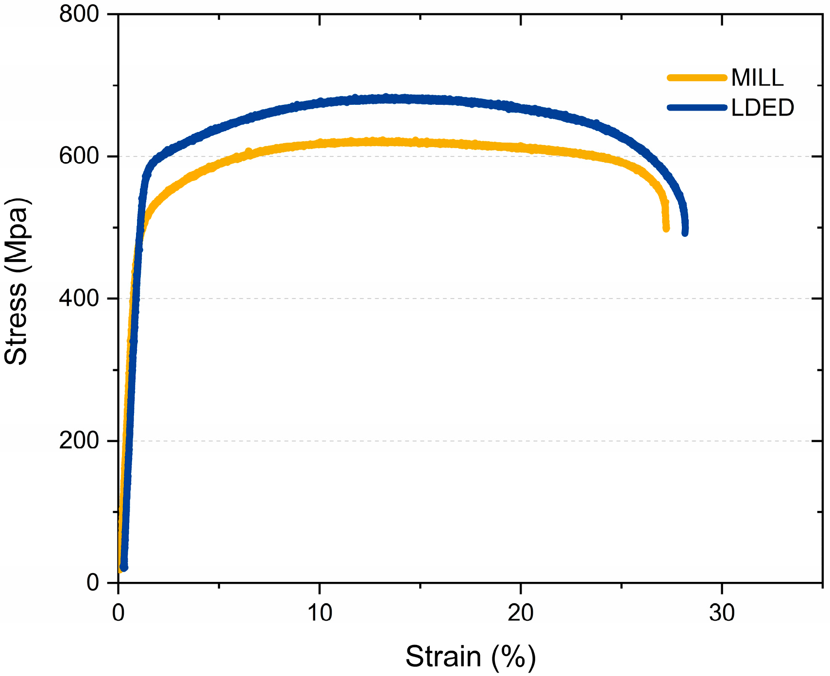
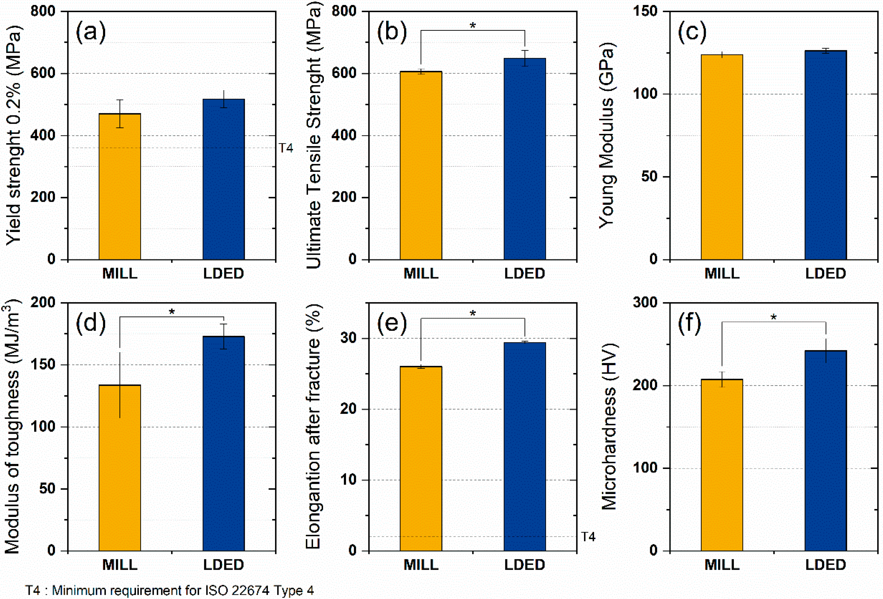
3.2. Mechanical Properties

The mechanical properties of MILL and LDED materials indicate some differences between both techniques. The stress-strain curve (Figure 8) illustrates two representative tensile test from the ones performed. Both materials show a similar behavior, but in the case of the LDED titanium, the curve indicates a slightly better overall performance.
A total of six mechanical properties were studied in order to assess the overall mechanical behavior of MILL and LDED materials. Both alloys show a similar behavior where no significant differences in young modulus (Figure 9c) and yield strength (Figure 9a) were found. However, the LDED material shows a significant increment in UTS (7.0% of increase, Figure 9b), elongation after fracture (12.9% of increase, Figure 9e) and hardness (16.7% of increase, Figure 9f). All these mechanical properties are indicated in the ISO 22674 standard for metallic materials for dentistry. However, all of them gave separate responses of the mechanical performance and do not give a general overview of the behavior of the alloys in real situations, that is why the analysis of the modulus of toughness was performed. The toughness of the material can be defined as the energy per volume it absorbs before breaking, and can be calculated through the integration of the area under the stress–strain curve [44]. The influence of the area under the plastic region on the toughness of the material should be noted, being the reason why ductile materials can absorb more energy than brittle ones. Prostheses are typically designed to maintain stresses within the elastic region. However, a higher modulus of toughness allows an accidental overload keeping the integrity of the material. For dentistry materials, this capability can be the difference between a broken denture and a slight deformation on it.
As can be seen in Figure 9d, LDED shows a higher average modulus of toughness with low dispersion. On the contrary, MILL titanium has a lower toughness value with a greater dispersion on the data, being the difference (30%) between both materials significant (p < 0.05).
Fractography verified these results (Figure 10). Both materials show dimpled fractures typical of ductile materials. Also, the small voids and cracks that appear were probably generated in grain boundaries and segregations [45]. The higher size of the segregations would explain the higher size and less quantity of the voids in the MILL technique (Figure 10(a2,a3)). A recent study in high ductility alloys has associated the reduction in voids size along with a more homogenous distribution of them, with an increment in the ductility of the alloy [46]. Both characteristics are in concordance with the better mechanical properties of the material obtained by LDED, which possess a finer microstructure and therefore, increased overall mechanical properties. Additionally, fractography is also in concordance with EBSD results, indicating that the anisotropy has little effect on mechanical properties, having both materials a similar necking on both X/Y and Z axis (Figure 10(a1,b1)).

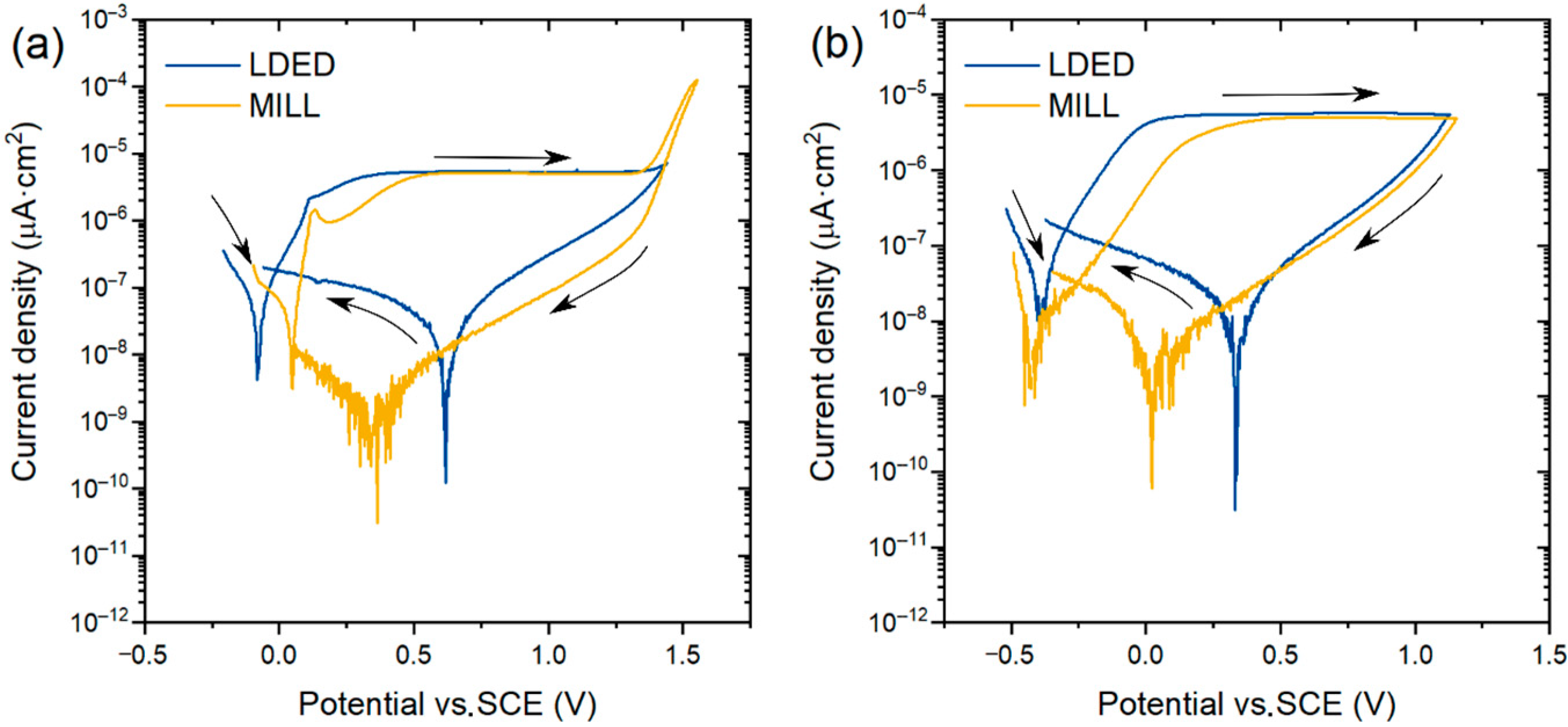
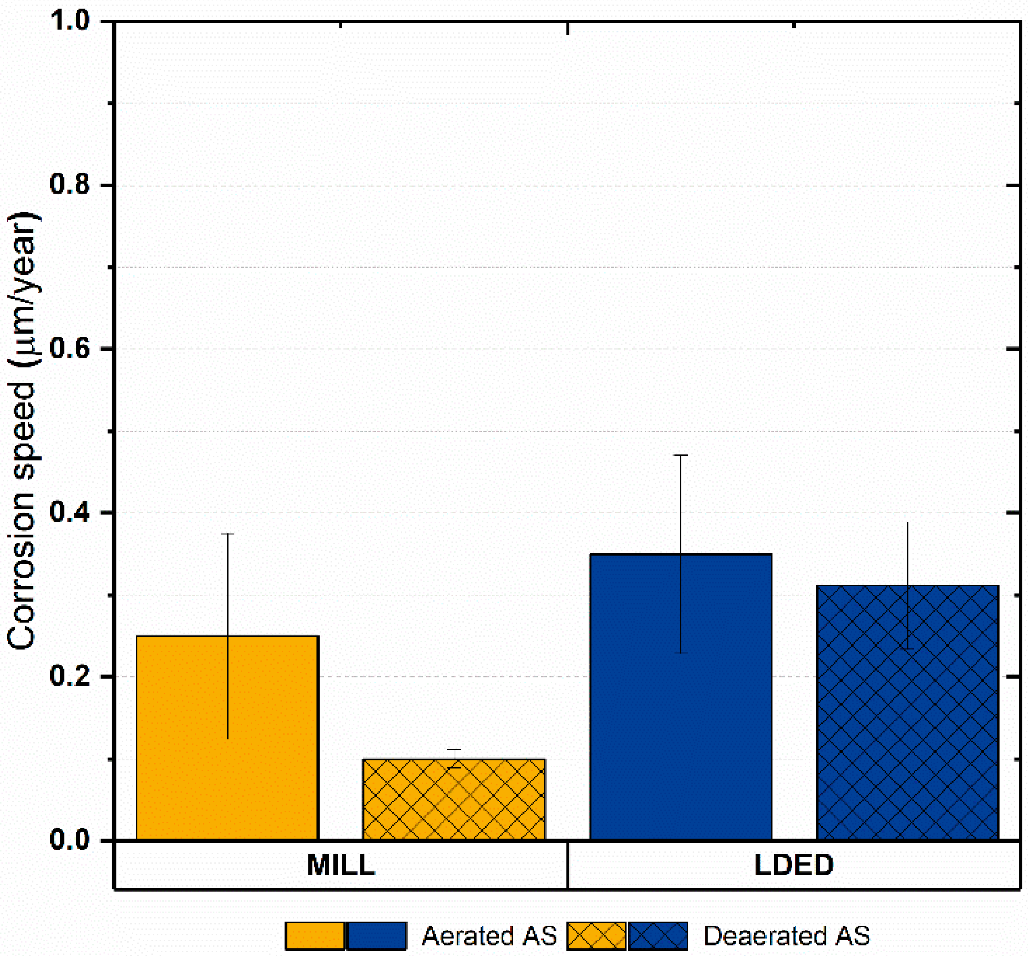
3.3. Electrochemical Properties

Cyclic potentiodynamic polarization (CPDP) analysis was performed to assess the electrochemical properties of both MILL and LDED alloys. These tests were performed in the anodic direction until the electrolysis water potential (around 1.3 V) because at this point the peak of current cannot be attributed to the breakdown potential (Eb) but to the decomposition of water. Then, the potential direction was reversed until corrosion potential (Ecorr). The media employed was aerated AS, in order to assess the corrosion behavior of the buccal environment, as well as deaerated AS to assess the crevice corrosion in zones where the fluid has limited access, such as the gap between implant and abutment.
CPDP curves (Figure 11) of both materials present a similar behavior with a very low current density at corrosion potential (Ecorr). No presence of pitting corrosion was found in both aerated and deaerated media, verified with the negative hysteresis in the reverse scan [47]. Also, the passive layer stability in artificial saliva of the cp-Ti is verified, with a clear horizontal passive zone and no signs of transpassive region. This impressive resistance to corrosion is due to the stable and self-regenerative oxide layer [48] characteristic of the α-Ti alloys [23]. Additionally, the slight reduction of Ecorr in deaerated media can be attributed to the difference of pH from 7.2 (aerated medium) to 8.2 (deaerated medium) caused by the deaeration process and, therefore, decarbonation of the electrolyte.
Additionally, considering that the materials are composed basically of titanium, the corrosion rate was calculated in order to assess the electrochemical results in a more physical approach. As can be seen in Figure 12, the corrosion rate is low in both cases (under 0.4 µm/year) with no significant differences among materials. Another characteristic shared for both materials is that the anodic to cathodic potential in the reverse direction is higher than the original corrosion potential, meaning that the oxide layer is completely stable [49]. Finally, the corrosion speed is lower in deaerated medium for both materials, so the protection against crevice corrosion is also good [50].

4. General Remarks

Commercially pure grade 4 titanium is usually used in biomedical applications by CAD/CAM milling of precursor disks. The results presented here verified the viability of the LDED technique to produce cp-Ti for dental prostheses, confirming that the generated material performs equal or significantly better than the nowadays used MILL technique. Mechanical tests were performed following the ISO 6507-1:2018 and ISO 22674:2016 standards. The latest being the one which classifies the requirements needed for prosthetic dental applications, obtaining both materials the classification of type 4 material, adequate for high stresses applications. Electrochemical properties were also studied following the ISO 10271:2011 standard, which defines the evaluation methods of corrosion for dental metallic materials, with outstanding resistance to corrosion for both materials.
Compositionally, the material employed is cp-Ti grade 4, an alloy that complies with the ISO 5832-2:2012 and ASTM F67 standards of materials for surgical implant applications. The LDED process does not modify the composition of the material, but the microstructure, so the standards compliance is not affected by this manufacturing technique.
Materials resulting from LDED technique presented a higher mechanical performance than the ones resulting from the milling technique: 7% increment of ultimate tensile strength, 12.9% increment of elongation after fracture, and 30% increment of toughness. The main contributor for the improved mechanical properties is the difference of microstructure of the LDED cp-Ti, which has a serrated colonies structure, known for having better mechanical properties [23,43]. These colonies are caused by simple cooling from over β-transus temperature with high (but controlled) cooling rates, instead of annealing process of MILL cp-Ti.
The presence of a higher level of oxygen and Fe-rich phases are known for being a factor of better mechanical properties in cp-Ti. So if the influential factor were the alloying elements, the MILL material would show better mechanical properties than the LDED material.
It should be noted that, even existing significant differences between materials, both of them comply with ISO 22674 standard requirements of type 4 materials for dental restoration applications (yield strength: 360 MPa and elongation after fracture: 2%). Therefore, cp-Ti grade 4 obtained by both MILL and LDED techniques are suitable for their application in dentistry.
For further analysis, biological tests could be performed, but given that the composition is the same, the biocompatibility of the LDED material is still guaranteed.
Finally, the LDED technique possesses advantages of material efficiency and reduces costs in machining (reduced milling time and tool usage, due to the near-net shape obtained parts), giving competitive advantages that can be beneficial in the modern industry.

5. Conclusions

Commercially pure titanium alloy was generated using traditional milling and the novel laser-directed energy deposition (LDED) techniques. cp-Ti obtained by both techniques were investigated to compare their metallographic, mechanical and electrochemical behavior. Dentistry standards, ISO 22674 and ISO 10271, were followed for these tests:
cp-Ti resulting from LDED technique presented a higher mechanical performance than the one resulting from the milling technique: 7% increment of ultimate tensile strength, 12.9% increment of elongation after fracture and 30% increment of toughness. These increments are attributed to differences in the final microstructure: cp-Ti resulting from LDED technique had a serrated colonies structure, whereas the cp-Ti MILL material showed an equiaxial grain microstructure. No significant differences were found with regard to Young modulus, yield strength and density.
Electrochemical performance of both titanium materials was similar with outstanding high resistance to corrosion in artificial saliva, a typical characteristic of commercially pure titanium alloys. The corrosion rate was low in both cases (under 0.4 µm/year) with no significant differences among materials. No presence of pitting corrosion on both LDED and MILL cp-Ti was observed in both aerated and deaerated media.
The LDED technique can be implemented in the manufacturing of titanium for dental restorations with high overall performance. This manufacturing process can compete directly with milling technique and even outperform it. Also, it has the benefits of reduction in material and machining costs, thanks to the near-net shape final form directly obtained from the LDED process.

Author Contributions

F.G.-B. and J.P. designed the work. Ó.B. and F.A.-G. performed all LDED tests. F.L. and J.d.V. analyzed the microstructure of all samples. R.C. and A.B. carried out the evaluation of the mechanical properties of the samples. A.B. and A.R. performed microhardness tests. F.G.-B. and Ó.B. obtained the CAD/CAM milling samples. Ó.B. and R.C. performed all corrosion tests. Ó.B., F.L., and J.P. contributed to write the manuscript with the input from all other authors. All authors have read and agreed to the published version of the manuscript.

Funding

This work was partially supported by the EU research project Bluehuman (EAPA_151/2016 Interreg Atlantic Area), Government of Spain [CLADDENT project _CDTI, RTI2018-095490-J-I00 (MCIU/AEI/FEDER, UE), and by Xunta de Galicia (ED431C 2019/23, ED481D 2017/010, ED481B 2016/047-0).

Data Availability Statement

All data needed to evaluate the conclusions in the paper are present in the paper. Additional data related to this paper may be requested from the authors.

Acknowledgments

The technical staff from CACTI (University of Vigo) and AGACYP (University of Vigo) are gratefully acknowledged.

Conflicts of Interest

Ó.B. and F.G.-B. are linked to the company Corus-Fegoba, manufacturer of dental prosthetic restorations.

References

  1. DebRoy, T.; Wei, H.L.L.; Zuback, J.S.S.; Mukherjee, T.; Elmer, J.W.W.; Milewski, J.O.O.; Beese, A.M.M.; Wilson-Heid, A.; De, A.; Zhang, W. Additive manufacturing of metallic components—Process, structure and properties. Prog. Mater. Sci. 2018, 92, 112–224. [Google Scholar] [CrossRef]
  2. Yang, L.; Hsu, K.; Baughman, B.; Godfrey, D.; Medina, F.; Menon, M.; Wiener, S. Additive Manufacturing of Metals: The Technology, Materials, Design and Production; Springer International Publishing: Cham, Switzerland, 2017; ISBN 978-3-319-55127-2. [Google Scholar]
  3. Bourell, D.; Kruth, J.P.; Leu, M.; Levy, G.; Rosen, D.; Beese, A.M.; Clare, A. Materials for additive manufacturing. CIRP Ann. Manuf. Technol. 2017. [Google Scholar] [CrossRef]
  4. Svetlizky, D.; Zheng, B.; Buta, T.; Zhou, Y.; Golan, O.; Breiman, U.; Haj-Ali, R.; Schoenung, J.M.; Lavernia, E.J.; Eliaz, N. Directed energy deposition of Al 5xxx alloy using Laser Engineered Net Shaping (LENS®). Mater. Des. 2020, 192, 108763. [Google Scholar] [CrossRef]
  5. Zhang, K.; Tian, X.; Bermingham, M.; Rao, J.; Jia, Q.; Zhu, Y.; Wu, X.; Cao, S.; Huang, A. Effects of boron addition on microstructures and mechanical properties of Ti-6Al-4V manufactured by direct laser deposition. Mater. Des. 2019, 184, 108191. [Google Scholar] [CrossRef]
  6. Eo, D.-R.; Park, S.-H.; Cho, J.-W. Inclusion evolution in additive manufactured 316L stainless steel by laser metal deposition process. Mater. Des. 2018, 155, 212–219. [Google Scholar] [CrossRef]
  7. Arias-González, F.; del Val, J.; Comesaña, R.; Penide, J.; Lusquiños, F.; Quintero, F.; Riveiro, A.; Boutinguiza, M.; Pou, J. Fiber laser cladding of nickel-based alloy on cast iron. Appl. Surf. Sci. 2016, 374, 197–205. [Google Scholar] [CrossRef]
  8. Zhong, C.; Gasser, A.; Schopphoven, T.; Poprawe, R. Experimental study of porosity reduction in high deposition-rate Laser Material Deposition. Opt. Laser Technol. 2015, 75, 87–92. [Google Scholar] [CrossRef]
  9. Watkins, K.G.; McMahon, M.A.; Steen, W.M. Microstructure and corrosion properties of laser surface processed aluminium alloys: A review. Mater. Sci. Eng. A 1997, 231, 55–61. [Google Scholar] [CrossRef]
  10. Pei, Y.T.; De Hosson, J.T.M. Functionally graded materials produced by laser cladding. Acta Mater. 2000, 48, 2617–2624. [Google Scholar] [CrossRef] [Green Version]
  11. Verdi, D.; Garrido, M.A.; Múnez, C.J.; Poza, P. Microscale evaluation of laser cladded Inconel 625 exposed at high temperature in air. Mater. Des. 2017, 114, 326–338. [Google Scholar] [CrossRef]
  12. Lusquiños, F.; Pou, J.; Boutinguiza, M.; Quintero, F.; Soto, R.; León, B.; Pérez-Amor, M. Main characteristics of calcium phosphate coatings obtained by laser cladding. Appl. Surf. Sci. 2005, 247, 486–492. [Google Scholar] [CrossRef]
  13. Pou, J.; Lusquiños, F.; Comesaña, R.; Boutinguiza, M. Production of biomaterial coatings by laser-assisted processes. In Advances in Laser Materials Processing; Elsevier: Amsterdam, The Netherlands, 2010; pp. 394–425. ISBN 9781845694746. [Google Scholar]
  14. Arias-González, F.; del Val, J.; Comesaña, R.; Penide, J.; Lusquiños, F.; Quintero, F.; Riveiro, A.; Boutinguiza, M.; Pou, J. Laser cladding of phosphor bronze. Surf. Coatings Technol. 2017, 313, 248–254. [Google Scholar] [CrossRef]
  15. Li, Z.; Chen, J.; Sui, S.; Zhong, C.; Lu, X.; Lin, X. The microstructure evolution and tensile properties of Inconel 718 fabricated by high-deposition-rate laser directed energy deposition. Addit. Manuf. 2020, 31, 100941. [Google Scholar] [CrossRef]
  16. Barro, Ó.; Arias-González, F.; Lusquiños, F.; Comesaña, R.; del Val, J.; Riveiro, A.; Badaoui, A.; Gómez-Baño, F.; Pou, J. Effect of Four Manufacturing Techniques (Casting, Laser Directed Energy Deposition, Milling and Selective Laser Melting) on Microstructural, Mechanical and Electrochemical Properties of Co-Cr Dental Alloys, Before and After PFM Firing Process. Metals 2020, 10, 1291. [Google Scholar] [CrossRef]
  17. del Val, J.; López-Cancelos, R.; Riveiro, A.; Badaoui, A.; Lusquiños, F.; Quintero, F.; Comesaña, R.; Boutinguiza, M.; Pou, J. On the fabrication of bioactive glass implants for bone regeneration by laser assisted rapid prototyping based on laser cladding. Ceram. Int. 2016, 42, 2021–2035. [Google Scholar] [CrossRef]
  18. Denlinger, E.R.; Michaleris, P. Effect of stress relaxation on distortion in additive manufacturing process modeling. Addit. Manuf. 2016, 12, 51–59. [Google Scholar] [CrossRef] [Green Version]
  19. Akram, J.; Chalavadi, P.; Pal, D.; Stucker, B. Understanding grain evolution in additive manufacturing through modeling. Addit. Manuf. 2018, 21, 255–268. [Google Scholar] [CrossRef]
  20. Hsu, H.W.; Lo, Y.L.; Lee, M.H. Vision-based inspection system for cladding height measurement in Direct Energy Deposition (DED). Addit. Manuf. 2019, 27, 372–378. [Google Scholar] [CrossRef]
  21. Li, J.; Zhou, X.; Brochu, M.; Provatas, N.; Zhao, Y.F. Solidification microstructure simulation of Ti-6Al-4V in metal additive manufacturing: A review. Addit. Manuf. 2020, 31, 100989. [Google Scholar] [CrossRef]
  22. Huang, Y.; Ansari, M.; Asgari, H.; Farshidianfar, M.H.; Sarker, D.; Khamesee, M.B.; Toyserkani, E. Rapid prediction of real-time thermal characteristics, solidification parameters and microstructure in laser directed energy deposition (powder-fed additive manufacturing). J. Mater. Process. Technol. 2019, 274, 116286. [Google Scholar] [CrossRef]
  23. Leyens, C.; Peters, M. Titanium and Titanium Alloys; Wiley-VCH: Weinheim, Germany, 2003; ISBN 9783527602117. [Google Scholar]
  24. Radzi, S.; Cowin, G.; Robinson, M.; Pratap, J.; Volp, A.; Schuetz, M.A.; Schmutz, B. Metal artifacts from titanium and steel screws in CT, 1.5T and 3T MR images of the tibial Pilon: A quantitative assessment in 3D. Quant. Imaging Med. Surg. 2014, 4, 163–16372. [Google Scholar] [CrossRef] [PubMed] [Green Version]
  25. Rojo, R.; Prados-Privado, M.; Reinoso, A.; Prados-Frutos, J. Evaluation of Fatigue Behavior in Dental Implants from In Vitro Clinical Tests: A Systematic Review. Metals 2018, 8, 313. [Google Scholar] [CrossRef] [Green Version]
  26. Koizumi, H.; Takeuchi, Y.; Imai, H.; Kawai, T.; Yoneyama, T. Application of titanium and titanium alloys to fixed dental prostheses. J. Prosthodont. Res. 2019, 63, 266–270. [Google Scholar] [CrossRef] [PubMed]
  27. Delgado-Ruiz, R.; Romanos, G. Potential Causes of Titanium Particle and Ion Release in Implant Dentistry: A Systematic Review. Int. J. Mol. Sci. 2018, 19, 3585. [Google Scholar] [CrossRef] [PubMed] [Green Version]
  28. Rincic Mlinaric, M.; Durgo, K.; Katic, V.; Spalj, S. Cytotoxicity and oxidative stress induced by nickel and titanium ions from dental alloys on cells of gastrointestinal tract. Toxicol. Appl. Pharmacol. 2019, 383, 114784. [Google Scholar] [CrossRef]
  29. Niinomi, M. Titanium Alloys. In Encyclopedia of Biomedical Engineering; Elsevier: Amsterdam, The Netherlands, 2019; Volume 5, pp. 213–224. ISBN 9780128012383. [Google Scholar]
  30. Hornberger, H.; Randow, C.; Fleck, C. Fatigue and surface structure of titanium after oxygen diffusion hardening. Mater. Sci. Eng. A 2015, 630, 51–57. [Google Scholar] [CrossRef]
  31. Donachie, M.J. Titanium: A Technical Guide, 2nd ed.; ASM International: Novelty, OH, USA, 2000; Volume 99, ISBN 0-87170-686-5. [Google Scholar]
  32. Na, T.W.; Kim, W.R.; Yang, S.M.; Kwon, O.; Park, J.M.; Kim, G.H.; Jung, K.H.; Lee, C.W.; Park, H.K.; Kim, H.G. Effect of laser power on oxygen and nitrogen concentration of commercially pure titanium manufactured by selective laser melting. Mater. Charact. 2018, 143, 110–117. [Google Scholar] [CrossRef]
  33. Xue, W.; Krishna, B.V.; Bandyopadhyay, A.; Bose, S. Processing and biocompatibility evaluation of laser processed porous titanium. Acta Biomater. 2007, 3, 1007–1018. [Google Scholar] [CrossRef]
  34. Attar, H.; Ehtemam-Haghighi, S.; Kent, D.; Wu, X.; Dargusch, M.S. Comparative study of commercially pure titanium produced by laser engineered net shaping, selective laser melting and casting processes. Mater. Sci. Eng. A 2017, 705, 385–393. [Google Scholar] [CrossRef]
  35. Arias-González, F.; del Val, J.; Comesaña, R.; Penide, J.; Lusquiños, F.; Quintero, F.; Riveiro, A.; Boutinguiza, M.; Gil, F.J.; Pou, J. Microstructure and crystallographic texture of pure titanium parts generated by laser additive manufacturing. Met. Mater. Int. 2018, 24, 231–239. [Google Scholar] [CrossRef]
  36. Attar, H.; Bermingham, M.J.; Ehtemam-Haghighi, S.; Dehghan-Manshadi, A.; Kent, D.; Dargusch, M.S. Evaluation of the mechanical and wear properties of titanium produced by three different additive manufacturing methods for biomedical application. Mater. Sci. Eng. A 2019, 760, 339–345. [Google Scholar] [CrossRef]
  37. Amado, J.M.; Rodríguez, A.; Montero, J.N.; Tobar, M.J.; Yáñez, A. A comparison of laser deposition of commercially pure titanium using gas atomized or Ti sponge powders. Surf. Coatings Technol. 2019, 374, 253–263. [Google Scholar] [CrossRef]
  38. de Terris, T.; Andreau, O.; Peyre, P.; Adamski, F.; Koutiri, I.; Gorny, C.; Dupuy, C. Optimization and comparison of porosity rate measurement methods of Selective Laser Melted metallic parts. Addit. Manuf. 2019, 28, 802–813. [Google Scholar] [CrossRef]
  39. Oh, M.S.; Lee, J.Y.; Park, J.K. Continuous cooling β-to-α transformation behaviors of extra-pure and commercially pure Ti. Metall. Mater. Trans. A Phys. Metall. Mater. Sci. 2004, 35 A, 3071–3077. [Google Scholar] [CrossRef]
  40. Kim, S.K.; Park, J.K. In-situ measurement of continuous cooling β → α transformation behavior of CP-Ti. Metall. Mater. Trans. A Phys. Metall. Mater. Sci. 2002, 33, 1051–1056. [Google Scholar] [CrossRef]
  41. Wysocki, B.; Maj, P.; Krawczyńska, A.; Rożniatowski, K.; Zdunek, J.; Kurzydłowski, K.J.; Święszkowski, W. Microstructure and mechanical properties investigation of CP titanium processed by selective laser melting (SLM). J. Mater. Process. Technol. 2017, 241, 13–23. [Google Scholar] [CrossRef]
  42. Lütjering, G.; Williams, J.C. Titanium, 2nd ed.; Derby, B., Ed.; Springer: Berlin, Germany, 2007; ISBN 978-3-540-71397-5. [Google Scholar]
  43. Conrad, H. Effect of interstitial solutes on the strength and ductility of titanium. Prog. Mater. Sci. 1981, 26, 123–403. [Google Scholar] [CrossRef]
  44. Tobolski, E.L.; Fee, A. ASM Handbook, Volume 8: Mechanical Testing and Evaluation; ASM International: Materials Park, OH, USA, 2000; ISBN 0-87170-389-0. [Google Scholar]
  45. ASM Handbook Committee. Fractography; ASM International: Materials Park, OH, USA, 1987; ISBN 978-1-62708-181-8. [Google Scholar]
  46. Shang, X.; Zhang, H.; Cui, Z.; Fu, M.W.; Shao, J. A multiscale investigation into the effect of grain size on void evolution and ductile fracture: Experiments and crystal plasticity modeling. Int. J. Plast. 2020, 125, 133–149. [Google Scholar] [CrossRef]
  47. Esmailzadeh, S.; Aliofkhazraei, M.; Sarlak, H. Interpretation of Cyclic Potentiodynamic Polarization Test Results for Study of Corrosion Behavior of Metals: A Review. Prot. Met. Phys. Chem. Surfaces 2018, 54, 976–989. [Google Scholar] [CrossRef]
  48. Cramer, S.D.; Covino, B.S., Jr. ASM Handbook Volume 13B: Corrosion: Materials; ASM International: Materials Park, OH, USA, 2005; Volume 13, ISBN 087170708X. [Google Scholar]
  49. Diaz, I.; Martinez-Lerma, J.F.; Montoya, R.; Llorente, I.; Escudero, M.L.; García-Alonso, M.C. Study of overall and local electrochemical responses of oxide films grown on CoCr alloy under biological environments. Bioelectrochemistry 2017, 115, 1–10. [Google Scholar] [CrossRef] [Green Version]
  50. Schweitzer, P.A. Fundamentals of Corrosion-Mechanisms, Causes, and Preventative Methods; CRC Press: Boca Raton, FL, USA, 2013; Volume 53, ISBN 9788578110796. [Google Scholar]
Figure 1. Outline of the LDED (laser-directed energy deposition) technique with coaxial particle injection set-up. Detail of the interaction zone showing the convergence of the laser beam and powder particles into the molten pool under an inert protective atmosphere.
Metals 11 00070 g001
Figure 2. (a): Tridimensional representation of the scanning strategy of the LDED samples. (b): Specimens milled from the generated cuboids.
Metals 11 00070 g002
Figure 3. Optical images (a1,b1) and backscattered SEM micrographs (a2,a3,b2,b3) of a longitudinal section of MILL (a1a3) and LDED (b1b3) samples.
Metals 11 00070 g003
Figure 4. SEM micrographs (a1,a2,b1,b2) and EDS mapping for Ti (a3,b3) and Fe (a4,b4) for MILL (a1a4) and LDED (b1b4) materials.
Metals 11 00070 g004
Figure 5. X-ray diffraction patterns of MILL (a) and LDED (b) materials.
Metals 11 00070 g005
Figure 6. EBSD images of band contrast (a1,b1), phase maps (a2,b2), Euler color maps (a3,b3,a4,b4) and IPFY maps (a5,b5) for both MILL (a1a5) and LDED (b1b5) materials.
Metals 11 00070 g006
Figure 7. (a): EBSD pole figures for MILL. (b): EBDS pole figures for LDED materials.
Metals 11 00070 g007
Figure 8. Representative stress strain curves of both MILL and LDED materials.
Metals 11 00070 g008
Figure 9. Mechanical properties of MILL and LDED materials: yield strength (a), ultimate tensile strength (b), Young’s modulus (c), modulus of toughness (d), elongation after fracture (e), and microhardness (f). Error bars indicate the standard deviation. Asterisks (*) mean a level of significance p < 0.05.
Metals 11 00070 g009
Figure 10. Fractography images of breaking surface. (a1,b1): optical microscopy; (a2,a3,b2,b3): BSE SEM microscopy.
Metals 11 00070 g010
Figure 11. Representative cyclic potentiodynamic polarization curves of both MILL and LDED samples. (a): curves obtained into aerated artificial saliva media; (b) curves obtained into deaerated artificial saliva media.
Metals 11 00070 g011
Figure 12. Bar graphs of equivalent corrosion rate (Ti) in aerated and deaerated artificial saliva. Error bars indicate the standard deviation.
Metals 11 00070 g012
Table 1. Chemical composition (wt %) of the alloys tested in the present study with standards limitations for grade 4 titanium. Data provided by the manufacturers.
Brand NameManufacturerTiFeONCHUsed in Technique
ISO 5832-2:2012Grade 4 max. limitBal0.500.400.050.080.0125-
ASTM F67Grade 4 max. limitBal0.500.40 0.015-
Eutitan grade 4Schütz Dental GmbH, Velbert, GermanyBal0.2590.280.0080.0160.001MILL
Metco 4010AOerlikon Metco Europe GmbH, Kelsterbach, GermanyBal0.010.100.000.010.007LDED
Table 2. Chemical composition (wt %) of the matrix (1) and segregation zone (2) determined by semi-quantitative EDS analysis.
ProcessZoneTiFeONC
MILL193.990.083.340.002.60
284.836.955.450.002.77
LDED193.070.004.240.002.69
293.340.123.620.192.74
Note: Zones 1 and 2 correspond to those indicated in Figure 4.
Publisher’s Note: MDPI stays neutral with regard to jurisdictional claims in published maps and institutional affiliations.

