
Abstract
The purpose of this paper is to give an interpretation to the fringes observed in holographic interferometry when plane-polarized light or circularly polarized light is utilized. It is shown that, when plane-polarized light is utilized and both the loaded and the unloaded states are considered, the obtained patterns are formed by the superposition of three families of fringes: the two families of absolute optical retardation and the family of relative retardation. The intensity distribution is also a function of the orientation of the plane of polarization, and along the points where the plane of polarization is parallel to one of the principal directions, only one of the families of absolute retardation is observed. By utilizing circularly polarized light, the dependence on the orientation of the principal axis is eliminated and patterns consisting of the superposition of the three above-mentioned families are obtained. If only the loaded state is considered, the holographic interferometer behaves as an ordinary polariscope with the reference beam playing the role of the analyzer. The relationships between the observed families are discussed. Examples of application to the disk and ring under diametral compression are also given.
Abbreviations
- a :
-
stress-optical constant
- \(\bar a\) :
-
\(stress - optical constant = \frac{a}{{(a^2 - b^2 )h}}\)
- A R :
-
complex representation of the reconstructed first order wavefront (scalar wave)
- b :
-
stress-optical constant
- \(\bar b\) :
-
\(stress - optical constant = \frac{b}{{(a^2 - b^2 )h}}\)
- c :
-
cos β
- E 1 :
-
exposure=I·t, first exposure
- E 2 :
-
same, second exposure
- h :
-
thickness of the unloaded model
- h′:
-
thickness of the loaded model
- I 1 :
-
light intensity, first exposure
- I R :
-
light intensity of the first order in the reconstruction
- I PL :
-
light intensity in the reconstructed image, plane-polarized light, bright background
- I PD :
-
light intensity in the reconstructed image, plane-polarized light, dark background
- I CL :
-
light intensity in the reconstructed image, circularly polarized light, bright background
- I CD :
-
light intensity in the reconstructed image, circularly polarized light, dark background
- k :
-
\(\frac{{2\pi }}{\lambda }\)
- K :
-
\(ratio of the exposure times = \frac{{t_1 }}{{t_2 }}\)
- k 1,k 2 :
-
parameters
- M :
-
constant of proportionality
- n o :
-
index of refraction of the model in the unloaded condition
- n 1,n 2 :
-
principal indexes of refraction
- R :
-
complex representation of the reconstruction wavefront
- R :
-
amplitude modulus of the reconstruction wavefront
- s :
-
sin β
- S :
-
\(R^2 \in 1^2 \in R^2\)
- t 1,t 2 :
-
exposure times, first and second exposures respectively
- T :
-
transmission function of the holographic plate
- γ:
-
slope of the straight-line portion of the plot density vs. the logarithm of the exposure
- \(\delta _1\) :
-
absolute variation of the optical path of the polarized component vibrating parallel to the principal direction 1
- \(\delta _2\) :
-
same, with respect to the direction 2
- \(\delta _3\) :
-
difference between the absolute variation of the optical paths 1 and 2
- \(\varepsilon 1\) :
-
object wavefront during the first exposure (vector wave) primed →x′,y′,z′ unprimed →x,y,z;
- \(\varepsilon 2\) :
-
same, during the second exposure
- \(\varepsilon R\) :
-
reference wavefront
- \(\varepsilon 1T,\varepsilon 2T\) :
-
total light vectors, first and second exposure respectively
- \(\bar \varepsilon\) :
-
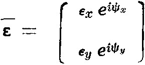
complex amplitude vectors primed →x′, y′, z′ unprimed →x, y, z
- \(\varepsilon _x ,\varepsilon _y\) :
-
scalar components of the complex amplitude vectors
- \(\varepsilon R, \varepsilon 1, \varepsilon 2\) :
-
modulus of the reference wavefront, the object wavefront (first exposure), the object wavefront (second exposure).\(\varepsilon = \sqrt {\varepsilon _{x^2 } + \varepsilon _{y^2 } }\)
- \(\psi x, \psi y\) :
-
phases of the components of the amplitude vector
- θ:
-
angle of inclination of the reference and object wavefronts with respect to the plane of the hologram
- λ:
-
wavelength of the light
- \(\sigma _1 ,\sigma _2\) :
-
principal stresses
- ψ:
-
phase change introduced by the unloaded model
- \(\psi _1\) :
-
change of phase introduced by the loaded model in the principal direction 1
- \(\psi _2\) :
-
same, in the principal direction 2
- ω:
-
angular frequency of the light

References
Rodgers, G. L., “Polarization Effects in Holography,” Jnl. of the Optical Society of America (1966).
Hovanesian, J. D., Brcic, V. and Powell, R., “A New Stress-Optic Method, Stress-Holo-Interferometry,” Tehnika (November 1967).
Fourney, M. E. “Application of Holography to Photoelasticity,”Experimental Mechanics,8 (1),33–38 (1968).
Manojaran, D. and Sevigny, L., “Polarization Holography,” Jnl. of the Optical Society of America,56 (1967).
Bryngdahl, O., “Polarizing Holography,” Jnl. of the Optical Society of America,57 (1967).
Fourney, M. E., Waggoner, A. P. and Mate, K. V., “Recording Polarization Effects via Holography,” Jnl. of the Optical Society of America,58 (1968).
Lohman, A. W., “Reconstruction of Vectorial Wavefronts,” Applied Optics,4 (1965).
Nicolas, J., “Sur la Déterminatior. de la Somme des Contraintes Principales au Moyen de L’Interferometrie Holographique,” Comptes Rendus de L’Academie des Sciences, t. 267, Serie A (1968).
Hovanesian, J. D., Brcic, V. andPowell, R. L., “A New Experimental Stress-Optic Method: Stress-Holo-Interferometry,”Experimental Mechanics,8 (8),362–368 (1968).
Powell, R. L., Hovanesian, J. D. and V. Brcic, “Hologram Interferometry with Birefringent Objects.” The Engineering Uses of Holography. Proceedings of the Conference held at the University of Strathclyde (September 1968).
Hovanesian, J. D., “Interference of Two and Three Reconstructed Waves in Photoelasticity,”U. S. Navy Journal of Underwater Acoustics,18 (4) (October 1968).
Kezin, G. L., Sakharov and Zhavozonov, “The Use of Holography in Investigations of Hydraulic Equipment by the Photoelastic Method,” Ency. Stroit 7 (97) (1969).
Holoway, D. C., “Holography and its Application to Photoelasticity,”T and M Report No. 329, University of Illinois, Urbana, Ill. (June 1969).
Fourney, M. E. andMate, K. V. “Further Applications of Holography to Photoelasticity,”Experimental Mechanics,10 (5),177–186 (1970).
Hosp, V. E. andWutze, G. “The Application of Holography in Plane Photoelasticity,”Materialprüfung Bd. 11 (12)S. 409–415 (1969).
Hosp, V. E. andWutze, G., “Holographic Determination of the Principal Stresses in Plane Models,”Materialprüfung Bd. 12 (1)S. 13–22 (1970).
Sanford, R. J. andDurelli, A. J., “The Interpretation of Fringes in Stress-Holo-Interferometry,”Experimental Mechanics,11 (4),161–166 (1971).
Post, D. “The Generic Nature of the Absolute-retardation Method in Photoelasticity,”Experimental Mechanics,7 (6),233–241 (1967).
Nisida, M. andSaito, H., “A New Interferomatic Method of Two-dimensional Stress Analysis,”Experimental Mechanics,4 (12),366–376 (1964).
Favre, H., “Sur une Nouvelle Méthode Optique de Détermination des Tensions Interieures,”Tesis, Polytechnic Institute of Zurich, Revue Opt.,8,193,241, 289 (1929).
Sciammarella, C. A., Doddington, C. W., “Effect of Photographic Film Nonlinearities on the Processing of Moiré Fringe Data,”Experimental Mechanics,7 (9),398–402 (1967).
Sciammarella, C. A. and Palacio, M., “Photoelastic Test of a Deep Beam,”Ciecia y Tecnica 113 (569) (1949).
Author information
Authors and Affiliations
Rights and permissions
About this article
Cite this article
Sciammarella, C.A., Quintanilla, G. Techniques for the determination of absolute retardation in photoelasticity. Experimental Mechanics 12, 57–66 (1972). https://doi.org/10.1007/BF02408440
Received:
Revised:
Issue Date:
DOI: https://doi.org/10.1007/BF02408440