
Abstract
Satellite laser ranging (SLR) to the satellites of the global navigation satellite systems (GNSS) provides substantial and valuable information about the accuracy and quality of GNSS orbits and allows for the SLR-GNSS co-location in space. In the framework of the NAVSTAR-SLR experiment two GPS satellites of Block-IIA were equipped with laser retroreflector arrays (LRAs), whereas all satellites of the GLONASS system are equipped with LRAs in an operational mode. We summarize the outcome of the NAVSTAR-SLR experiment by processing 20 years of SLR observations to GPS and 12 years of SLR observations to GLONASS satellites using the reprocessed microwave orbits provided by the center for orbit determination in Europe (CODE). The dependency of the SLR residuals on the size, shape, and number of corner cubes in LRAs is studied. We show that the mean SLR residuals and the RMS of residuals depend on the coating of the LRAs and the block or type of GNSS satellites. The SLR mean residuals are also a function of the equipment used at SLR stations including the single-photon and multi-photon detection modes. We also show that the SLR observations to GNSS satellites are important to validate GNSS orbits and to assess deficiencies in the solar radiation pressure models. We found that the satellite signature effect, which is defined as a spread of optical pulse signals due to reflection from multiple reflectors, causes the variations of mean SLR residuals of up to 15 mm between the observations at nadir angles of 0\(^{\circ }\) and 14\(^{\circ }\). in case of multi-photon SLR stations. For single-photon SLR stations this effect does not exceed 1 mm. When using the new empirical CODE orbit model (ECOM), the SLR mean residual falls into the range 0.1–1.8 mm for high-performing single-photon SLR stations observing GLONASS-M satellites with uncoated corner cubes. For best-performing multi-photon stations the mean SLR residuals are between \(-12.2\) and \(-25.6\) mm due to the satellite signature effect.
1 Introduction
1.1 Role of SLR and GNSS in space geodesy
Satellite laser ranging (SLR) observations of global navigation satellite systems (GNSS) become more and more important for satellite geodesy by providing a precise link in space between the two techniques. The strengths of SLR and GNSS solutions are different for different geophysical phenomena and for the realization of the geodetic reference frames. SLR contributes to certain datum parameters of the reference frame, i.e., to the origin and the scale. The advantage of the SLR technique lies in the observation principle based on short laser pulses with fast rise-times, resulting in a tracking precision at a level of a few millimeters. Laser range observations are free from many propagation issues related, e.g., to ionosphere delays, microwave antenna phase center variations, or phase ambiguities. Moreover, SLR observations to geodetic satellites take full advantage of a simple construction of passive satellites. Geodetic SLR satellites are dense and have spherical shapes and small area-to-mass ratio, which also minimizes orbit perturbations related to non-gravitational forces, e.g., atmospheric drag and solar radiation pressure.
When analyzing GNSS microwave observations, modeling problems related to the uncalibrated satellite antenna phase center offsets are a major error source for the scale (Thaller et al. 2014), whereas the deficiencies in solar radiation pressure modeling affect the GNSS-derived geocenter series, in particular the \(Z\) component (Meindl et al. 2013). On the other hand, the global distribution of the GNSS stations is nowadays homogeneous with a high density of observing stations, as opposed to the SLR network with merely seven observing stations in the southern hemisphere. Moreover, the Earth rotation parameters derived from GNSS and the horizontal components of station coordinates are superior to the SLR-derived values (Thaller et al. 2011). GNSS solutions are crucial for the densification of the international terrestrial reference frame (ITRF) to regional and national reference frames. The high consistency and a good connection between SLR and GNSS are, thus, indispensable.
The International Laser Ranging Service (ILRS, Pearlman et al. 2002) coordinates all operational and scientific activities of the institutions involved in scientific satellite and lunar laser ranging since 1998 (Gurtner et al. 2005). The Center for Orbit Determination (CODE), hosted by the Astronomical Institute of the University of Bern (AIUB) is one of the ILRS associated analysis centers. CODE provides the GNSS quick-look residual analysis reports on a daily basis, which compare the SLR observations to GLONASS and GPS satellites with the microwave orbits. The reports assess thus the consistency level between GNSS and SLR solutions.
1.2 GNSS satellites tracked by SLR
In the NAVSTAR-SLR experiment two GPS satellites of Block-IIA were equipped with laser retroreflector arrays (LRAs) dedicated to SLR, namely GPS-36 launched on March 10, 1994 and GPS-35 launched on August 30, 1993. GPS-36 was observed continuously by SLR stations between 1994 and 2014. The satellite was deactivated in February 2014.Footnote 1 GPS-35 was continuously observed until 2009, when the satellite was decommissioned. Between 2010 and 2013 GPS-35 was reactivated several times for short periods. In 2011 the ILRS decided to remove this satellite from the official list of tracked satellites. Afterwards, only one SLR station, Zimmerwald, continued to track GPS-35 in 2012–2013 with SLR.
The basic objectives of the NAVSTAR-SLR experiment were the accurate independent orbit determination of the satellites and the separation of the orbital errors from the on-board clock errors (Beard 2014).
As opposed to the GPS system, all satellites of the Russian GLONASS, the European Galileo, and the Chinese BeiDou are equipped with laser retroreflectors. It is also planned that the GPS-III satellites will carry laser retroreflectors in the future (Thomas and Merkovitz 2014).
Although all GLONASS satellites are equipped with SLR retroreflectors, only three GLONASS satellites were recommended for tracking by the ILRS in the period of 2002–2010—typically one satellite per plane. In 2010 the ILRS decided to increase the number of officially-tracked GLONASS satellites to six—two per plane. Exceeding the ILRS recommendations, several of the more able SLR stations started tracking the full constellation of GLONASS in 2010–2011. The first station tracking the full GLONASS constellation was Herstmonceux (Wilkinson 2012; Appleby 2013), followed by Zimmerwald (Ploner et al. 2012), Graz, Yarragadee, Potsdam, Changchun, Shanghai, Simeiz, Altay, Arkhyz, and some other ILRS stations.
Today, all active GLONASS satellites are tracked by many SLR stations. This results in a very good tracking record of different GNSS satellites, which allows us to validate the GNSS microwave orbits (Zhu et al. 1997; Appleby et al. 1999; Urschl et al. 2007; Fritsche et al. 2014; Montenbruck et al. 2015, Steigenberger et al. 2015), to generate precise satellite orbits using SLR data (e.g., Rodriguez and Appleby 2013), and to combine SLR and GNSS techniques using the co-locations in space. The space co-locations allow, e.g., improving the quality of the GNSS orbits, estimating the satellite microwave antenna offsets, and the scale transfer from the SLR to GNSS solutions (Thaller et al. 2011, 2012a, b). The satellite co-locations are independent of the local ties on ground, which are often affected by systematic errors (Altamimi et al. 2011). Moreover, the increasing number of SLR observations to GNSS satellites will strengthen, in the near future, the realization of the international terrestrial reference system (ITRS) due to better established SLR station coordinates and improved observation geometry in SLR solutions.
1.3 Increasing importance of SLR to the improvement of GNSS solutions
The 18th international workshop on laser ranging, which was held in Fujiyoshida (Japan) in November 2013,Footnote 2 recognized the “increasing importance of SLR to the improvement of GNSS performance”. The resolution of the workshop paid special attention to “the necessity of the SLR technique to the improvement of time, frequency, and ephemeris data products from GNSS” and to “the significant contribution of the global geodetic observing system (GGOS) to the development of GNSS measurement accuracy through co-location with SLR and other measurement techniques”. The laser ranging to GNSS s/c experiment (LARGE) group was established in the aftermath of this workshop as an official study group of the ILRS.Footnote 3 The primary objectives of the LARGE group include a definition of an operational GNSS tracking strategy for the ILRS and improving the consistency between products provided by the ILRS and the International GNSS Service (IGS, Dow et al. 2009).
1.4 Goal of this study
The future realization of the ITRF will probably comprise also SLR observations of GNSS satellites. This paper summarizes the results of the NAVSTAR-SLR experiment and the outcome from the campaign of intensive SLR tracking of GLONASS satellites as a preparation for the future ITRF. We process 20 years of SLR observations to GPS and 12 years of SLR observations to GLONASS satellites using the reprocessed microwave orbits provided by CODE. The solution strategy in this paper is similar to that of the daily CODE quick-look residual analysis reports. We investigate the SLR residuals to GPS and GLONASS microwave orbits without estimating any parameters. This study provides thus the information about the consistency between SLR and GNSS solutions and about the SLR efficiency for the quality assessment of GNSS orbits.
2 Method of analysis
2.1 GNSS solutions
We use GPS and GLONASS orbits determined in the second IGS reprocessing campaign for the preparation of the ITRF2014. The CODE solutions follow the IGS requirements for reprocessed IGS products,Footnote 4 including the use of the IERS Conventions 2010 (Petit and Luzum 2011) for mean pole definition and tidal displacements, the IGb08 reference frame with updated absolute antenna calibrations, and the use of higher-order ionospheric corrections from the IERS Conventions, and Earth radiation pressure modeling by Rodriguez-Solano et al. (2012). The block-dependent transmitter thrust values were used for the GPS satellites, whereas for all GLONASS satellites a thrust assumption of 100 W was applied. The CODE solutions were based on GPS-only observations in 1994–2001 and on combined GPS and GLONASS observations in 2002–2013. The GNSS stations tracking only GLONASS satellites were not used in the analysis. The solution was generated with the development version of Bernese GNSS Software v. 5.3 (Dach et al. 2007).
The orbit parameterization included 6 Keplerian elements. No a priori radiation pressure model was applied. Five empirical parameters of the empirical CODE orbit model (ECOM, Beutler et al. 1994) were estimated:
-
a constant acceleration in the Sun direction \(D_0\),
-
a constant acceleration along the axis of the satellites’ solar panels \(Y_0\),
-
a constant and two once-per-revolution accelerations in the direction \(X\): \(X_0, X_S. X_C\). The \(X\) direction completes right-handed coordinate system.
The once-per-revolution accelerations in the \(D\) and \(Y\) directions were also estimated, but they were constrained to zero with a sigma of \(10^{-12}\) m s\(^{-2}\). Pseudo-stochastic pulses (small velocity changes) were estimated every 12 h in three orthogonal orbit directions (radial, along-track, out-of-plane). The static a priori gravity field model is used with no temporal variability induced by the atmosphere, oceans, nor hydrology. The impact of station displacements caused by the non-tidal atmospheric loading was excluded by constraining the scaling factor of this effect to zero. A detailed description of the reprocessing solutions can be found in the CODE analysis strategy summary for the second IGS reprocessing campaign.Footnote 5
As opposed to other analysis centers, CODE provided two solutions for the IGS repro2 campaign: clean one-day solutions (CF2) and the three-day long-arc solutions (CO2) with the satellite orbits and Earth rotation parameters referring always to the middle day of 3-day satellite arcs. Both solutions are validated in our analysis.
Two different models of solar radiation pressure are tested in Sect. 5: the classical ECOM and the extended ECOM which is used for operational CODE IGS products since January 2015. A test based on 2-year solutions is performed to demonstrate the SLR potential for validating and assessing the quality of the microwave-based orbits of GNSS satellites.
2.2 SLR solutions
The SLR range residuals are computed as differences between laser ranges and the microwave-based positions of GNSS satellites. The consistent GNSS-derived Earth rotation parameters from the CO2 or CF2 solutions are used for the transformation between the Earth-fixed and inertial reference frames. The station coordinates are fixed to the a priori reference frame SLRF2008.Footnote 6 The SLR observations are corrected for relativistic effects, troposphere delays, and for the offset of the LRAs w.r.t. the satellites’ centers of mass. The official ILRS values of LRA offsets are usedFootnote 7 without any time dependencies. The a priori range bias corrections are applied as recommended by the Analysis Working Group of the ILRS for the ITRF2014 reprocessing of LAGEOS and Etalon data.Footnote 8 The station displacement models, including solid Earth tides, ocean tidal loading, and non-tidal station displacements are consistent with the IERS Conventions 2010 and thus also with the microwave-based GNSS solutions. Moreover, the same version 5.3 of the Bernese GNSS Software is used to ensure a full consistency between GNSS and SLR solutions. The SLR residuals constitute good proxies for the radial accuracy of the microwave-derived orbits, because the maximum angle of incidence of a laser pulse is only about \(13^\circ \) and \(14^\circ \) for GPS and GLONASS satellites, respectively.
Almost every SLR station has a different technology, including different detectors, using different laser pulse widths, laser repetition rates, and edit levels for the normal point formation. This broad spectrum of uniquely developed stations impacts upon the different qualities of data provided.
Because of the differences in quality and quantity of SLR observations, we apply a two-step procedure of SLR data screening: In the first step, only the largest outliers of hundreds of meters are removed. Then we perform an analysis of 20 years of SLR data with the estimation of the mean value of SLR residuals w.r.t. GNSS microwave-based orbits and the RMS of residuals for each individual station-satellite pair. RMS denotes here a standard deviation of SLR residuals around mean value, without removing any systematic effects. In the second step of the residual screening, we reject all observations exceeding the threshold: mean \(\pm 3 \cdot \) RMS. In this way we avoid a removal of the observations with small RMS values but large biases to GNSS satellites in our analysis. We are thus able to keep as many measurements as possible especially in the analysis of sparse observations collected by lower-performing SLR stations in the nineties.
2.3 SLR stations observing GNSS satellites
Table 1 lists SLR stations tracking GPS and GLONASS satellites and their number of SLR observations to GPS and GLONASS. In total, 107,809 observations to two GPS satellites and 429,961 observations to 36 GLONASS satellites were taken into account in this analysis. Some stations tracked only GLONASS satellites (in particular the stations of the Russian network), whereas a few stations provided the SLR observations only to the two GPS satellites. Despite the fact that more than 50 SLR stations tracked GNSS satellites, the distribution of the observations is very inhomogeneous: barely one SLR station, Yarragadee, collected 22 and 19 % of all SLR observations to GPS and GLONASS satellites, respectively. The four best performing SLR stations, Yarragadee (7090), Zimmerwald (7810), Graz (7839), and Riyadh (7832), collected 49 % of all SLR observations to GPS satellites, whereas Yarragadee, Zimmerwald, Graz, and Changchun (7237) collected 51 % of all observations to GLONASS. This implies that the four best performing stations have the same performance as the remaining 50 stations in the ILRS network.
Figure 1 shows the global distribution of the SLR stations with a color-coded number of collected SLR observations to GPS satellites in 1994–2013. Despite a continuous improvement of the SLR network, there are still areas with a poor or even no coverage of ILRS stations. Most of the high-performing SLR stations are located in Europe, Australia, and in North America.

Network of the ILRS stations observing GNSS satellites. The area of the circles is proportional to the number of collected SLR observations to GPS in 1994–2013
3 SLR validation of GPS orbits
The GPS LRAs were constructed by the Russian Institute for Space Device Engineering and are similar in design to those used on the GLONASS satellites. However, the total reflecting area is much smaller due to the limited mounting space on the GPS satellites. GPS-35 and GPS-36 were deployed with LRAs in the framework of the NAVSTAR-SLR experiment. The first satellites that will be deployed with LRAs in the operational mode are GPS-III, which will replace the current GPS satellites. The first launch of a GPS-III satellite is planed for 2016, but the launch of the first vehicle equipped with LRA will take place not earlier than in 2019 (Thomas and Merkovitz 2014).
Each retroreflector of GPS-35/36 is coated on the back reflective surfaces with aluminum. The GPS retroreflector array consists of merely 32 fused-quartz corner cubes (for GLONASS the number of corner cubes varies between 112 and 396), which are arranged in a flat panel in alternating rows of either four or five cubes. The array size is \(239 \times 194 \times 37\) mm in length, width, and height, respectively.
The small size of the LRAs causes difficulties of tracking GPS satellites for many SLR stations, especially in the nineties, due to the low energy of returning pulses. On the other hand, the optical center (effective reflection point) of the smaller arrays is better defined. Smaller LRAs are subject to smaller variations of the effective reflection points for different incidence angles.
3.1 RMS of residuals for GPS and GLONASS
Figure 2 shows the RMS of SLR residuals to all GPS and all GLONASS w.r.t. 1-day satellite arcs (CF2) and the middle day of the 3-day satellite arcs (CO2). The largest RMS of the residuals for GPS results for 1994 with 35 and 41 mm for CO2 and CF2 solutions, respectively, whereas the smallest RMS results for the period 2000–2007. In 2003 the RMS of residuals amounted to just 16 mm for CO2. Many constituents contribute to the SLR RMS of residuals: on the one hand all issues related to modeling of satellite orbits (e.g., mismodeling of solar radiation pressure), propagation of microwave signal through troposphere and ionosphere, and on the other hand all issues related to collecting SLR data (e.g., jitter of photon detectors, calibration issues), and issues related to SLR data processing (e.g., atmospheric delays). The accuracy of determination of LRA offsets and offsets of microwave antennas are also relevant. Despite all these issues, the overall agreement and consistency between SLR and GPS solutions is at the remarkable level of about 20 mm in terms of RMS of SLR residuals.

RMS of SLR residuals to GPS and GLONASS satellites in 1994–2013 for 1-day satellite arcs (CF2) and 3-day satellite arcs (CO2)
The RMS of SLR residuals to GLONASS is 46 and 57 mm in 2002 for the CO2 and CF2 solutions, respectively, and it is reduced to 37 mm in 2013, implying that even in the last years the accuracy of GLONASS orbits did not reach that of the GPS orbits. However, the number of SLR observations to GLONASS substantially grew in 2011, when more and more ILRS stations started tracking the full GLONASS constellation. The yearly average number of SLR observations to the two GPS satellites is 5400 with a maximum in 2005 of 8700. The number of SLR observations to all GLONASS satellites varies from 10,700 observations in 2004 (3 GLONASS satellites were tracked in this period) to 87,000 in 2013, when the full constellation was tracked.
Figure 2 also shows that the RMS of SLR residuals is typically smaller for the 3-day CO2 solutions than for the 1-day CF2 solutions, on average by 4 % for GPS and from 30 % in 2002–2005 to 1 % in 2013 for GLONASS. For GPS the differences between CO2 and CF2 are largest in 1994 and in the period 1999–2003. In the 3-day GNSS solutions, the satellite orbits are continuous, the Earth rotation parameters have imposed continuities at the day boundaries, and as a result, the 3-day solutions are much more stable than the 1-day GNSS solutions. Lutz et al. (2015) studied different arc lengths of GPS and GLONASS orbits and they found that the generation of the 3-day arc solutions improves in particular the estimates of polar rates and geocenter coordinates. Figure 2 shows that the 3-day arc definition is advantageous in particular for incomplete satellite constellations observed by the sparse and inhomogeneously distributed ground network of GLONASS receivers in the early years of GLONASS solutions (i.e., before 2009).
After 2008, CO2 and CF2 show a similar performance for GPS satellites. Figure 2 shows that after 2008 the RMS of residuals increases in both solutions, which can be related on the one hand to an increasing number of newly established SLR stations which were not taken into account in the ITRF2008 solution and have only approximate coordinates in SLRF2008, and on the other hand, it can be related to the aging process of GPS satellites. GPS satellites of Block IIA were designed for 7.5 years, whereas their real life-time was three times longer (about 21 years). The center of mass of GPS satellites was expected to change its position by 4.6 mmFootnote 9 in the \(Z\) direction over the 7.5-year life time of the mission due to the fuel combustion during satellite maneuvers. In this study we use the average value of the LRA offset w.r.t. the satellite center of mass for the entire period, which may also contribute to the increased RMS of SLR residuals in the most recent years of the mission.
Only the CO2 results are discussed in the following sections, because of the better performance of the CO2 solutions as compared to CF2.
3.2 Station-related residuals
Figure 3 shows the mean values of SLR residuals (SLR means) for the best performing SLR stations with the RMS of residuals shown as error bars. For most of the stations, the SLR means are negative with mean values of \(-12.8\) and \(-13.5\) mm for GPS-35 and GPS-36, respectively. The mean residuals are, however, similar for both satellites in the case of the best performing SLR stations indicating that the offsets are related to the laser, detector types, and detection modes used at different SLR stations.

Mean residuals of SLR residuals to GPS satellites in 1994–2013 for best performing SLR stations. Stations are sorted w.r.t. the total number of collected SLR observations
Figure 4 shows that the equipment changes have an impact on the estimated SLR residuals, as well. In Zimmerwald (7810) the first observations to GPS-36 were collected in 1998 using the secondary wavelength of the Ti:Sapphire laser (blue laser), but the station was able to track GPS satellites only at night at that time. In 2002 a new photomultiplier tube for the infrared laser was installed enabling the daytime tracking. In Zimmerwald a double receiving system was used until 2008: for the blue laser a compensated single-photon avalanche diode (CSPAD) system was used (with two replacements in 2003 and 2006), and for the infrared laser a photomultiplier tube was used. Different wavelengths and different detectors showed systematic biases between the infrared and blue laser ranges (e.g., Schillak 2013). The laser in Zimmerwald was replaced by the Nd:YAG in March 2008 (Gurtner et al. 2009). Since then the station uses only the green laser (secondary wavelength) with the CSPAD detector operating at the low-energy mode (detecting single to few photons). These equipment improvements are reflected in different values of SLR mean biases for Zimmerwald in Fig. 4. In the Yarragadee station (7090) a new receiving system was installed in 1998. After this event, the SLR mean for Yarragadee is stable at \(-20\) to \(-30\) mm. No change occurred though the micro-channel plate detector replacement in 2009 which allowed for daytime tracking of GNSS satellites.

Mean values of SLR residuals to GPS-36 in 1994–2013 for best performing SLR stations
The mean residual of all stations (see Fig. 4, right most column) assumes a maximum value between 1999 and 2002 (about \(-23\) mm) and after 2010 (\(-14\) mm), whereas it is smallest in 1995 (\(-3\) mm). One would expect a linear change of the SLR mean due to the change of satellite center of mass over the life-time of a satellite, rather than a signature with two minima and two maxima. The variations of the mean offsets are, therefore, mostly related to the equipment changes at SLR stations, but they may also be related to some mismodeled higher-order ionosphere delay terms in the GNSS microwave solutions. From the analysis of GOCE data, it was found that the modeling of high-order ionosphere delay as proposed by the IERS 2010 Conventions cannot fully account for large microwave signal delays in the ionosphere during periods of high solar activity (Jäggi et al. 2015). The GNSS high-order ionosphere signal delay may be underestimated when using a priori ionosphere maps of the insufficient space and time resolution, resulting in the averaging out the large short-term signal delays in the ionosphere. The periods of maximum negative SLR means correspond to the periods of the highest solar and thus also the highest ionosphere activities. The issues related to the modeling of the high-order ionosphere delays in GNSS microwave solutions should be further analyzed.
3.3 Satellite signature effect
The size of the flat on-board laser arrays and the spread of optical pulses due to reflection from several reflectors is one of the major error sources in SLR and it is often called the satellite signature effect (Otsubo et al. 2001).
For single-photon systems, the average reflection point coincides with the array center, because it corresponds to the centroid of the residual histogram. As each detected photon may originate from anyone of the retroreflectors, the spatial distribution of the whole array is mapped over many detections (Otsubo et al. 2015). Thus, the SLR stations operating in the single-photon mode are free of the issues related to different incidence angles of a laser beam for flat LRAs. Herstmonceux (7840) is the only station working strictly at the single-photon level using a Geiger-mode such that it is able to make only one detection per laser shot after having been armed by the gating sub-system (Wilkinson and Appleby 2011). Graz (7839) and Zimmerwald (after 2008) are also using CSPAD detectors at low return rate, which allow the laser ranges from these stations to minimize the satellite signature effect.
The NASA SLR stations, e.g., McDonald (7080), Yarragadee (7090), Greenbelt (7105), and Monument Peak (7110), are typically equipped with micro-channel plates with a high detection level (multi-photon mode). The effective array size, which is the measure of the spread of optical pulse signals due to the reflection from multiple reflectors, is higher for high-energy detection systems, because the detection timing is defined at some threshold level at the leading edge of the return pulse. Otsubo et al. (2001) found that the effective array size for older-class GLONASS satellites with large LRAs (396 corner cubes) is between +0.1 and +0.3 m for multi-photon systems, whereas it is \(-0.1\) and +0.1 m for single photon systems. This difference is equivalent to measured ranges 15–45 mm shorter than expected for the multi-photon detection systems observing GLONASS satellites at low and high elevation angles.
Figure 4 shows that the NASA SLR stations (7080, 7090, 7105, 7110) observing in the multi-photon mode have larger negative SLR means, typically between \(-10\) and \(-35\) mm, whereas the stations operating at low return rate (7810 after 2008, 7839, 7840) have SLR means between +10 and \(-15\) mm. This clearly shows that system-dependent LRA offset corrections, similar to those used by the ILRS Analysis Working Group for LAGEOS and Etalon (Otsubo and Appleby 2003) and in future also for Ajisai (Otsubo et al. 1999), LARES, Stella, and Starlette (Otsubo et al. 2015), are urgently needed for GNSS satellites.
Taking only the residuals from Herstmonceux (7840) operating strictly at the single-photon mode, the SLR mean for the period 1995–2010Footnote 10 is \(-4.2\) mm with the slope of \(-0.65\) mm/year, which is slightly larger than the expected change of satellite center-of-mass over the satellite’s life-time (nominal value of \(-0.61\) mm/year assuming 7.5 years of satellite life-time, and \(-0.23\) mm/year assuming 21 years of satellite life-time). This small value of SLR mean indicates that the microwave-based GNSS and optical-based SLR observations currently agree at a few mm-level. The consistency between both space geodetic techniques can further be increased by taking into account both, geophysical and technical differences, between microwave and optical space-geodetic techniques (see next Section).
3.4 GPS-SLR mean residuals: a summary
Table 2 summarizes the SLR means and the RMS of residuals to the two GPS satellites equipped with LRAs. The mean offsets are smaller than in previous studies. A very early comparison of SLR-based and microwave-based GNSS orbits by Pavlis (1995) reported the differences in the radial direction of 36–89 mm with an RMS of 77–98 mm. Flohrer (2008) reported offsets of \(-35\) and \(-38\) mm for GPS-35 and GPS-36, respectively. Thaller et al. (2011) reported the offsets of \(-19\) and \(-26\) mm. Our study shows mean offsets of \(-12.8\) and \(-13.5\) mm for GPS-35 and GPS-36, respectively. The reduction of the SLR mean offsets was achieved through
-
modeling of the Earth albedo and infrared re-radiation pressure (about 10 mm) (Rodriguez-Solano et al. 2012),
Table 2 SLR observation characteristics to GPS satellites -
modeling the antenna thrust (5–10 mm),
-
use of consistent reference frame (identical scales of reference frames in IGb08 and SLRF2008) and improved phase center modeling in igs08.atx.
In the former technique-specific realizations of the terrestrial reference frame the scale was different, e.g., in SLRF2005 and IGS05. Currently, all space-geodetic techniques use reference frames with the ITRF2008 scale definition.
The mean values of SLR residuals to GPS satellites are at the level of \(-13\) mm in this study. This may, however, be further reduced using
-
atmospheric pressure loading corrections to remove systematic effects related to the weather-dependency of SLR solutions, i.e., the so-called Blue-Sky effect,
-
modeling temporal changes of satellite center of mass over a satellite’s life-time,
-
modeling variations of the effective reflection points for different incidence angles for different SLR detectors and satellite retroreflectors,
-
improved modeling of solar radiation pressure on GNSS satellites,
-
improved modeling of higher-order ionosphere delays for GNSS signals,
-
improved values of microwave satellite antenna offsets.
Sośnica et al. (2013) showed that the Blue-Sky effect amounts on average to 1 mm and can reach up to 4.4 mm for continental SLR stations. Arnold et al. (2015) showed that the mean SLR residuals to GPS satellites are reduced by about 2 mm using the extended ECOM model for the impact of solar radiation pressure. The change of the satellite center of mass may be responsible for a bias of up to 5 mm, whereas the variations of the effective reflection points for different incidence angles for different receiving systems depend on the effective size of retroreflector and can even reach values of up to 22 mm for large-size GLONASS LRAs Otsubo et al. (2001).
Thaller et al. (2012b) found that the microwave antenna offsets of IGS08 are not consistent with the SLR scale of the reference frame ITRF2008. The estimated satellite antenna offsets amount to \(-86\) and \(-110\) mm for GPS and GLONASS satellites, respectively. Springer et al. (2009) found antenna offset corrections w.r.t. the official igs05.atx values exceeding values of \(-300\) mm for some GNSS satellites using an analysis of GNSS-only and GNSS-SLR solutions. The large values of satellite antenna offset corrections (even of \(-300\) mm) compared to the small SLR mean w.r.t. GNSS orbits (about \(-13\) mm) indicate that inaccurate microwave antenna offsets must be being absorbed by GNSS-derived parameters other than satellite orbits, e.g., by satellite or receiver clocks, troposphere delays, phase ambiguities, or the vertical component of the station coordinates. We, therefore, conclude that the remaining offsets between SLR and GNSS solutions originate to the greatest extent from the variations of the effective reflection points for different SLR receiving systems, modeling of high-order ionosphere delays, the Blue-Sky effect, and GNSS models of solar radiation pressure. The latter will be addressed in Sect. 5.
4 SLR validation of GLONASS orbits
Since December 2010, the full constellation of GLONASS satellites has been tracked by the SLR stations. Moreover, the ILRS initiated a campaign of intensive SLR tracking of all active GNSS satellites equipped with LRAs. This resulted in a substantial amount of high-quality SLR data to a large number of GLONASS satellites of different types and generations.
GLONASS satellites are equipped with LRAs of different types and coating. LRAs form rectangular regular arrays (GLONASS-95, -99, and above up to -131, except for -125), circular arrays (GLONASS-84, -86, -87, -89), regular ring arrays (GLONASS-K1-125), or irregular arrays covering the front side of the satellites (GLONASS-82). GLONASS LRAs consist of 112, 123, 124, 132 or 396 corner cubes. The older-class GLONASS satellites are typically equipped with aluminum (AL) coated corner cubes, whereas the recently launched satellites have typically uncoated corner cube retroreflectors. Different types of GLONASS LRAs are characterized by different numbers of returning photons and by different RMS of SLR normal points (Ploner et al. 2012), as well as by different mean offsets and residual characteristics between SLR and microwave orbit solutions.
Table 3 characterizes the GLONASS satellites including the information about the coating of corner cubes (cc), the shape of LRAs, the number of cc forming LRAs, the number of SLR observations after screening, the SLR means, and RMS of SLR residuals w.r.t. microwave-based reprocessed 3-day GLONASS orbits from the CO2 solution. Table 4 lists the mean offsets and RMS values for each satellite type, coating, and for all orbital planes.
4.1 Coating of LRA corner cubes
Table 3 and Fig. 5 show that the RMS of SLR residuals for older-class GLONASS satellites is at the level of 40–46 mm. For GLONASS-M the RMS of SLR residuals is reduced to 35 mm and for the prototype GLONASS-K1 to 31 mm. The satellites equipped with uncoated LRAs have on average the RMS of residuals smaller by 4.5 mm than the satellites with aluminum coating. However, the satellites without coating are new in the GLONASS constellation and most of them were launched after 2010, when the global distribution of the ground network of GNSS stations tracking GLONASS signals was already much better than the earlier one, and as a result, the microwave-based orbits are free from issues related to gaps in the network. Interestingly, the smallest RMS of SLR residuals of 28 mm is obtained for two GLONASS-M satellites with coated LRAs launched in 2007 and 2008. GLONASS-M satellites with coated LRAs show, however, the largest spread of the RMS which reaches up to 55 mm for SVN 714. The RMS values of SLR residuals for GLONASS with uncoated LRAs are at the level of 30–34 mm.

RMS of SLR residuals to GLONASS satellites. Satellites are sorted by the year of launch
The means of SLR residuals are at a level of \(-1\) to \(+2\) mm for the older-class GLONASS and the GLONASS-M with coated LRAs, and at a level of \(-6\) mm for the GLONASS-M with uncoated LRAs and the GLONASS-K1 satellite (see Table 4). The uncoated corner cubes, as opposed to the cubes with coating, are characterized by a higher return rate of laser pulses (Wilkinson and Appleby 2011), but, on the other hand, they are subject to polarization effects that affect their total cross-section.
Variations of the SLR residuals for different angles of incidence of laser beams are expected due to the differences in the effective array size for different SLR detectors. Thus, we analyze a dependency between SLR residuals on incidence nadir angles for high-performing SLR stations equipped with different receiving systems. Table 5 and Fig. 6 provide the information on SLR residuals in the incidence nadir direction at the satellite and a regression coefficient (a slope) of residuals as a function of the nadir angle. The satellites with uncoated and coated LRAs are listed separately. In order to avoid the effects of equipment changes, only the results from the past 2 years of the analysis (2012–2013) are given in Table 5 and Fig. 6.
From the analysis of GLONASS-M satellites with uncoated LRAs in Table 5, the SLR stations can be divided into two groups. The first group contains stations operating in the multi-photon mode with high detection energy, i.e., NASA stations (7080, 7090, 7105, 7110) and Wettzell (8834), which typically have a large negative slope of the residual w.r.t. the nadir angle (see Fig. 6). The maximum slopes of \(-1.1\) mm/\({^\circ }\) for McDonald and Wettzell correspond to a difference of the mean SLR offset of more than 15 mm between observations at nadir angles of 0\(^{\circ }\) and at 14\(^{\circ }\). The stations with single-photon detectors with low return rates (7810, 7839, 7840) belong to the second group, because they have a positive, statistically insignificant, slope of at maximum 0.09 mm/\({^\circ }\), which corresponds to a difference of 1 mm for the SLR observations at nadir angles of 0\(^{\circ }\) and 14\(^{\circ }\). These facts confirm that the satellite signature effect introduces nadir-dependent offsets in the SLR observations of up to 15 mm for high-detection-energy stations, whereas the single-photon stations are free of this effect. The laser ranges registered by multi-photon stations are thus shorter for high nadir angles as the pulses are reflected by the near edge of the array.

SLR residuals to GLONASS-M satellites with uncoated LRAs as a function of the nadir angle for selected SLR stations in 2012–2013 using new ECOM
GLONASS-M satellites with coated LRAs in Table 5 also show negative slopes of the nadir angles for the multi-photon stations and positive slopes for CSPAD stations. The estimated slope is, however, larger for the CSPAD stations, reaching 1.08 mm/\({^\circ }\) for Zimmerwald. This large slope for coated LRAs can be explained, on the one hand, by a lower return rate and a lower efficiency of coated corner cubes at the altitude of GNSS satellites, and, on the other hand, by the nature of the CSPAD detectors. CSPAD may introduce time walk effects as a function of the return energy, but this effect should be compensated by an additional circuit. The compensation electronics can be realized using a terrestrial target which should not broaden the laser pulse. However, during satellite ranging, the signature effect broadens the return pulse, and as a result, the CSPAD cannot entirely compensate the intensity dependence due to varying energy (Appleby 1996; Otsubo et al. 2015). Moreover, when a station does not control the signal strength, the detection energy tends to change at low elevation angles due to atmospheric attenuation and the long range, resulting in nadir-dependency of SLR residuals. Eventually, the large slopes can also be related to a lower quality of GLONASS orbits as the GLONASS satellites with coated LRAs are older than the satellites without coating.
The ILRS recommends uncoated cubes in the design of the GNSS satellites as noted by Wilkinson and Appleby (2011). Such a design with single-photon detectors minimizes the offsets and reduces elevation-dependent systematic effects in geodetic products.
4.2 GLONASS orbital planes
The SLR residuals should be in principle independent from the orbital planes of the GLONASS satellites. Table 4 shows, however, small variations of the SLR RMS of residuals and SLR means. They can be explained by satellite-related issues. The GLONASS-M satellites orbiting in the plane 1 have a mean offset smaller by 2–3 mm than the satellites in the planes 2 and 3, because the majority of the new satellites with uncoated LRAs, which typically have negative values of SLR means, were placed in the orbital plane 1.
The larger RMS of the residuals in plane 2 (Table 4) can be explained by a different orientation of this plane w.r.t. the ecliptic, and thus, by a different impact of solar radiation pressure on the satellites orbiting in the plane 2. The maximum elevation angle of the Sun (\(\beta \)) is 43\(^{\circ }\) for plane 2, whereas for planes 1 and 3 the maximum values of \(\beta \) may exceed 83\(^{\circ }\). When the \(\beta \) angle over an orbital plane is small the satellites are more subject to modeling deficiencies in solar radiation pressure than the satellites orbiting at high \(\beta \) angles, because at small \(\beta \) angles the Sun illuminates four surfaces of the satellite “box” body, whereas for maximum \(\beta \), close to 90\(^{\circ }\), only one surface is illuminated for most of the time. Large variations occur in particular for the eclipsing satellites (e.g., Arnold et al. 2014). We conclude that the differences of the SLR residuals in the GLONASS orbital planes can be explained both in terms of the different coating of satellite LRAs and by issues related to solar radiation pressure modeling.
4.3 Station-dependent biases
Figure 7 shows the RMS values to GLONASS satellites for the best performing SLR stations. The RMS values are similar for most of the SLR stations with the exception of San Juan (7406) showing larger variations starting in January 2012. Similar issues of SLR data provided by San Juan were also found by the ILRS Analysis Working GroupFootnote 11 in LAGEOS data.
The RMS of residuals falls into the range 32–58 mm for older-class GLONASS (SVN 779–791), 19–55 mm for the older GLONASS-M (SVN 712–724), and 15–35 mm for the newly-launched, typically GLONASS-M with uncoated LRAs (SVN 725–747). For GLONASS-K1 (SVN 801), the RMS is larger for Wettzell (8834) and Monument Peak (7110). However, this satellite was being observed mainly in 2011, when Wettzell and Monument Peak had some engineering issues leading to a decreased stability of station biases.
Figure 8 illustrates the mean SLR residuals to GLONASS satellites. The SLR mean for Altay (1879) amounting to 22 mm, is larger than that for the other stations. Altay is a newly established Russian SLR station with preliminary coordinates in the SLRF2008. First observations were collected by this station in 2009, which may result in a poor quality of estimated coordinates. Figure 8 confirms that for the GLONASS-M satellites (SVN 712–747) the SLR means for CSPAD stations (e.g., 7840, 7839) are typically larger than the means for multi-photon stations (e.g., 7090). For Herstmonceux (7840) operating strictly in the single-photon mode, the SLR mean is 11 mm. It suggests that the overall SLR mean is overestimated for GLONASS satellites, because Herstmonceux ranges are almost free of the satellite signature effect, and thus, should be close to zero. This issue is addressed again in Sect. 5, when discussing the impact of solar radiation pressure modeling on SLR residuals.

Station-dependent mean SLR residuals to GLONASS satellites for best performing SLR stations
Figure 8 finally shows a different spread of mean offsets for GLONASS-M and the GLONASS-K1 (SVN 801) satellite. GLONASS-K1 uses a new concept of LRA shapes, which is the satellite’s corner cubes arranged in a ring array concentric around the microwave antenna. This concept is presented in Fig. 9. We found that the new arrangement of corner cubes for GLONASS-K1 reduces the spread of station-dependent SLR means to about 20 mm from about 60 mm for GLONASS-M rectangular arrays.

Concept of corner cube arrange design for current and future GLONASS satellites, after Vasiliev et al. (2014)
5 Validation of GNSS orbit models
For many years the ECOM was used for generating high-precise GNSS orbits and GNSS products (Beutler et al. 1994; Springer et al. 1999) due to its high efficiency in mitigating the impact of solar radiation pressure. The classical ECOM absorbs the GNSS orbit perturbation by freely estimating a set of five empirical orbit parameters in three orthogonal directions:
For the explanation of the symbols see Sect. 2.1.
Recently, it was found that the classical ECOM is well suited for the near cubic-shaped GPS satellites, whereas the orbit quality of the elongated cylinder-shaped GLONASS-M satellites suffers from some modeling deficiencies. This led to the series of theoretical and empirical investigations (Arnold et al. 2015) resulting in a new extended ECOM model:
where \(u\) is satellite’s argument of latitude, \(u_{\mathrm{Sun}}\) is the argument of latitude of the Sun, and \(\Delta u=u-u_{\mathrm{Sun}}\). Parameters in the curly brackets are optional.
The extended ECOM is better suited to absorb the impact of direct solar radiation pressure, and as a result, the GNSS-derived parameters become more stable. The extended ECOM reduces the peaks of the draconitic year harmonics in GNSS-derived geocenter coordinates, in the polar motion components, and in the length-of-day parameter, and reduces the misclosures of the GPS and GLONASS orbits at the day boundaries. The new ECOM is used by CODE for generating the official IGS products since January 2015. For details related to the extended ECOM consult Arnold et al. (2015).
The extended ECOM includes more empirical parameters than the classical ECOM. The twice-per-revolution (\(D_{S2}, D_{C2}\)) and fourfold-per-revolution parameters (\(D_{S4},\) \( D_{C4}\)) are estimated in the satellite-Sun direction \(D\) with the angular argument \(\Delta u\), which is satellite’s argument of latitude related to the argument of latitude of the Sun.
5.1 Extended empirical code orbit model (ECOM)
We process 2 years of GNSS microwave data for the time span 2012–2013 using the classical ECOM and the new extended ECOM for GPS and GLONASS satellites. Subsequently, we validate the GNSS orbits using the SLR observations and we represent the SLR residuals as a function of the satellite elongation angle \(\varepsilon \) w.r.t. the Sun, defined as
Fritsche et al. (2014) found variations of the SLR residuals for different \(\beta \) angles and different \(\varepsilon \) angles from the analysis of the reprocessed GLONASS orbits using classical ECOM. The authors found a maximum positive offset of about +60 mm for the maximum \(\Delta u\) and thus also for maximum \(\varepsilon \). The maximum negative offset (approximately \(-\)80 mm) was observed when the argument of satellite latitude w.r.t. the Sun \(\Delta u\) or \(\varepsilon \) were close to \(0^\circ \).
Figure 10 top illustrates exactly the same pattern as described by Fritsche et al. (2014) for the classical ECOM. The largest spread of SLR residuals is visible in particular for low \(\beta \) angles over the orbital plane (dark blue dots in Fig. 10). For large \(\beta \) angles (red dots), the spread of SLR residuals becomes smaller. The new ECOM (Fig. 10, bottom) does not show these spurious systematic effects in the SLR residuals, as the dependency on \(\varepsilon \) disappears and the estimated orbits are free from solar radiation pressure modeling deficiencies. The systematic effects in the SLR residuals are mostly reduced through estimating twice-per-revolution parameters in the \(D\) direction (Arnold et al. 2015). However, the scatter of SLR residuals seems to be elongation-dependent in the new ECOM. A larger scatter is observed for large \(\varepsilon \) angles. Nevertheless, Fig. 10 shows the great potential of SLR to assess and validate the quality of GNSS-derived orbits.

SLR residuals to GLONASS-M as a function of the satellite elongation angle \(\varepsilon \) and the solar elevation angle \( |\beta |\) above and below orbital plane. The SLR residuals from the classical ECOM model are shown in the top figure, whereas the bottom figure shows the residuals for the new extended ECOM. \( |\beta |\) angles are color-coded. The red line denotes the linear trend of the SLR residuals
For cubic-shaped GPS satellites the improvement achieved with the extended ECOM is much smaller (not shown here). Table 6 shows, however, that the RMS of the SLR residuals to the GPS satellites are reduced by 1.3 mm and the mean value is reduced by 2.2 mm. For GLONASS the RMS is reduced by 1.9 mm and the SLR means are shifted toward negative values (\(-\)6.7 mm). The systematic elongation dependency of the SLR residuals is reduced from \(-0.43\) to \(-0.24\) mm/\({^\circ }\) for GPS satellites and from 0.92 to \(-0.05\) mm/\({^\circ }\) for GLONASS. It is remarkable that the new ECOM reduces the discrepancy between the GPS and GLONASS mean residuals from 13.2 mm to 3.3 mm. The means of SLR residuals to GPS and GLONASS are much more consistent when using the new ECOM.
When using the new ECOM, the SLR mean offset for single-photon stations virtually disappears. The SLR mean for GLONASS-M with uncoated LRAs is 0.1, 1.8, and 0.9 mm for Zimmerwald, Graz, and Herstmonceux, respectively. For multi-photon stations the SLR means are \(-21.1\), \(-12.2\), and \(-25.6\) mm for McDonald, Yarragadee, and Greenbelt, respectively, due to the satellite signature effect. The GLONASS SLR mean of about \(-6.7\) mm in the new ECOM is thus more reliable than the mean of \(0.6\) mm (see Table 6), because of the existence of the satellite signature effect for the high-detection-level stations.
5.2 Daytime and nighttime SLR tracking
Most of the SLR stations use special narrow-band filters to allow for daytime tracking. Different tracking procedure in the day and nighttime may, therefore, possibly induce some systematic effects in SLR data. Thaller et al. (2012c) reported, e.g., that the nighttime SLR observations tend to result in positive SLR residuals, whereas the residuals of SLR data collected at daytime are typically shifted towards negative values. Figure 11 (left) shows that the SLR residuals for GLONASS-124 (SVN 738) for the daytime tracking are at the level of \(-30\) mm (in magenta), whereas for the nighttime tracking the residuals are at a level of +20 mm (in cyan).

SLR residuals to GLONASS-M (SVN 738) as a function of the local time of collected data at a station. Daytime observations are shown in magenta, whereas nighttime observations in cyan. Left figure is generated using classical ECOM, whereas the right Figure using extended ECOM (for the same satellite)
Fortunately, this effect is not an engineering problem of SLR stations, but it can be simply explained by a wrong orbit model. Figure 11 (right) shows that this systematic effect disappears when using the extended ECOM for GLONASS. The nighttime and daytime observations are now randomly distributed. During the daytime tracking the Sun is close to a satellite in the sky, which corresponds to small elongation angles \(\varepsilon \). Small elongation angles are associated with negative SLR residuals when using the old ECOM as in Fig. 10 (top). The nighttime tracking is, on the other hand, associated with large \(\varepsilon \) values, and thus, with positive residuals, because the Sun and the satellite are in the opposite direction as viewed from the Earth. Using the new ECOM removes the elongation-dependency and thus also the differences between SLR observations acquired during day- and nighttime (Fig. 11).
6 Summary and conclusions
20 years of SLR observations to GPS and 12 years of SLR data to GLONASS were processed using the reprocessed microwave-based CODE orbits. The mean SLR residuals to GPS satellites are \(-12.8\) and \(-13.5\) mm for GPS-35 and GPS-36, respectively, with RMS values of 22.8 and 23.6 mm, respectively. The largest RMS for GPS occur in 1994, with 35 mm. In 2003 the RMS of residuals is just 16 mm.
The RMS of SLR residuals to GLONASS is 46 mm in 2002 and it is reduced to 37 mm in 2013, implying that even in the recent years the accuracy of GLONASS microwave-derived orbits did not reach that of GPS orbits. However, the number of SLR observations to GLONASS has been substantially increased in 2011, when more and more ILRS stations started tracking the full GLONASS constellation. The RMS of SLR residuals is typically smaller for 3-day solutions than for the 1-day solutions, on average by 4 % for GPS, and from 30 % in 2002–2005 to 1 % in 2013 for GLONASS. This fact is consistent with the findings of Lutz et al. (2015) who claim a much better performance of 3-day GNSS solutions in particular for the estimated rates of Earth rotation parameters.
The mean of the residuals of the SLR measurements compared to the GNSS orbits is time-dependent because of equipment changes in the ground network. The SLR stations operating in the multi-photon mode have a larger negative mean offset to GPS typically in the range from \(-10\) to \(-35\) mm, whereas the stations operating at low return rate (CSPAD, i.e., single-photon stations) have the SLR mean offsets between +10 and \(-15\) mm.
The remaining biases between SLR and GNSS solutions originate to the greatest extent from the variations of the effective reflection points for different SLR receiving systems (about 15 mm for multi-photon stations), the Blue-Sky effect (up to 4.4 mm for continental stations), and modeling deficiencies of solar radiation pressure (2.2 mm for GPS and 6.1 mm for GLONASS).
For GLONASS-M satellites with uncoated LRAs a clear difference between single-photon and multi-photon stations was found. Stations operating in multi-photon mode with high detection energy have typically a large negative slope of the SLR residual w.r.t. the satellite nadir angle with a maximum slope of \(-1.1\) mm/\({^\circ }\), which corresponds to a difference of the mean SLR residuals of up to 15 mm between the observations at nadir angles of 0\(^{\circ }\) and 14\(^{\circ }\). The stations with single-photon detectors at low return rate have a positive slope of maximum up to 0.09 mm/\({^\circ }\), which corresponds to a difference of 1 mm between the SLR observations at nadir angles of 0\(^{\circ }\) and 14\(^{\circ }\). The satellite signature effect for high-detection-energy stations, thus, introduces nadir-dependent residuals in the SLR ranges up to 15 mm, whereas the single-photon stations are free of this effect. Therefore, the laser ranges registered by multi-photon stations are shorter for high nadir angles as the pulses are reflected by the near edge of the array.
The ILRS recommends uncoated cubes for future GNSS satellites. Such a design, in a conjunction with single-photon station detectors and the new empirical CODE orbit model, reduces the biases and elevation-dependent systematic effects in geodetic products to the 1 mm level. It implies that there is no need of estimating range biases to GNSS satellites with uncoated corner cubes for the SLR stations operating in the single-photon mode. The range biases have to be estimated or modeled only when using the high-energy detection modes due to the satellite signature effect.
SLR confirmed that CODE’s new empirical orbit model with estimating especially twice-per-revolution parameters in the \(D\) direction remarkably reduces the spurious behavior of most of GLONASS satellites, and as a result, substantially improves the GNSS solutions. The new ECOM shows no dependency of SLR residuals w.r.t. the Sun-satellite elongation. When using the new ECOM, the uncoated-LRA GLONASS-M SLR mean offset is 0.1, 1.8, and 0.9 mm for Zimmerwald, Graz, and Herstmonceux, respectively, which implies that the mean offset for single-photon stations virtually disappears. For the best-performing multi-photon stations the mean offsets are between \(-12.2\) and \(-25.6\) mm due to the satellite signature effect.
The mean SLR offsets to GLONASS-M at a level of 0.1–1.8 mm for single-photon stations imply that there is no need for estimating range biases for CSPAD stations tracking the satellites with uncoated corner cubes. Thus, the formation of single, double, or triple differences with the interpolation in time as proposed by Svehla et al. (2013) is not needed for the SLR tracking of GNSS satellites in case of CSPAD stations. For multi-photon stations, the offsets and the offset-dependency on the nadir angle have to be well understood and mitigated in the future. The mean SLR offset of the order of 0.1–1.8 mm imply that there is no scale difference between SLRF2008 and IGb08, and thus, the microwave-based (GNSS) and laser-based (SLR) technique solutions of space geodesy are consistent at 1 mm level and free from scale issues.
Finally, the apparent systematic differences of SLR residuals between daytime and nighttime SLR tracking are reduced from about 50 to 3 mm when using the new extended empirical CODE orbit model. The new ECOM increases the SLR mean to GPS by 2.2 mm and reduces the SLR mean to GLONASS by 6.1 mm. It is also remarkable that with the new ECOM, the discrepancy between GPS and GLONASS mean SLR residuals is reduced from 13.2 to 3.3 mm and the mean GPS and GLONASS offsets become more consistent. Therefore, SLR observations of GNSS satellites constitute an important tool for validating GNSS orbits and for finding deficiencies in solar radiation pressure modeling.
Notes
SLRF2008 release from April 10, 2014 with updated coordinates for stations recently affected by the earthquakes and provisional coordinates for recently established SLR stations.
In 1995 a new CSPAD was installed in Herstmonceux, whereas in 2010 a dichroic beamsplitter inside the receiver telescope was replaced, which increased the return rate Wilkinson and Appleby (2011).
http://ilrs.gsfc.nasa.gov/docs/2013/FINAL_Minutes_AWG_Vienna_EGU2013.
Fig. 7 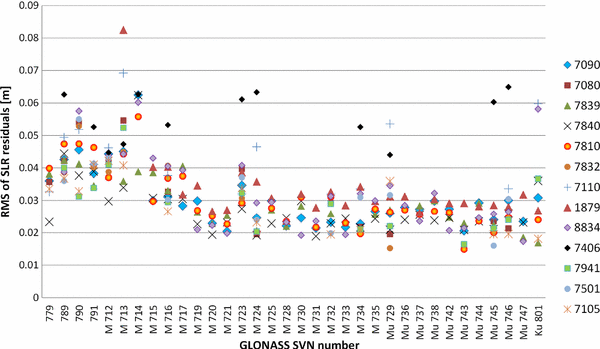
Station-dependent RMS of SLR residuals to GLONASS satellites for best performing SLR stations

References
Altamimi Z, Collilieux X, Métivier L (2011) ITRF2008: an improved solution of the international terrestrial reference frame. J Geod 85(8):457–473. doi:10.1007/s00190-011-0444-4
Appleby G, Otsubo T, Sinclair AT (1999) Comparison of precise SLR orbits of the GLONASS satellites with microwave orbits. In: Proceedings of IGEX-98 workshop, pp 247–257
Appleby G (1996) Satellite laser ranging and the Etalon geodetic satellite. Ph.D. Thesis, The University of Aston in Birmingham, UK
Appleby G (2013) Modern SLR Systems—impact from multi-constellation tracking. Herstmonceux example. GGOS—RAS/ROSCOSMOS Meeting, TUV, Austria
Arnold D, Dach R, Beutler G, Schaer S, Meindl M, Lutz S, Sośnica K, Jäggi A (2014) Impact of GNSS orbit modelling on reference frame parameters. IAG Commission 1 symposium 2014: reference frames for applications in geosciences REFAG2014, Luxembourg. http://www.bernese.unibe.ch/publist/2014/pres/DA_LUX
Arnold D, Meindl M, Beutler G, Schaer S, Dach R, Lutz S, Prange L, Sośnica K, Mervart L, Jäggi A (2015) CODE’s new empirical orbit model for the international GNSS service. J Geod (submitted manuscript)
Beard RL (2014) The NAVSTAR 35 and 36 laser retro-reflector experiments. In: Proceedings from the 19th international workshop on laser ranging, Annapolis, US, October 27–31, 2014
Beutler G, Brockmann E, Gurtner W, Hugentobler U, Mervart L, Rothacher M, Verdun A (1994) Extended orbit modeling techniques at the CODE processing center of the international GPS service for geodynamics (IGS): theory and initial results. Manuscr Geod 19:367–384
Dach R, Hugentobler U, Meindl M, Fridez P (eds) (2007) The Bernese GPS software version 5.0. Astronomical Institute, University of Bern
Dow J, Neilan R, Rizos C (2009) The international GNSS service in a changing landscape of global navigation satellite systems. J Geod 83(3–4):191–198. doi:10.1007/s00190-008-0300-3
Flohrer C (2008) Mutual validation of satellite-geodetic techniques and its impact on GNSS orbit modeling. Geodätisch-geophysikalische Arbeiten in der Schweiz, vol 75. ISBN: 978-3-908440-19-2
Fritsche M, Sośnica K, Rodriguez-Solano C, Steigenberger P, Dietrich R, Dach R, Wang K, Hugentobler U, Rothacher M (2014) Homogeneous reprocessing of GPS, GLONASS and SLR observations. J Geod 88(7):625–642. doi:10.1007/s00190-014-0710-3
Gurtner W, Noomen R, Pearlman M (2005) The international laser ranging service: current status and future developments. Adv Space Res 36:327–332. doi:10.1016/j.asr.2004.12.012
Gurtner W, Pop E, Utzinger J (2009) The new 100-Hz laser system in zimmerwald: concept, installation, and first experiences. In: Proceedings of the 16th international workshop on laser ranging, October 12–17, 2008, Poznań, pp 350–357
Jäggi A, Bock H, Meyer U, Beutler G, van den IJssel J (2015) GOCE: assessment of GPS-only gravity field determination. J Geod 89(1):33–48. doi:10.1007/s00190-014-0759-z
Lutz S, Steigenberger P, Meindl M, Beutler G, Sośnica K, Schaer S, Dach R, Arnold D, Thaller D, Jäggi A (2015) Impact of the arclength on GNSS analysis results. J Geod (submitted manuscript)
Meindl M, Beutler G, Thaller D, Dach R, Jäggi A (2013) Geocenter coordinates estimated from GNSS data as viewed by perturbation theory. Adv Space Res 51(7):1047–1064. doi:10.1016/j.asr.2012.10.026
Montenbruck O, Steigenberger P, Hugentobler U (2015) Enhanced solar radiation pressure modeling for Galileo satellites. J Geod 89(3):283–297. doi:10.1007/s00190-014-0774-0
Otsubo T, Amagai J, Kunimori H (1999) The center-of-mass correction of the geodetic satellite AJISAI for single-photon laser ranging. IEEE Trans Geosci Remote Sens 37(4):2011–2018. doi:10.1109/36.774712
Otsubo T, Appleby G, Gibbs P (2001) Glonass laser ranging accuracy with satellite signature effect. SGEO 22(5–6):509–516. doi:10.1023/A:1015676419548
Otsubo T, Appleby GM (2003) System-dependent center-of-mass correction for spherical geodetic satellites. J Geophys Res 109(B4):9.1–9.10. doi:10.1029/2002JB002209
Otsubo T, Sherwood R, Appleby G, Neubert R (2015) Center-of-mass corrections for sub-cm-precision laser-ranging targets: Starlette, Stella and LARES. J Geod. doi:10.1007/s00190-014-0776-y
Pavlis EC (1995) Comparison of GPS S/C orbits determined from GPS and SLR tracking data. Adv Space Res 16(12):55–58. doi:10.1016/0273-1177(95)98780-R
Pearlman MR, Degnan JJ, Bosworth JM (2002) The international laser ranging service. Adv Space Res 30(2):135–143. doi:10.1016/S0273-1177(02)00277-6
Petit G, Luzum B (eds) (2011) IERS conventions 2010. IERS Technical Note 36. Frankfurt am Main. Verlag des Bundesamts für Kartographie und Geodäsie, 2010
Ploner M, Jäggi A, Prohaska M, Schildknecht T, Utzinger J (2012) SLR tracking of GNSS constellations at Zimmerwald. In: Proceedings of ILRS technical workshop on laser ranging, Frascati, Italy, November 05–09, 2012
Rodriguez-Solano CJ, Hugentobler U, Steigenberger P, Lutz S (2012) Impact of earth radiation pressure on GPS position estimates. J Geod 86(5):309–317. doi:10.1007/s00190-011-0517-4
Rodriguez J, Appleby G (2013) Expanding the SLR space segment with the Galileo constellation? In: Proceedings of 18th ILRS workshop on laser ranging, Fujiyoshida, Japan
Schillak S (2013) The results of two-color observations. In: Proceedings of the 18th international workshop on laser ranging, Fujiyoshida, Japan, November 11–15, 2013
Sośnica K, Thaller D, Dach R, Jäggi A, Beutler G (2013) Impact of atmospheric pressure loading on SLR-derived parameters and on the consistency between GNSS and SLR results. J Geod 87(8):751–769. doi:10.1007/s00190-013-0644-1
Springer TA, Beutler G, Rothacher M (1999) A new solar radiation pressure model for GPS satellites. GPS Solut 3(2):50–62
Springer T, Dilssner F, Escobar D, Otten M, Romero I, Dow J (2009) Multi-technique reprocessing and combination using “space-ties”. American Geophysical Union, Fall Meeting 2009, abstract G13A-03. http://acc.igs.org/repro1/multitechnique-repro_agu09
Steigenberger P, Montenbruck O, Hugentobler U (2015) GIOVE-B solar radiation pressure modeling for precise orbit determination. Adv Space Res 55(5):1422–1431. doi:10.1016/j.asr.2014.12.009
Svehla D, Haagmans R, Floberghagen R, Cacciapuoti L, Sierk B, Kirchner G, Rodriguez J, Wilkinson M, Appleby G, Ziebart M, Hugentobler U, Rothacher M (2013) Geometrical SLR approach for reference frame determination—the first SLR double-difference baseline. IAG Scientific Assembly—150 years of IAG, 1–6 September 2013, Potsdam
Thaller D, Dach R, Seitz M, Beutler G, Mareyen M, Richter B (2011) Combination of GNSS and SLR observations using satellite co-locations. J Geod 85(5):257–272. doi:10.1007/s00190-010-0433-z
Thaller D, Sośnica K, Dach R, Jäggi A, Mareyen M, Richter B, Beutler G (2012a) GNSS satellites as co-locations for a combined GNSS and SLR analysis. Mitteilungen des Bundesamtes für Kartographie und Geodäsie Band 48. In: Proceedings of the 17th international workshop on laser ranging, vol 48, pp 82–86. ISSN 1436–3445. ISBN: 978-3-89888-999-5
Thaller D, Sośnica K, Dach R, Jäggi A, Baumann C (2012b) SLR residuals to GPS/GLONASS and combined GNSS-SLR analysis. In: Proceedings of 12th ILRS technical workshop on laser ranging, Frascati, Italy, November 05–09, 2012. http://www.bernese.unibe.ch/publist/2012/pres/dt_ILRS2012_GNSS
Thaller D, Sośnica K, Dach R, Jäggi A, P Steigenberger (2012c) GNSS orbit validation using SLR observations at CODE. In: IGS workshop 2012, Olsztyn, Poland, July 23–27, 2012
Thaller D, Sośnica K, Dach R, Jäggi A, Beutler G, Mareyen M, Richter B (2014) Geocenter coordinates from GNSS and combined GNSS-SLR solutions using satellite co-locations. In: Earth on the edge: science for a sustainable planet, international association of geodesy symposia, vol 139, pp 129–134. doi:10.1007/978-3-642-37222-3_16
Thomas L, Merkovitz S (2014) Update on the GPS III laser retroreflector array. In: Proceedings of the 19th international workshop on laser ranging, Annapolis, US, October 27–31, 2014
Urschl C, Beutler G, Gurtner W, Hugentobler U, Schaer S (2007) Contribution of SLR tracking data to GNSS orbit determination. Adv Space Res 39(10):1515–1523. doi:10.1016/j.asr.2007.01.038
Vasiliev VP, Sadovnikov MA, Shargorodskiy VD, Sokolov AL (2014) New ideas in retroreflector arrays development. In: Proceedings of the 19th international workshop on laser ranging, Annapolis, US, October 27–31, 2014
Wilkinson M, Appleby G (2011) In-orbit assessment of laser retro-reflector efficiency onboard high orbiting satellites. Adv Space Res 48(3):578. doi:10.1016/j.asr.2011.04.008
Wilkinson M (2012) SGF tracking of GNSS. In: Proceedings of the international technical laser workshop 2012 (ITLW-12), Frascati (Rome), Italy, November 5–9, 2012
Zhu SY, Reigber C, Kang Z (1997) Apropos laser tracking to GPS satellites. J Geod 71(7):423–431. doi:10.1007/s001900050110
Acknowledgments
The ILRS and IGS are acknowledged for providing SLR and GNSS data. The SLR and GNSS stations are acknowledged for a continuous tracking of the geodetic satellites and for providing high-quality SLR and GNSS observations. This work was partly supported by the Swiss National Science Foundation (SNSF) Grant No. 200020_157062 “Swiss Optical Ground Station and Geodynamics Observatory Zimmerwald”.
Author information
Authors and Affiliations
Corresponding author
Rights and permissions
Open Access This article is distributed under the terms of the Creative Commons Attribution 4.0 International License (http://creativecommons.org/licenses/by/4.0/), which permits unrestricted use, distribution, and reproduction in any medium, provided you give appropriate credit to the original author(s) and the source, provide a link to the Creative Commons license, and indicate if changes were made.
About this article

Cite this article
Sośnica, K., Thaller, D., Dach, R. et al. Satellite laser ranging to GPS and GLONASS. J Geod 89, 725–743 (2015). https://doi.org/10.1007/s00190-015-0810-8
Received:
Accepted:
Published:
Issue Date:
DOI: https://doi.org/10.1007/s00190-015-0810-8