
Abstract
The main objective of this paper is three-fold. First, to provide an overview of the current status of the power electronics technology, one of the key actors in the upcoming smart grid paradigm enabling maximum power throughputs and near-instantaneous control of voltages and currents in all links of the power system chain. Second, to provide a bridge between the power systems and the power electronic communities, in terms of their differing appreciation of how these devices perform when connected to the power grid. Third, to discuss on the role that the power electronics technology will play in supporting the aims and objectives of future decarbonized power systems. This paper merges the equipment, control techniques and methods used in flexible alternating current transmission systems (FACTS) and high voltage direct transmission (HVDC) equipment to enable a single, coherent approach to address a specific power system problem, using ‘best of breed’ solutions bearing in mind technical, economic and environmental issues.
1 Introduction
It would be fair to say that many of the ideas upon which the foundations of the Flexible Alternating Current Transmission Systems (FACTS) rest, evolved over a period of several decades, building on the experience gained in the areas of High Voltage Direct Transmission (HVDC) and reactive power compensation equipment, methods and operational control. Nonetheless, FACTS, as an integrated philosophy, was a concept brought to fruition at EPRI in the 1980’s [1, 2]. Since that time, many great breakthroughs have taken place in the area of power electronics encompassing new valves, control methods and converter topologies [3, 4]. The new developments have been incorporated into the fields of FACTS and HVDC, giving rise to a new generation of power transmission equipment in either AC or DC form, with unrivalled operational flexibility [5].
In the words of the developers of the FACTS initiative, FACTS was not intended to be a direct competitor to HVDC transmission but, rather, an initiative able to provide technical solutions to specific AC power transmission problems at a lower cost, particularly when the AC transmission corridor already existed [1].
Over the past two decades, several publications have appeared which have separately reviewed the state-of-the-art of FACTS [6, 7] and VSC-HVDC [8, 9], mainly from the vantage of high-voltage power transmission. Nevertheless, no attempt seems to have been made to provide a holistic review, as it is done in this paper, on the application of power electronics converters in the generation, transmission and distribution systems.
It ought to be said that the original boundaries between HVDC and FACTS were drawn along the types of solid-state converters employed and their control [4], but these boundaries have become blurred. On the one hand, as time has moved on, new power electronic devices such as the Voltage Source Converter (VSC), are being used in both FACTS and HVDC transmission [10]. For instance, VSCs are used in STATCOM applications, which is a FACTS technology, to provide reactive power support [11]. But, when two such devices are connected in cascade, we have the VSC-HVDC rather different from the classical HVDC transmission using thyristor-based bridges and phase control [12]. On the other hand, a wide range of enabling technologies involving power devices (power electronics, photovoltaic and wind energy systems, battery energy storage systems, electrical vehicles, etc.) and also electronic technologies (advanced protection, control, information and communication systems) have become cost effective [13] and even more powerful and popular than a decade ago [14, 15]. As a matter of fact, the introduction of these technologies in an all-encompassed manner within the electrical business provides a solid foundation on which to build the new and smarter energy grid [16]. Within this new paradigm, power electronic technology is a key component because of its ubiquitous nature in all the stages of the power system from generation to distribution and involving applications related to DC and AC systems [17].
For these reasons, according to the current state of the technology, it is proposed to remove the former boundaries originally drawn along FACTS and HVDC to focus on their basic and common underlying power electronic technology. For doing so, it is convenient to adopt a bottom-up approach, starting with the power electronics switches and following with the definition of some basic building blocks, which will be used in specific devices intended for different functionalities. As a consequence, the focus is on the power electronic device irrespective of being either a FACTS or HVDC technology – the aim being to enable the best of breed solutions underpinning the new power-carrying structures that the Smart Grid demands [18, 19].
Therefore, and according to this approach, the structure of the paper can be summarized as follows. First, power electronics components are described from scratch beginning with the most widely used power switches and the building blocks that can be formed with them. Second, a review of the power electronic devices, classified according to the way they are connected to the power system, is outlined. Third, the most important applications of these devices to power generation, transmission and distribution are described. Finally, the paper closes with the main challenges of the technology and the main conclusions of the work.
2 Power electronics elemental building blocks
The aim of this section is to introduce, following a bottom-up perspective, the basic “bricks” which are used by the various power electronic based devices addressed in the sequel of the paper.
2.1 Power electronic switches
A switch is a component that can be open and/or closed through a control signal. Power electronic switches can be broadly classified into two major groups, depending on their controllability (see Fig. 1):

Basic power electronic switches
-
1)
Line commutated switches can be turned on when the anode-cathode voltage is positive and an adequate firing signal is sent to the gate. However, once the conduction state is established they can only be turned off when the current is almost zero and the anode-cathode voltage is negative. Therefore, these devices are characterized by a single degree of freedom, namely, the firing angle, α (measured from the voltage zero-crossing). The thyristor (or SCR) is the most relevant switch within this group [20].
-
2)
Self-commutated switches can be turned on, by applying a suitable control signal to the gate, when the collector-emitter voltage is positive, and then turned off just by removing the control signal. This brings an additional degree of freedom compared to line commutated switches. The GTO, IGBT and IGCT are the most relevant switches within this category [20].
2.2 Basic building blocks
From the basic power switches outlined above, the following building blocks can be defined:
-
1)
AC-switch controllable impedance. Either a capacitor or a reactor is associated in series with an AC switch (see Fig. 2), typically comprising two antiparallel thyristors. In the simplest switched-impedance ON/OFF control scheme, the firing angle is set to α = π/2, leading to a perfectly sinusoidal current, as shown in Fig. 2a for a capacitor. In the inductor case, the amplitude of the current can be optionally regulated by suitable adjustment of the firing angle, α, leading to a non-sinusoidal current, as shown in Fig. 2b. This is referred to as a controlled impedance. In terms of α, the fundamental frequency current and associated variable susceptance are given by [10]:
$$\left\{ \begin{aligned} &\bar{I}_{TCR} = - {\text{j}}B_{TCR} (\alpha )\bar{V} \\ &B_{TCR} (\alpha ) = \frac{1}{2\pi f} \cdot \frac{2(\pi - \alpha ) + \sin 2\alpha }{L\pi } \\ \end{aligned} \right.$$(1)where α may lie in the range π/2 < α<π, L is the rated inductance value, \(\bar{I}_{TCR}\) is the current phasor, \(\bar{V}\) is the applied voltage phasor and f is the nominal frequency.
Fig. 2 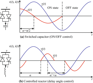
Control of switched capacitor and controlled reactor
-
2)
AC/DC Current Source Converter (CSC). The building block shown in Fig. 3, using thyristors, has long been used to inject active power from a three-phase AC system into a DC one (rectifier operation) or vice versa (inverter operation), in a controllable manner, using delay angle control. Note that the DC side in this bridge acts as an almost constant DC current source, owing to the presence of a large smoothing reactor. This device presents only one degree of freedom (the firing angle), which is used to control the transmitted active power.
Fig. 3 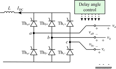
AC/DC current source converter (CSC) based on thyristors
Note that this bridge always absorbs reactive power, which is dependent on its operating point. In addition, low-order harmonics appear in the AC current in accordance to the lower switching frequency. Thus, passive filters are required to mitigate the harmonic distortion and to supply, at least a part, of the reactive power requirements.
-
3)
AC/DC Voltage Source Converter (VSC). This represents an alternative way of moving active power from a three-phase AC system to a DC one and vice versa. In this case (see Fig. 4a) the capacitors make the DC side of the converter to behave as a voltage source. The power switches are IGBTs with antiparallel free-wheeling diodes, allowing the flow of bidirectional currents. The switches are driven by PWM-based control signals, with switching frequencies in the kHz range, which are chosen to be odd integer multiples of the fundamental frequency [1, 3]. The most relevant feature of the PWM control, as illustrated in Fig. 4b, lies in the fact that it synthetizes a fundamental frequency voltage on the AC side from the DC bus, with controllable amplitude and phase, as given by the basic relationship [20]:
$$\bar{V}_{AC} = k_{l} m_{a} e^{j\varphi } V_{DC}$$(2)where \(\bar{V}_{AC}\) is the RMS fundamental-frequency component of the VSC’s output line-to-line voltage, φ is the phase angle of the complex voltage \(\bar{V}_{AC}\) relative to the system phase reference, V DC is the DC bus voltage and m a is the inverter’s amplitude modulation index. In the linear range of modulation, m a takes values in the interval: \(0 < m_{a} < 1.\) Hence, two degrees of freedom, namely active and reactive power, are available with this building block.
Fig. 4 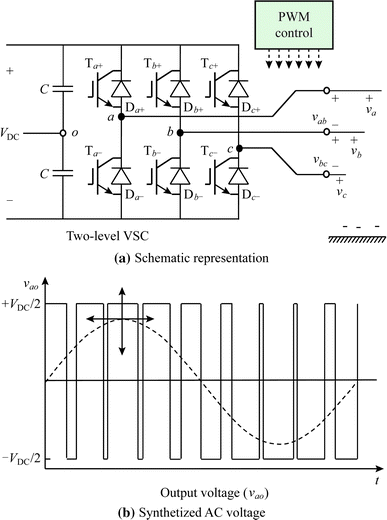
AC/DC VSC based on IGBTs


In this process, the PWM-operated VSC generates high-order harmonics, which appear as side-bands around the switching frequency and its multiples [3, 20]. The selection of the switching frequency is a trade-off between the switching losses and the filtering requirements. For this reason, in case of high power applications multilevel topologies are a possible alternative to the basic two-level VSC. Multilevel VSC operation is characterized by both low losses (reduced switching frequency) and low harmonic distortion (owing to the use of multiple DC levels). A modular multilevel VSC, as shown in Fig. 5a, stands out from other multilevel topologies because of its ability to easily accommodating any number of levels. This topology stacks simple power units containing two IGBT-valves and a small DC capacitor. In this case, the output voltage is synthetized as shown in Fig. 5b.

AC/DC modular multilevel VSC based on IGBTs
This multi-level converter technology is offered by at least one vendor, it is termed SVC PLUS®. It provides a nearly ideal sinusoidal-shaped waveform on the AC side. Therefore, there is only little –if any– need for high-frequency filtering and no need for low order harmonic filtering. SVC PLUS® uses standard components, such as typical AC power transformers, reactors, capacitors, and industrial class IGBTs that are widely used for traction and industrial drives.
3 Device configurations
The different configurations of power electronics devices, based on the above power electronic building blocks, can be classified according to its connection to the power grid. Shunt, series, shunt-series and cascade connections are reviewed in the following subsections.
3.1 Shunt connection
-
1)
Static Var Compensator (SVC). The SVC appeared in the power systems scene at least one decade before the FACTS initiative was put forward [20,21,22]. The SVC is connected in shunt with the AC system through a step-up transformer. The main function of a SVC is to supply/absorb reactive power to support a specified voltage magnitude at the high-voltage side of its connecting transformer. The one-line representation of the SVC is shown schematically in Fig. 6.
Fig. 6 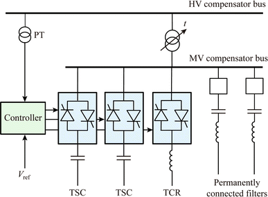
SVC schematic representation

It comprises a bank of Thyristor Controlled Reactors (TCR) in parallel with a bank of Thyristor Switched Capacitors (TSC). The TCR consumes variable reactive power up to its design limit according to (1). The TCR, however, generates harmonic currents due to the phase control [3]. For this reason, the TCR is normally connected in delta to prevent the triple harmonics from reaching the power system. In addition, passive filtering is required to mitigate the 6 k ± 1 and 12 k ± 1 generated by the six-pulse and twelve-pulse topologies respectively. The TSC generates reactive power in a variable, discrete manner, with the thyristor pairs operating as switches (ON/OFF); hence, during steady-state operation no harmonic distortion is produced by the TSC.
-
2)
Static Compensator (STATCOM). This is the modern counterpart of the SVC. Just like the SVC, its main function is to supply/absorb reactive power to support a specified voltage magnitude at the high-voltage side of its connecting transformer. Fig. 7 shows the one-line schematic circuit of the STATCOM, made up of the VSC, the smoothing inductor, the interfacing transformer and the PWM control system. As shown in the previous section, the VSC is built as a two-level or a multi-level converter [3].
Fig. 7 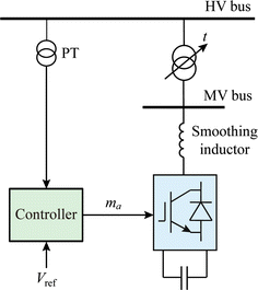
STATCOM schematic representation

The operational behaviour of the STATCOM is superior to that of the SVC. Being based on a VSC, the STATCOM may be seen as a variable and controlled voltage source, as opposed to a variable shunt susceptance [10]. Basically, it behaves like a fast synchronous condenser without moving parts [1, 5]. Therefore the STATCOM does not use bulky inductors and banks of capacitors to absorb and to generate reactive power, respectively [1, 3]. The generation/absorption process is carried out by the action of the VSC voltage control according to (2) to yield either leading or lagging VAR operation to satisfy operational requirements [1]. Note that the current injected by the STATCOM has to be orthogonal to the bus voltage considering a lossless approach because no active power exchange is allowed due to the isolated DC bus of the VSC. The smoothing inductor is used between the VSC and the step-up transformer to eliminate the high-order harmonics. The DC capacitor is used to support and stabilize the DC voltage [1].
An equipment manufacturer has recently patented a new VAR compensation equipment selecting the best attributes of the SVC and the STATCOM [23].
3.2 Series connection
-
1)
Thyristor Switched Series Compensator (TSSC). The TSSC connects in tandem a series of paralleled capacitor-thyristor modules in order to modify the apparent electrical length of the line, as shown schematically in Fig. 8 for one phase. A block capacitor becomes active by turning off its associated thyristor valve and inactive otherwise, i.e., when the thyristor valve is on the capacitor is bypassed. Therefore, no harmonic distortion is generated. This arrangement enables controllable series compensation, up to the rated capacity, in a discrete, stepwise manner. The larger the number of active modules, the higher the degree of series capacitive compensation.
Fig. 8 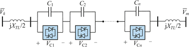
TSSC schematic representation
-
2)
Thyristor Controlled Series Compensator (TCSC). The TCSC performs a similar function to the TSSC but its control is carried out in a continuous manner. In addition to increasing the stability margin of the system, the TCSC has shown to damp Synchronous Series Resonance (SSR) and power oscillations [1]. Like the TSSC, it uses a series of blocks connected in tandem but each block comprises the parallel combination of a capacitor and a TCR, as shown schematically in Fig. 9.
Fig. 9 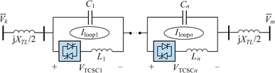
TCSC schematic representation


Basically, the TCSC would exhibit the behaviour of a variable series reactance governed by the TCR’s firing angle α. Therefore, it should be possible to adjust the reactance of the line to perform an effective regulation of the power flow through the series compensated transmission line. Depending on the firing angle, the TCSC may operate in capacitive or inductive modes. However, there is little incentive for inductive operation since this would increase the electrical length of the transmission line, with adverse consequences on stability margins, and extra losses [3]. Note that in this case the TCR harmonic currents do not tend to escape towards the network; instead, the harmonics are trapped inside the TCSC because of the low impedance of the capacitor compared to the network equivalent impedance [10]. TCSCs have been installed in countries that have long transmission distances, such as the USA, Brazil, China and India. It seems that there is limited scope for using this technology in Europe, with the Nordic countries being the exception. Indeed, Fingrid Oyj, the Finish TSO, has shown recent interest in upgrading some of their series compensated transmission lines to include the dynamic characteristics afforded by the TCSC.
-
3)
Synchronous Series Static Compensator (SSSC). The SSSC is the counterpart of the STATCOM for series devices. As shown in Fig. 10, it is composed of a VSC connected through a series coupling transformer. The SSSC injects a series voltage to the incoming nodal voltage to control the power flow through the power line. However, much like the STATCOM, the series voltage must remain in quadrature with the line current for the DC bus voltage to remain constant and no active power being exchanged (assuming a theoretical lossless condition). Note that the SSSC is a fractional power device that has to be rated to the line current but the rated voltage is only a fraction of the rated line voltage. Therefore, with a small rating, it may have a high impact on the controllability of the power flow, which is one of its main advantages [1].
Fig. 10 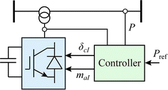
SSSC schematic representation
-
4)
Solid State Tap Changer (SSTC). This device uses a set of power electronic-based switches, usually made up of two antiparallel thyristors which replace the mechanical switches used in the regulation windings of conventional power transformers, as shown in Fig. 11. The thyristors are operated in an ON/OFF mode, so that no harmonic distortion is generated. Depending on the selected switch, the transformer turns ratio gets modified, with ensuing adjustments to the secondary voltage, to meet operational needs.
Fig. 11 
Solid state tap changer (SSTC) schematic representation


3.3 Shunt-series connection
-
1)
Solid State Voltage Regulators. This is the electronic version of conventional voltage regulators, and an alternative to the SSTC analysed in the previous subsection. The device controls the nodal voltage by introducing a series voltage using a series transformer as shown in Fig. 12a. This series voltage is obtained from a shunt exciting transformer which, in addition to a number of thyristor-based AC/AC bridges, conforms a controllable voltage source. The thyristor switches are operated using an ON/OFF control and therefore no harmonic distortion is introduced. Note that depending on the winding arrangement of the exciting transformer, two types of regulators are obtained. On the one hand, a Solid State Tap Changer (SSTC) is obtained if the transformer has wye-wye windings because it is possible to change the magnitude of the controlled node as shown in Fig. 12b. On the other hand, if a wye-delta arrangement is used in the exciting transformer then a Solid State Phase Shifter (SSPS) is generated. In this case, as shown in Fig. 12c, an orthogonal voltage is introduced leading mainly to a change in the phase, and to a lesser extent, the magnitude of the controlled node. Therefore, this device can be used to control in a discrete manner the power flow between the nodes the series transformer is connected to. Neither SSTC nor SSPS seem to have been used so far in any practical installation, but only conventional versions based on mechanically driven servomotors.
Fig. 12 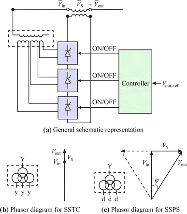
Solid state voltage regulator
-
2)
Unified Power Flow Controller (UPFC). This is a compound equipment with two VSCs connected in shunt and series, respectively, and sharing a common DC bus. This device, whose schematic diagram is shown in Fig. 13, has a great operational functionality combining the control capabilities of the STATCOM and the SSSC.
Fig. 13 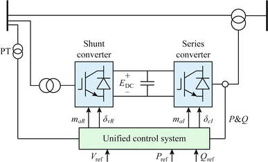
UPFC schematic representation
It is capable of regulating, simultaneously, the voltage magnitude at the high-voltage node of the shunt connected VSC, the active power flow arriving at the receiving node of the series connected transformer (opposite node to that where the shunt converter is connected) along with the injection of reactive power at that node. Regulation of these parameters is limited by the ratings of the shunt and series converters. Despite its operational flexibility and great expectations when it was first conceptualized, the UPFC has not been so far a commercial success. Only two prototypes are known to exist in the world [1, 24] until recently where the world’s first 220 kV UPFC based on MMC VSCs has been installed in Nanjing (China) [25].


3.4 Cascade connections
-
1)
LCC-HVDC. DC power transmission using two or more of the six-pulse thyristor bridges shown in Fig. 3, suitably connected, is termed classical HVDC transmission. The most basic configuration involves two converters with their DC terminals directly connecting with each other, to form a monopolar, back-to-back HVDC link. One converter station acts as a rectifier and the other acts as an inverter. In high-voltage, high-power applications the converters are twelve-pulse as opposed to six-pulse and are housed in the same building. On the other hand, if the purpose is to transmit power over a long distance then the two converter stations are linked by a DC transmission line or a submarine DC cable depending on the geography separating the two converter stations, which may currently span several thousands of kilometers. These schemes are termed point-to-point HVDC links. In general, HVDC links may be either monopolar or bipolar. Cases of a monopolar, back-to-back and a bipolar, point-to-point HVDC schemes are exemplified, in schematic form, in Fig. 14a and b, respectively.
Fig. 14 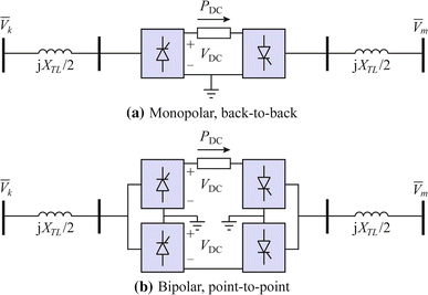
HVDC systems
The bipolar link is composed of two mono-polar links, one at positive and one at negative polarity with respect to ground. In fact, each monopolar side can operate on its own with ground return but with the two poles having equal currents then they cancel each other’s ground return to zero. Indeed, the ground path is a valuable resource but limited to emergency period, when one pole is out of service.
The use of phase-controlled thyristors as shown in a previous section is characterized by reactive power consumption and low order harmonics. Therefore, in this type of applications passive filtering on the AC and DC sides is required as well as local reactive power compensation to achieve a suitable operation of the link.
Notice that the current flow is from the rectifier towards the inverter and so is the power flow when the voltage polarity is positive. Alternatively, the power follows an opposite direction to the current when the voltage polarity reverses, an operational characteristic achieved through firing angle control.

Several LCC-HVDCs are in operation around the world [26, 27]. However, the technology has intrinsic limitations when applied to multi-terminal HVDC systems because LCC-HVDC is based on current balances. Hence, only serial, multi-terminal HVDC schemes seem to be realisable using this technology.
-
2)
VSC-HVDC. The control functionality of the mono-polar, back-to-back VSC-HVDC link is comparable to that of the UPFC but at the expense of using two full rated converters, as illustrated in Fig. 15. Nevertheless, its overall functionality is far greater than the UPFC because asynchronous interconnection between AC systems with different frequencies is enabled [3].
Fig. 15 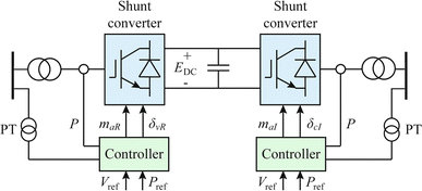
Mono-polar, back-to-back VSC-HVDC
Moreover, the two VSCs do not need to be connected back-to-back but, instead, linked by a cable to transport electrical power with less power loss than an AC transmission line of comparable rating and distance. Such an arrangement is known as mono-polar, point-to-point VSC-HVDC link. However, bipolar schemes are favored over the basic mono-polar link, on grounds of higher power throughputs and reliability [4].
Recent developments of the VSC-HVDC technology are in the arena of the so-called Multi-Terminal VSC-HVDC systems [16, 28,29,30]. The basic representation of the back-to-back VSC-HVDC link shown in Fig. 15 may be expanded to exemplify the case when three VSCs are interconnected on their DC sides through DC cables to make up a three-terminal VSC-HVDC system, as shown schematically in Fig. 16. This is a generic concept that may comprise n VSCs to link n AC systems of varying sizes, topologies and operational complexity. The DC cables may be overhead, underground or submarine, according to practical requirements. The DC network may also exhibit an arbitrary topology and it may contain DC loads, DC generation and storage systems [19]. Just as in meshed AC transmission systems, there are transmission lines with non-regulated and regulated power flows, power flows sharing between neighboring transmission lines, nodes with regulated and non-regulated voltage and so on. Finally, this DC network may even comprise a single node bus where the n VSCs would be sharing a DC capacitor, i.e. multi-terminal back-to-back configuration [31].
Fig. 16 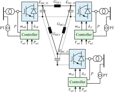
Three-terminal VSC-HVDC system
-
3)
DC/DC converters. Power transformers are used in AC systems to suitably interconnect sections of the power grid with different voltage levels. As a matter of fact, power transformers were largely responsible for the great development of the current AC systems, instead of the primitive DC-based ones. However, nowadays the power system has to integrate more and more DC subsystems and components, connected to a diversity of voltage levels, from LV to UHV. This creates a clear need for efficiently performing voltage level conversion at the points of interconnection. DC/DC converters are power electronic devices intended for this application. However, the kind of converters traditionally used for low power applications [32], cannot be directly applied when high powers and high voltages have to be handled. Basically, the most widely adopted solution consists of using DC/AC conversion, with or without transformer, based on two-level or multilevel VSCs, as shown in Fig. 17 [33, 34]. Note that the frequency on the AC side can be much higher than the power frequencies (i.e., 50 or 60 Hz), in order to reduce the transformer size and, hence, that of the DC/DC converter.
Fig. 17 
DC/DC converter based on VSCs


4 Applications
4.1 Generation/storage interfacing
In the last two decades, increasingly more powerful IGBT-based power converters have found a major application niche as suitable interfaces between the grid and the usually asynchronous and intermittent renewable sources [35,36,37].
This fruitful relationship started with the incorporation of STATCOMs into older generations of wind farms based on fixed-speed induction machines. The aim was to dynamically provide reactive power support so that those wind generators could satisfy the more stringent low-voltage ride through capability imposed by new grid codes.
Then, more efficient and mechanically more robust variable-speed turbines emerged, namely the doubly-fed induction machine (DFIM) type, in which the rotor current is controlled by a fractional converter, or permanent magnet synchronous machine (PMSM) type, whose stator is fed through a full size converter (Fig. 18).

Wind power interfaces
Regarding photovoltaic (PV) power plants, they usually connect to the grid through a DC/DC boost converter and an inverter, as shown in Fig. 19. Old generations of converters, most of them still in use today, were simply able to track the maximum power of the PV modules, while keeping unit power factor at the point of connection. However, the new generation based on VSCs can and are required to perform more sophisticated functions, such as voltage regulation and contribution to frequency stability.

PV and storage interface
The VSC also combines very well with most types of energy storage systems, including redox flow and lithium-ion batteries [1]. Today’s battery energy storage systems (BESS) can reliably and efficiently undergo charging/discharging cycles through a similar interface to that of PV systems (Fig. 19). Provided there is sufficient energy stored in the battery pack, the BEES associated controllers can quickly react by injecting active power into the AC system to provide frequency support in the event of synchronous generators frequency oscillations, as well as reactive power for voltage regulation [1]. Moreover, they can work as grid-forming devices in charge of voltage and frequency control of autonomous grids. Indeed, not only can a modern BESS emulate the operation of a synchronous generator (in the absence of rotating parts) but also provide additional flexibility, such as adaptive time-varying behavior during faults or perturbations [38]. It is very likely that, once BESS prices decrease further, this equipment will become ubiquitous in the power grid since it has a potential major role to play in electrical energy retailing.

Frequency deviation at the Nordic system under a 12% loss of conventional generation
As renewable power displaces more and more conventional generation, electricity grids are losing inertia and synchronizing power, which is detrimental for system stability. Consequently, the industry is currently involved in the development of more sophisticated controllers for renewable generators and storage systems, allowing them to contribute to short-term frequency support by providing synthetic inertia. This possibility is analyzed in [39] for the Nordic European system, where a huge number of DFIM-based wind farms can be retrofitted with this kind of controllers. Fig. 20 shows how the presence of synthetic inertia reduces the initial frequency drop (at the cost of wind generators kinetic energy) while, at the same time, delays its recovery to the steady-state value.
4.2 Transmission
Power electronics-based components fulfill several controllability functions in high-voltage transmission, with a varying degree of effectiveness, as exemplified in the generic transmission system shown in Fig. 21.

Transmission system to illustrate the applications of various flexible transmission system components
Perhaps the two most commonly known are power flow control and voltage regulation/reactive power injection control; notice that these two functions are mutually exclusive when performed by a shunt controller. Shunt VAR compensation is most effective when applied at a point of the system (e.g., node C) that more closely resembles, electrically speaking, the midpoint of the transmission system.
-
1)
Reactive power and voltage regulation. The use of shunt compensation is pervasive in high-voltage AC power transmission; it is difficult to think of a transmission system that nowadays will not have one or more compensators installed. Several of the power electronics-based equipment listed in Section 3, enable either voltage regulation or controlled injection of reactive power at its point of connection with the AC power grid, namely, SVC and STATCOM. In spite of the performance of both devices being almost the same at rated voltage, it has to be remarked that huge differences appear in case of reduced voltages. This is because the SVC behaves as a controllable susceptance, leading to a low current in case of low voltages, while the STATCOM responds like a voltage source, which may control the injected current almost independently of the network voltage. Therefore, from the operational perspective, one of the main criticisms levelled at the SVC when compared to the STATCOM refers to its impaired ability to contribute reactive power in the presence of low system voltages – for instance, in cases of voltage collapse. Furthermore, any of the compound devices that use one or more VSCs, such as UPFC or BESS, would also have such a capability.
-
2)
Transient and dynamic stability. All the power electronics-based compensators listed in Section 3 have the capability to impact positively on power system stability, with a varying degree of success, depending on which system parameters they influence most and their speed of response [40]. As stated in the section above, the SVC and STATCOM will perform similarly when operating at around their design ratings. This criterion can be extended to cover the dynamic range of operation. To show the effectiveness of the STATCOM, located midpoint as in Fig. 21, to improve the dynamic stability, its voltage response to a load change in the same node is given in Fig. 22. The effectiveness of the STATCOM is self-evident from this sample result. Note that with a fast controllable injection of reactive power it is possible to control the nodal voltage rejecting the perturbation created by the load increase.
Fig. 22 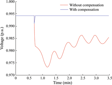
Dynamic stability improvement: comparison of voltage evolution in a transmission line with and without shunt compensation at midpoint during a transient due to a load increase

In addition, controllable-shunt compensators, like STATCOM and SVC, may contribute to the transient stability of the system. For this purpose, a short circuit fault in the line between the circuit breakers CB1 and CB2 is analyzed with and without compensation as shown in Fig. 23. Note that without compensation, depending on the fault clearing time of the circuit breakers, the system may become unstable due to the acceleration of the generators, as can be seen in the evolution of the rotor angle. The reason is that, without compensation, there is a larger unbalance between the slowly varying mechanical power driving the generators and the instantaneously changing electrical power, which gets drastically reduced in proportion to the voltage reduction at node C, until the short circuit is cleared. On the contrary, in the presence of controllable shunt compensation, the stability is enhanced owing to the fast reactive power injection that keeps the voltage at node C as high as possible.

Transient stability improvement: comparison of voltage evolution in a transmission line with and without shunt compensation at midpoint during a short-circuit
-
3)
Loop flow control. In principle, electrical power flows in meshed transmission systems follow physical laws’ principles as opposed to network ownership, contractual obligations or thermal limits. The difference between the physical flow or free-flow path and the contract path is termed, in the parlance of power engineers, “loop flow”. More often than not, a “loop flow” yields a degree of circulating power that leaves available capacity underutilized [1]. From the engineering vantage, this is not desirable and a range of suitable solutions have been put forward to reign on the “loop flows” and make the physical power flows to better conform to the contract paths or to ensure that no system equipment becomes overloaded on a long-term basis, compromising its integrity. The available solutions to contend with this undesirable phenomenon require the installation of new equipment considering that a trade-off between investment and operational functionality ought to be considered carefully. Conventional solutions range from the installation of new generating plants at the appropriate locations, the building of new transmission lines or the introduction of the electromechanical phase-shifting transformer. This latter component is able to alter the phase angle difference, and thus controlling the power flow, but with the problems related to any electromechanical component [41]. Alternatively, several of the power electronic-based equipment described in Section 3, have the capability to perform the same function more effectively. These devices can be classified as follows: those that alter the series line reactance (TSSC and TCSC), those that alter the phase angle (SSPS) and those that alter both parameters (SSSC and UPFC). To illustrate the free flow of power let us refer to the generic transmission system of Fig. 21. It is assumed, for the purpose of this discussion, that Area 1 and Area 2 export power to Area 3 through the mesh of AC and DC transmission lines shown in the figure. It is further assumed that the power flows follow the transmission paths A-B, B-C, A-C and that the installation of the phase shifter SSPS in line A-C becomes necessary in order to limit the power flow through this transmission line, below its rated power capacity, which would otherwise become exceeded. It is clear that transmission lines A-B and B-C would have spare rating capacity to carry the ensuing re-directed power flows. On the other hand, the parallel AC/DC transmission path linking nodes C and D provides a fair degree of dynamic power regulation, using the fast power controllability afforded by the point-to-point HVDC link and the AC transmission line with variable series impedance control.
4.3 Distribution
The main applications of the flexible power components in distribution networks can be explained using Fig. 24.

Distribution system for illustrating the applications of flexible power components
-
1)
Load compensation. The individual loads connected to distribution systems are far from being ideal components drawing balanced sinusoidal currents. They are characterized by having poor power factor, being unbalanced and introducing waveform distortion in the distribution system, degrading power quality [42, 43]. In this respect, utilities have strict grid connection codes to limit the perturbations that certain loads may introduce into the system [44,45,46], and maintain high power quality standards [47]. The shunt-connected AC/DC VSC with isolated DC bus is the conventional solution that can be effectively used to compensate this type of disturbances, as shown in Fig. 24. If the device is intended for power factor and unbalance compensation, it is usually termed D-STATCOM [48, 49]. When the goal is to compensate harmonics, it is referred to as an active power filter (APF) [50, 51]. The principle of operation of both devices is based on the injection of a set of compensation currents, which turn the total current perfectly balanced and sinusoidal. However, this is not a straightforward task because the unbalance and harmonic components of the load current need to be computed in real-time. That is the reason why accurate reference current computation methods are key to achieve an effective compensation [52]. Hence, it is important to use alternative calculation algorithms to the classical ones (the instantaneous pq theory [51] or conventional dq. [53]) which do not rely on the assumption of sinusoidal conditions of the supply voltage [54], since this condition is not fulfilled in distribution system with high penetration of distorted loads.
-
2)
Dynamic voltage support. During the last decades, a steadily transformation of the load equipment has occurred. Classical electromechanical components are being replaced by electronic ones, providing higher functionalities and improved efficiency but also with a higher sensitiveness to the voltage power quality [55]. Voltage disturbances like voltage sags may have a catastrophic effect on industrial processes [56,57,58], causing production shutdowns leading to non-negligible economic costs [42]. Voltage sags experienced by a sensitive load connected to a distribution system are mainly produced by short-circuit faults [59] in adjacent feeders to the one where the load is connected to, as shown in Fig. 24. However, it has to be considered that faults cannot be fully eliminated in spite of the utilities’ many efforts to prevent them by adequate tree trimming, insulation washing, adding animal guards, installation of line arresters, etc. Therefore, it is mandatory for those sensitive final users with critical processes to be protected against this type of disturbances. For this purpose, series compensation is quite effective as shown in Fig. 24. In this case, the series-connected AC/DC VSC has to inject a series voltage to restore the voltage prior to the fault. Different alternative topologies involving DC energy storage or additional shunt converters have been reported [60]. The dynamic compensation using these devices is challenging because of two main issues. First, the immunization degree strongly depends on the type of voltage sag but also on the selected topology and the implemented control algorithm [60]. Therefore, the selection of a cost-effective immunization technique is difficult. Second, the detection technique for voltage sags requires advanced real-time algorithms able to quickly detect voltage phase-angle jumps and the different voltage sequences [61].
-
3)
Flexible meshed operation of radial networks. Distribution systems are radially operated in spite of being structurally meshed, as shown in Fig. 24, because of the simplicity of their operation and protection. However, with the advent of distributed generation (DG) this traditional layout has to be reconsidered. As a matter of fact, massive penetration of DG may generate problems to this radially operated system ranging from congestions to overvoltages. A possible solution to overcome this problem is to replace the normally open switches located in the traditional switching centers, used for assuring a back-up supply in case of failure, with power electronic based DC links composed of a number of AC/DC VSCs sharing a common DC bus [62], as shown in Fig. 24. This device provides new supply points among adjacent feeders where the active and reactive power flows can be controlled adding flexibility to the system operation. On the one hand, the new active power transfer capability between the feeders may release congestions. On the other hand, taking into account that the switching centers are usually located at the remote end of the feeders, the reactive power injection may contribute effectively to the voltage regulation. The flexible DC links can be operated considering different purposes: maximize DG penetration, maximize network loadability and minimize power losses [63]. Alternative shunt-series topologies to the conventional multi-terminal AC/DC VSC, have been also proposed aimed at reducing the investment cost of the device [64]. However, it has to be mentioned that even in the case of the conventional back-to-back VSC, the investment is profitable when used for the massive integration of renewable energies [65]. Finally, it is worth mentioning that the flexible DC link includes a DC bus that can be used for integrating generation (PV) or loads such as electric vehicle recharging stations. Therefore, this device can be envisioned as a first step towards the future hybrid AC/DC distribution grids.
5 Future trends and major challenges
Taking into account the current state of the art of power electronic applications to power systems, it is possible to briefly outline the potential avenues of research in the near future.
Regarding the generation side, a continuous growth of wind and PV systems is expected, that will increase to unprecedented levels the amount of non-synchronous generation connected to the grid through power converters. On the one hand, new converter topologies featuring higher efficiencies will be developed [66]. On the other hand, the higher share of renewables in the generation mix will call for advanced controllers mimicking or even improving the behavior of conventional power plants [67]. Moreover, a massive penetration of distributed and renewable resources will involve a considerable effort in terms of new standards, addressing communication and protection issues, as well as grid codes imposing stringent connection requirements [68].
Regarding transmission applications, future prospects will be mainly determined by the increased capability of VSC-HVDC to handle higher voltage and power levels. Recent developments show that this technology is currently limited to 1.8 GW and ±500 kV [69, 70]. However, conventional HVDC installations based on thyristors are rated up to 8 GW and ±800 kV [71, 72 ]. Other technological issue requiring more attention in the next years is the development of simpler and more effective HVDC circuit breakers [73, 74]. DC faults are usually cleared by AC switches in case of point-to-point HVDC. However, this protection scheme cannot be longer applied in case of multi-terminal HVDC because the stability of the interconnected AC systems may be jeopardized. In addition, regarding also the interactions of AC and DC systems, some basic research will be needed on how to massively integrate overlying HVDC lines, spanning very long distances, without collapsing the underlying AC grids [75].
In case of distribution systems, a vast improvement of power quality phenomena is envisioned owing to the generalized use of power electronic devices [76, 77]. The massive penetration of new agents with power electronic components (electric vehicle or distributed generation) will lead to a huge number of distributed energy resources which can be controlled in a coordinated manner to optimize the operation of the utilities [78]. It can be surmised here that power distribution systems which currently are three-phase radial AC systems would migrate to become multi-terminal, bipolar, VSC-DC systems [79,80,81]. This would be so because of reasons of higher energy throughputs, lower energy losses and smaller footprints of the DC equipment and cables. On the DC side of the system, the conventional three-phase loads may be served in a more controllable manner while enabling the direct connection of DC DERs, such as PV battery packs, fuel cell stacks, PV stacks and EV re-charging stations. Furthermore, if the amount of energy produced by the in situ generation and storage is sufficient to meet the local demand plus the associated power losses, then the DC feeders may act as an independent micro-grid, isolated from the HV utility supply, with the AC connection points taking the character of back up supply points [82]. During this transition, an interesting issue worth researching, particularly in urban areas, is how to use the current AC infrastructures to host DC ones in order to reduce the cost as much as possible [83].
6 Conclusion
This paper has reviewed the power electronic technology used nowadays in generation, transmission and distribution levels of the power system. From a historical perspective, this equipment has been usually grouped within FACTS or HVDC technologies. These power electronic-based devices serve the purpose of controlling one or more electrical parameters of the power grid in an almost instantaneous basis, adding unrivalled operational flexibility while remaining a cost effective technical solution. Therefore, the barrier between FACTS and HVDC may no longer be of application nowadays, when AC and DC systems coexist along the entire power system. For this reason, a bottom-up approach has been proposed embracing both technologies, from the most basic power electronic valves to the final application. Moreover, in the upcoming smart grid paradigm, where power electronics will be a key component, it is necessary to fill the gap between power systems and power electronics engineers. The latter ones have to clearly understand the possibilities and limitations of this technology while the former have to be aware about the possible applications. The new challenges faced in a decarbonized future will involve the massive deployment of both AC and DC electronically-controlled components, for which a coordinated and more dynamic interplay between power electronics and power system communities is required. Taking this in mind, this paper would like to contribute to give a holistic approach of the state of the technology.
References
Hingorani NG, Gyugyi L (2000) Understanding FACTS: concepts and technology of flexible AC transmission systems. Wiley-IEEE, New York
Song YH, Johns AT (1999) Flexible AC transmission systems (FACTS). The Institution of Electrical Engineers (IEE), London
Acha E, Agelidis VG, Anaya-Lara O et al (2001) Power electronic control in electrical systems, Newnes Power Eng Ser 106–152
Arrillaga J, Liu YH, Watson NR (2007) Flexible power transmission: the HVDC option. Wiley, Chichester
Sood VK (2004) HVDC and FACTS controllers: applications of static converters in power systems. Kluwer Academic Publishers, Boston
Mathur RM, Varma RK (2002) Thyristor-based FACTS controllers for electrical transmission systems. IEEE, Piscataway
Eslami M, Shareef H, Mohamed A et al (2012) A survey on flexible AC transmission systems (FACTS). Przegald Elektrotechniczny (Electr Rev) 88(1A):1–11
Flourentzou N, Agelidis VG, Demetriades GD (2009) VSC-based HVDC power transmission systems: an overview. IEEE Trans Power Electron 24(3):592–602
Liu YH, Zhang RH, Arrillaga J et al (2005) An overview of self-commutating converters and their application in transmission and distribution. In: Proceedings of the 2005 IEEE/PES Asia and Pacific transmission and distribution conference and exhibition, Dalian, China, 15–18 Aug 2005, p 7
Acha E, Fuerte-Esquivel CR, Ambriz-Perez H et al (2004) FACTS: modelling and simulation in power networks. Wiley, Chichester
Zhang XP, Rehtanz C, Bikash P (2012) Flexible AC transmission systems: modelling and control. Springer, Berlin
Arrillaga J (1998) High voltage direct current transmission. The Institution of Electrical Engineers (IEE), London
Acha E (2013) Modelling distributed energy resources in energy service networks. The Institution of Electrical Engineers (IEE), London
Borlase S (2012) Smart grid: infrastructure, technology and solutions. CRC Press, Boca Raton
Momoh JA (2012) Smart grid: fundamentals of design and analysis. Wiley-IEEE, Hoboken
Gellings CW (2009) The smart grid: enabling energy efficiency and demand response. CRC Press, Boca Raton
Wang P, Goel L, Liu X et al (2013) Harmonizing AC and DC: a hybrid AC/DC future grid solution. IEEE Power Energy Mag 11(3):76–83
Ekanayake J, Jenkins N, Liyanage L et al (2012) Smart grid: technology and applications. Wiley, Chichester
Acha E, Castro LM (2016) A generalized frame of reference for the incorporation of multi-terminal VSC-HVDC systems in power flow solutions. Electr Power Syst Res 136:415–424
Mohan N, Undeland TM, Robbins WP (1995) Power electronics: converters, applications and design. Wiley, New York
Hingorani N (1993) Flexible AC transmission. IEEE Spectr 3:40–45
Miller TJE (1982) Reactive power control in electric systems. Wiley, New York
Torhonen O (2016) Benefits of main reactor-based SVC in utility applications. Master Thesis. Tampere University of Technology, Tampere, Finland
Han YS, Suh IY, Kim JM et al (2005) Commissioning and testing of the KangJin UPFC in Korea. In: Proceedings of the 2004 CIGRE, Paris, France, 24 August 2004, B4-211
Li P, Lin JJ, Kong XP et al (2016) Application of MMC-UPFC and its performance analysis in Nanjing Western Grid. In: 2016 IEEE PES Asia-Pacific power and energy engineering conference (APPEEC), Xi’an, China, 25–28 October 2016
Litzenberger W, Lips P (2007) Pacific HVDC intertie. IEEE Power Energy Mag 5(2):45–51
Hammons TJ, Lescale VF, Uecker K et al (2012) State of the art in ultrahigh-voltage transmission. Proc IEEE 100(2):360–390
Van Hertem D, Ghandhari M (2010) Multi-terminal VSC HVDC for the European supergrid: obstacles. Renew Sust Energy Rev 14(9):3156–3163
Li XL, Yuan ZC, Fu J et al (2014) Nanao multi-terminal VSC-HVDC project for integrating large-scale wind generation. In: 2014 IEEE PES general meeting| conference & exposition, National Harbor, MD, USA, 27–31 July 2014
Tang GF, He ZY, Pang H (2014) R&D and application of voltage sourced converter based high voltage direct current engineering technology in China. J Mod Power Syst Clean Energy 2(1):1–15. doi:10.1007/s40565-014-0045-3
Reynolds MA (2012) Tres Amigas superstation—large scale application of VSC back-to-back technology. In: IEEE PES Trans. & Dist., Orlando, FL, USA, 7–10 May 2012
Tofoli FL, de Castro Pereira D, de Paula WJ et al (2015) Survey on non-isolated high-voltage step-up dc–dc topologies based on the boost converter. IET Power Electron 8(10):2044–2057
Lachichi A (2013) DC/DC converters for high power application: a survey. In: Proceedings of the 3rd international conference on electric power and energy conversion systems, Istanbul, Turkey, 2–4 October, 2013, 4 pp
Yang J, He ZY, Pang H et al (2015) The hybrid-cascaded DC–DC converters suitable for HVDC applications. IEEE Trans Power Electron 30(10):5358–5363
Carrasco JM, Franquelo LG, Bialasiewicz JT et al (2006) Power-electronic systems for the grid integration of renewable energy sources: a survey. IEEE Trans Ind Electron 53(4):1002–1016
Blaabjerg F, Yang YH, Ma K (2013) Power electronics-key technology for renewable energy systems-status and future. In: Proceedings of the 3rd international conference on electric power and energy conversion systems, Istanbul, Turkey, 2–4 October, 2013, 6 pp
Teodorescu R, Liserre M, Rodriguez P (2011) Grid converters for photovoltaic and wind power systems. Wiley, Chichester
Remon D, Cantarellas AM, Rakhshani E et al (2014) An active power self-synchronizing controller for grid-connected converters emulating inertia. In: Proceedings of the 2014 international conference on renewable energy research and application (ICRERA’14), Milwaukee, WI, USA, 19–22 October 2014, 424–429 pp
Seyedi M, Bollen M (2013) The utilization of synthetic inertia from wind farms and its impact on existing speed governors and system performance. Vindforsk Project Report V-369, Part 2. ELFORSK, Stockholm, Sweden
Anderson PM, Fouad AA (2003) Power system control and stability. IEEE, Hoboken
Van Hertem D, Rimez J, Belmans R (2013) Power flow controlling devices as a smart and independent grid investment for flexible grid operations: Belgian case study. IEEE Trans Smart Grid 4(3):1656–1664
Caramia P, Carpinelli G, Verde P (2009) Power quality indices in liberalized markets. Wiley, Chichester
Baggini A (2008) Handbook of power quality. Wiley, Chichester
IEC/TR 61000-3-6: 2008 Electromagnetic compatibility (EMC)—Part 3–6: limits—assessment of emission limits for the connection of distorting installations to MV, HV and EHV power systems
IEC/TR 61000-3-14: 2011 Electromagnetic compatibility (EMC)—part 3-14: assessment of emission limits for harmonics, interharmonics, voltage fluctuations and unbalance for the connection of disturbing installations to LV power systems
IEEE Std 519—2014 IEEE recommended practices and requirements for harmonic control in electrical power systems. 2014
EN 50160 Voltage characteristics of electricity supplied by public electricity networks
Ghosh A, Ledwich G (2002) Power quality enhancement using custom power devices. Kluwer Academic Publishers, Boston
Escobar G, Stankovic AM, Mattavelli P (2004) An adaptive controller in stationary reference frame for D-STATCOM in unbalanced operation. IEEE Trans Ind Electron 51(2):401–409
Akagi H (2005) Active harmonic filters. Proc IEEE 93(12):2128–2141
Akagi H, Watanabe EH, Aredes M (2007) Shunt active filters. Instantaneous power theory and applications to power conditioning. Wiley, Hoboken, pp 109–220
Maza-Ortega JM, Perales-Esteve M, Burgos-Payan M et al (2005) Reference current computation methods for active power filters: accuracy assessment in the frequency domain. IEEE Trans Power Electron 20(2):446–456
Bhattacharya S, Divan DM, Banarjee BB (1993) Control reduction of terminal voltage harmonic distortion (THD) in a hybrid series active parallel passive filter system. In: Proceedings of the 24th annual IEEE power electronics specialist conference (PESC’93), Seattle, WA, USA, 20–24 June 1993, 779–786 pp
Maza-Ortega JM, Rosendo-Macias JA, Gomez-Exposito A et al (2010) Reference current computation for active power filters by running DFT techniques. IEEE Trans Power Deliv 25(3):1986–1995
Dugan RC, Wayne Beaty H, McGranaghan MF (1996) Electrical power systems quality. McGraw-Hill, New York
Pedra J, Corcoles F, Sainz L (2007) Effects of unsymmetrical voltage sags on squirrel-cage induction motors. IET Gen Transm Distrib 1(5):769–775
Pedra J, Sainz L, Corcoles F et al (2005) Symmetrical and unsymmetrical voltage sag effects on three-phase transformers. IEEE Trans Power Deliv 20(2):1683–1691
Pedra J, Corcoles F, Suelves FJ (2005) Effects of balanced and unbalanced voltage sags on VSI-fed adjustable-speed drives. IEEE Trans Power Deliv 20(1):224–233
Bollen MHJ (2000) Understanding power quality problems. IEEE, New York
Nielsen JG, Blaabjerg F (2005) A detailed comparison of system topologies for dynamic voltage restorers. IEEE Trans Ind Appl 41(5):1272–1280
Fitzer C, Barnes M, Green P (2004) Voltage sag detection technique for a dynamic voltage restorer. IEEE Trans Ind Appl 40(1):203–212
Okada N, Takasaki M, Sakai H et al (2007) Development of a 6.6kV-1 MVA transformerless loop balance controller. In: Proceedings of the 2007 IEEE power electronics specialists conference (PESC’07), Orlando, FL, USA, 17–21 June 2007, 1087–1091 pp
Romero-Ramos E, Gomez-Exposito A, Marano-Marcolini A et al (2011) Assessing the loadability of active distribution networks in the presence of DC controllable links. IET Gen Transm Distrib 5(11):1105–1113
Maza-Ortega JM, Gomez-Exposito A, Barragan-Villarejo M et al (2012) Voltage source converter-based topologies to further integrate renewable energy sources in distribution systems. IET Renew Power Gen 6(6):435–445
Gomez-Exposito A, Maza-Ortega JM, Romero-Ramos E et al (2013) Enhancing the integration of renewables in radial distribution networks through smart links. In: Iniewski K (ed) Smart grid infrastructure & networking. McGraw-Hill, New York, pp 155–179
Blaabjerg F, Ma K, Yang YH (2014) Power electronics—the key technology for renewable energy systems. In: Proceedings of the 9th international conference on ecological vehicles and renewable energies (EVER’14), Monte-Carlo, Monaco, 25–27 March 2014, 11 pp
Zhang WY, Remon D, Rodriguez P (2017) Frequency support characteristics of grid-interactive power converters based on the synchronous power controller. IET Renew Power Gen 11(4):470–479
Mohseni M, Islam SM (2012) Review of international grid codes for wind power integration: diversity, technology and a case for global standard. Renew Sust Energy Rev 16(6):3876–3890
Lundberg P, Gustafsson A, Jeroense M (2015) Recent advancements in HVDC systems: HVDC and power electronics technology and development. In: Proceedings of the 2015 CIGRE, Paris, France, 31 August 2015
Sellick RL, Akerberg M (2012) Comparison of HVDC light (VSC) and HVDC classis (LCC) site aspects, for a 500 MW 400 kV HVDC transmission scheme. In: Proceedings of the 10th IET international conference on AC/DC power transmission (ACDC’12), Birmingham, UK, 4–5 December 2012, 6 pp
Oni OE, Davidson IE, Mbangula KNI (2016) A review of LCC-HVDC and VSC-HVDC technologies and applications. In: Proceedings of the IEEE 16th international conference on environment and electrical engineering (EEEIC’16), Florence, Italy, 7–10 June 2016, 7 pp
Lin WX, Jovcic D, Yao LZ et al (2015) Investigation of interconnecting two Chinese LCC-HVDC through LCL DC/DC converter. In: Proceedings of the 2015 IEEE PES Asia-Pacific power and energy engineering conference (APPEEC’15), Brisbane, Australia, 15–18 November 2015, 5 pp
Gupta R, Barker CD, Adamczyk A et al (2016) Protection coordination in multi-terminal HVDC networks for DC fault clearance. In: Proceedings of the 13th international conference on development in power system protection (DPSP’16), Edinburgh, UK, 7–10 March 2016, 6 pp
Li YL, Shi XJ, Wang F et al (2016) DC fault protection of multi-terminal VSC-HVDC system with hybrid dc circuit breaker. In: Proceedings of the 2016 IEEE energy conversion congress and exposition (ECCE’16), Milwaukee, WI, USA, 18–22 September 2016, 8 pp
Fairley P (2016) Why Southern China broke up its power grid. IEEE Spectr 53(12):13–14
Domijan A, Montenegro A, Keri AJF et al (2005) Simulation study of the world’s first distributed premium power quality park. IEEE Trans Power Deliv 20(2):1483–1492
Delfanti M, Quaia S (2012) Analysis and comparison of premium power park performances. Electr Power Syst Res 83(1):176–184
Barragán-Villarejo M, Marano A, García-López FP et al (2015) Coordinated control of distributed energy resources and flexible links in active distribution networks. In: Proceedings of the 4th international conference on renewable power generation (RPG’15), Beijing, China, 17–18 October 2015, 6 pp
Kaipia T, Salonen P, Lassila J et al (2006) Possibilities of the low voltage DC distribution systems. In: Proceedings of the 2006 Nordic distribution automation conference (NORDAC’06), Stockholm, Sweden, August 2006, 10 pp
Emhemed AAS, Burt GM (2014) An advanced protection scheme for enabling an LVDC last mile distribution network. IEEE Trans Smart Grid 5(5):2602–2609
Liu X, Wang P, Loh PC (2011) A hybrid AC/DC micro-grid and its coordination control. IEEE Trans Smart Grid 2(2):278–286
Justo JJ, Mwasilu F, Lee J et al (2013) AC-microgrids versus DC-microgrids with distributed energy resources: a review. Renew Sust Energy Rev 24:387–405
Antoniou D, Tzimas A, Rowland SM (2015) Transition from alternating current to direct current low voltage distribution networks. IET Gen Transm Distrib 9(12):1391–1401
Acknowledgements
This work was supported by Spanish Ministry of Economy and Competitiveness and Junta de Andalucía through the projects ENE2014-54115-R and TEP-7411.
Author information
Authors and Affiliations
Corresponding author
Additional information
CrossCheck date: 14 June 2017
Rights and permissions
Open Access This article is distributed under the terms of the Creative Commons Attribution 4.0 International License (http://creativecommons.org/licenses/by/4.0/), which permits unrestricted use, distribution, and reproduction in any medium, provided you give appropriate credit to the original author(s) and the source, provide a link to the Creative Commons license, and indicate if changes were made.
About this article

Cite this article
MAZA-ORTEGA, J.M., ACHA, E., GARCÍA, S. et al. Overview of power electronics technology and applications in power generation transmission and distribution. J. Mod. Power Syst. Clean Energy 5, 499–514 (2017). https://doi.org/10.1007/s40565-017-0308-x
Received:
Accepted:
Published:
Issue Date:
DOI: https://doi.org/10.1007/s40565-017-0308-x