
Abstract
The incidence of soil slope instability is, and has been, a natural hazard of major proportions and is ongoing to this day. While stabilization can be afforded by excavation and reconstruction, oftentimes structures and utilities are involved requiring in situ stabilization methods. This paper is focused accordingly. The method uses soil nails or soil anchors connected to a geosynthetic surface covering which is tensioned thereby stabilizing the encapsulated soil and providing tensile reinforcement. The paper is subdivided as follows: (i) introduction and theoretical background, (ii) required theoretical modifications, (iii) basics of soil nailing and anchors along with surface geosynthetics effects, (iv) implementation of the technique, (v) current activities by manufacturers, suppliers and ground modification companies, and (vi) summary and conclusions.
Introduction and Theoretical Background
Of the various types of ground failure hazards, landslides are at, or near the top, of such lists. The NRC [1] estimates 25–50 lives lost in America each year and the USGS [2] estimates the annual economic loss at $2–5 B. Worldwide, the situation is likely to be much greater as regular news events attest. The typical agents leading to landslides are gravity, seismic, explosives, mass effects and many different sources of water, Terzaghi [3]. The above said, the typical soil slopes being addressed herein can be considered as “shallow and/or localized slope instabilities”. They are extremely common and generally of great interest certainly to the parties directly involved, see Fig. 1 for examples in this regard.

Shallow and/or localized soil slope failures to be addressed in this paper. a Typical shallow soil slope landslide (from Wikipedia). b Possible complex sliding surfaces ref. Keller [4]
Indeed, there are many geotechnical engineering methods available to analyze such slopes wherein the trajectory of the potential failure plane is of major importance. If it is rotational (circular) a simplified Bishop method (SBM) is commonly used and if it is translational (polygonal) the U.S. Army Corps of Engineers (COE) wedge method is commonly used. The SBM is expressed as follows, Bishop [5] and Lambe and Whitman [6]. Note that the factor-of-safety (FS) is not an explicit expression and thus the equation must be solved iteratively requiring the use of a computer code, of which there are many.
where FS is the factor-of-safety of the slope, ϕ is the friction angle of soil, c is the cohesion of soil, li is the length of ith slice, μi is the pore water pressure at ith slice, θi is the orientation of ith slice, and Wi is the weight of ith slice.
The COE method consists of utilizing force polygons of active, passive and sometime neutral block wedges, and searching for equilibrium of the soil masses within the potential failure planes. Numerically, the situation can be configured into the quadratic equation as follows which can be easily adapted using a spread sheet analysis, Koerner and Soong [7].
where
FS is the factor-of-safety of the slope, WA is the weight of active wedge, Wp is the weight of passive wedge, β is the slope angle with horizontal, NA W sin β, ϕ is the friction angle of soil, and c is the cohesion of soil.
Both of these two numerical methods will be reconfigured in light of stabilization methodology to be developed in this paper.
Required Theoretical Modifications
A key feature of this particular stabilization method is to use a ground surface geosynthetic material so as to modify the encapsulated in situ soil’s shear strength via compaction and/or consolidation. Of course, dry or partially saturated soils will compact if appropriately stressed, and saturated or nearly saturated soils will consolidate with both situations leading to increased friction (ϕ) and/or cohesion (c) values. The ϕ and c values (using either total or effective stresses) in the previous equations will thereby increase leading to commensurate increases in the FS-value of the slope.
Soil Nailing and Surface Geosynthetic Effects
The concept of this in situ stabilization method is shown in Fig. 2 wherein the original focus was on soil nails and the surface geosynthetic. Each item will be described separately along with the more recent ground anchors and the subsequent system that is created. Numeric examples using both the SBM and COE methods insofar as increasing FS-values will also be given.

Concept of nailed geosynthetic covering system, Koerner [8]. a General configuration of complete system. b Free-body diagram of netting. c Free-body diagram of anchor. d Free-body diagram of contained soil
Soil Nailing
Soil nailing was developed in the 1970s by many contractors in North America and Europe to provide temporary support systems for construction of underground excavations, FHWA [9]. Using steel nails of 12–25 mm diameter, they are driven into the soil beyond the potential failure plane and resist pullout by their circumferential friction. The ground surface is usually covered with reinforced shotcrete with a lock-off plate and nut embedded in the shotcrete layers along with its welded wire cage or mesh. The nails are installed by impact driving, jetting, explosives or compressed air. They can also be screwed into the soil. While the technique was developed by ground modification contractors (and included several now-elapsed patents), the theoretical basis was provided by Shen et al. [10, 11]. The technique is shown in Fig. 3a, b. Hausmann [12] extended their work so as to envision that the nails would bend as the shear plane was mobilized, thereby providing a shear force and resisting moments as shown in Fig. 3c, d. That said, the latter mechanism probably only functions for small diameter non-grouted nails as used herein.

Traditional soil nailing (mod. from Hausmann [12]). a Schematic diagram of nailed wall. b Tensile pullout behavior. c Additional stabilizing force. d Development of passive resistance
Ground Anchors
More recently introduced are low capacity ground anchors which are well suited for the type of in situ slope stabilization envisioned herein, see Fig. 4a. They consist of a collapsed anchor with a steel cable pushed or driven into the soil by a temporarily attached steel rod. At the desired depth, the steel rod is pulled out of the ground leaving the anchor and its attached cable leading to the surface. The cable is then tensioned at the ground surface thereby rotating the anchor 90° so as to have its maximum surface area bearing against the soil at the desired depth. As the cable is tensioned from the ground surface, the soil’s resistance at depth is being engaged in a gradually increasing passive earth pressure state. The limit is when the soil reaches its full passive equilibrium state. At this point the soil has entered a failure state which is not desirable. The process is nicely shown in Fig. 4b. These anchors are available in many variations (Duckbill, Platipus, Manta Ray, Batwing, Stingray, etc.) and are fully illustrated and described on the internet. They are regularly used for all types of walls and slopes (both new and remediation), as well as for stabilizing utility poles, signage, trees, etc. It should be noted that high capacity structural foundation anchors are not necessary since their anchorage resistance is far greater than can be mobilized at the ground surface by geosynthetics and their connections.

Installation of low capacity ground anchors and their behavior while being stressed (ref. Platipus-ARGS [13]). a The three steps to the installation of an anchor system. b Typical anchor behavior in field and laboratory
Surface Geosynthetic Covering
The entire ground surface must be covered with an appropriate geosynthetic or other suitable flexible material. Flexibility is critical and hard surfaces like shotcrete are not acceptable. Even further, the surface geosynthetic must be made to accommodate the nails (or anchors) which protrude through them and then suitably attached. There are many types of “lock-off” assemblies available in this regard. Once the surface geosynthetic is attached to the nails or anchors they are driven further so as to tension the geosynthetic and fully engage the encapsulated soil thereby compacting or consolidating it for strength enhancement; recall Fig. 2d in this regard. These attachment locations are the highest stressed regions of the systems as indicated in the laboratory testing of a knit geotextile shown in Fig. 5. It is important to recognize that the nails (or anchors), their surface covering attachments, and their spacing are a “system” and are most economical when they are a matched system insofar as their strength capabilities are concerned. As will be seen later, current methods use geogrids, erosion control materials, composite geosynthetics and even welded wire mesh on the soil’s surface.

Laboratory testing of specially designed knit geotextile [14]
Numeric Examples Showing System Benefits
Two numeric examples of the method follow; one for rotational failure surfaces and one for translational surfaces.
Rotational Failures Using Simplified Bishop Method (SBM)
The SBM given as Eq. 1 is adjusted and modified (see bold terms) for nailed geosynthetics as follows:
where the following are adjusted and modified terms: ϕ is the friction angle of soil, ϕm is the modified friction angle (where ϕm ≥ ϕ), c is the cohesion of soil, cm is the modified cohesion (cm ≥ c), (1+ f) is the contribution of the anchors (nails) penetrating the failure plane toward stability, (Fi cos βi) is the contribution of the stressed geosynthetic at the bottom of the slice (where equilibrium equations are taken) to stability, (Fi di /R) is the moment due to the pressure of the stressed geosynthetic at the ground surface, Fi is the force on ith slice at its base, βi is the angle of ith slide with horizontal, di is the arc length of ith slide, and R is the radius of potential failure arc.
Using this equation for the following conditions; slope angle = 55°, slope height = 7.6 m, soil unit weight = 16.8 kN/m3, ϕ = 20°, c = 9.5 kN/m2 without a nailed geosynthetic, results in FS = 0.967. The influence of the nails and stressed surface netting (three of the bold terms in Eq. 3) results in Fig. 6a, b and c where the FS-value is steadily increasing by the action of each term. The cumulative effect of all three factors is given in Fig. 6d. Note that there is no assumed increase in the shear strength parameters, ϕ and c, which would further increase the factor-of-safety.

Parametric study of factors influencing soil slope stability using nailed geosynthetics [14]. a Effect of rods (1 + f)/R term on factor of safety. b Effect of F (cos) term on factor of safety. c Effect of ∑(Fd)/R term on factor of safety. d Cumulative effect of all actions except increased ϕ and c of the encapsulated soil mass
Translational Failures Using Corps of Engineers (COE) Method
In a parallel manner as with the SBM, the COE method can be reconfigured for nailed geosynthetics by adding a tensile force (T) to account for the nails as well as an increase in shear strength parameters, ϕ and c. Equation 4 illustrates these modifications where the bold variables can be adjusted accordingly.
where
Using these equations for the following conditions without nailed geosynthetics, slope angle = 55°, slope height = 7.6 m, soil unit weight = 16.8 kN/m2, ϕ = 20°, and c = 9.5 kN/m2, results in FS = 0.95. With nailed geosynthetics and slope angle = 55°, slope height = 7.6 m, soil unit weight = 16.8 kN/m2, ϕ = 23°, c = 11 kN/m2 and T = 25 kN/m, the selection results in FS = 1.24; i.e., a 30 % increase in factory-of-safety.
Implementation of Nailed Geosynthetics
The original development of nailed geosynthetics (in this case the knit geotextile shown in Fig. 5) was implemented using the following field procedure:
-
Rough grade the slope by removing low areas preferably having a slightly mounded (upward concave) ground surface.
-
Unroll the geosynthetic from top of slope.
-
Fix the geosynthetic at top and edges using long nails or U-shaped pins.
-
Position nails down and across slope using sledge hammer.
-
Return and drive nails by impact hammer (or other), to intersect the failure plane and beyond as far as possible.
-
Fix the washer or lock-off assembly to the top of the nails.
-
Continue driving thereby stressing the geosynthetic covering into the soil and in so doing compact and/or consolidation the encapsulated soil.
-
Proceed down and across slope.
-
Vegetate the slope as desired.
-
Revisit the site for redriving nails as necessary.
Two sites were stabilized using the technique.
-
Upper Merion, Pennsylvania slope in an active failure state was successfully stabilized in 1986 and has apparently remained stable to date as shown in Fig. 7.
Fig. 7 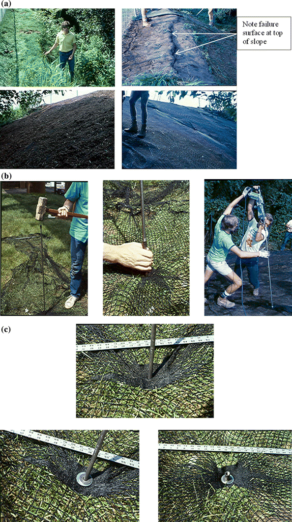
Field deployment on silty clay slope which was in an unstable state
-
Gibbsboro, New Jersey steep slope of ∼45° which was not successful since the concave grading of the soil was not possible hence the contact of the geotextile was inadequate.

Current Activity by Industry
In 1986 the author took out a patent for “Anchored Spider Netting” of precisely the type of system described thus far in this paper. Other than some collaborating research at the University of Michigan, Ghiassian et al. [15] there was absolutely no interest in the technique to the author’s knowledge. This “silence” lasted for the 17-years of the patent’s viability and even 5-years beyond. Then in ca. 2008, a plethora of similar methods emerged with clever variations until presently at least ten-organizations (manufacturers, suppliers, and contractors) have ongoing activities. The significant variations from the method described are felt to be the following:
-
Different methods of advancing soil nails.
-
Use of cabled anchors instead of soil nails.
-
Use of several different geosynthetics instead of knit geotextiles.
-
Steel wire mesh is also being used.
-
Attachment to the surface covering has been enhanced.
-
A focus on erosion control has been added.
-
Activity appears to be strong and growing.
Table 1 gives an overview of this activity and it should be noted that all of these manufacturers, suppliers and contractors have websites describing their particular approach to the method. The level of their individual success is unknown but it is sufficient to sustain interest and marketing activities.
Summary and Conclusions
The described technique of nailed (or anchored) geosynthetics for in situ stabilization of quasi-stable or even failing soil slopes has been described and illustrated in this paper. Its focus is on relatively small and localized soil slopes which can be remediated in a low-cost manner. The method itself falls into the category of “ground modification”, aka soil nails or soil anchors, with the addition of a surface geosynthetic or other flexible covering. As such, the mechanisms provided are the following:
-
Reinforcement.
-
Densification and/or consolidation.
-
Erosion control.
Paradoxically, after 22-years since the original method was developed with no activity, current activity is quite strong with at least ten manufacturers/suppliers/contractors providing a close variation of the original method.
It is important to recognize that rather than being a purely empirical method, in situ slope stabilization has a formalized and well accepted theoretical background. It has been used and modified accordingly in this paper. Other than increasing surface effects on the encapsulated soil mass’s shear strength parameters, there are positive effects afforded by soil nails and to a related extent by cabled soil anchors. These adaptations were made and illustrated by numeric examples for both the simplified Bishop method and the COE wedge method.
We hope that going forward the method will gain even further acceptance for the worthwhile application of providing low cost in situ soil slope stabilization.
References
National Research Council (1995) Estimated losses and research funding of selected ground failure hazards in the United States. National Academy Press, Washington
United States Coast and Geodetic Survey (2010) (on world wide web)
Terzaghi K (1950) Mechanisms of landslides, engineering geology (Berkley). Geological Society of America, Boulder, pp 83–123
Keller R (2000) Unpublished Memorandum on State and Local Procurement of Recycled Products, Northeast Maryland Waste Disposal Authority, February 19
Bishop AW (1955) The use of the slip circle in the stability analysis of slopes. Geotechnique 5:7–17
Lambe TW, Whitman RV (1969) Soil Mechanics. Wiley, New York
Koerner RM, Soong T-Y (2005) Analysis and design of veneer cover soils. Geosynth Int 12(1):28–49
Koerner RM (1984) In-Situ soil stabilization using anchored nets. In: Proceedings of the low cost and energy saving construction materials, Rio de Janeiro, Brazil, July, pp 465–478
Federal Highway Administration (1998), Manual for design and construction monitoring of soil nail walls FHWA-SA-96-969R, U. S. DOT, p 92
Shen CK, Bang S, Herrman LR (1981) Ground movement analysis of earth support system. J Geotech Eng Div ASCE 107(GT12):1609–1624
Shen CK et al (1981) Field measurements of an earth support system. J Geotech Eng Div ASCE 107(GT12):1625–1637
Hausmann MR (1990) Engineering principles of ground modification. McGraw-Hill Publishing Co., New York, NY, p 632
Platipus-Anchors, Platipus Earth Anchoring Systems (on world wide web) (current)
Koerner RM, Robins JC (1986) In-situ stabilization of soil slopes using nailed geosynthetics. In: Proceedings 3 ICG, Vienna, Austria, pp 395–400
Ghiassian H, Hryciw RD, Gray DN (1996) Laboratory testing apparatus for slopes stabilization by anchored geosynthetics. Geotech Test J GTJODJ ASCE 19(1):65–73
Acknowledgments
This paper is made available through financial assistance of the members, Affiliated Members and Associate Members of the Geosynthetic Institute (GSI). We sincerely thank them in this regard. See our website at www.geosynthetic-institute.org for their identification and contact persons.
Author information
Authors and Affiliations
Corresponding author
Rights and permissions
Open Access This article is licensed under a Creative Commons Attribution-NonCommercial-NoDerivatives 4.0 International License, which permits any non-commercial use, sharing, distribution and reproduction in any medium or format, as long as you give appropriate credit to the original author(s) and the source, and provide a link to the Creative Commons license. You do not have permission under this license to share adapted material derived from this article or parts of it.
The images or other third party material in this article are included in the article’s Creative Commons license, unless indicated otherwise in a credit line to the material. If material is not included in the article’s Creative Commons license and your intended use is not permitted by statutory regulation or exceeds the permitted use, you will need to obtain permission directly from the copyright holder.
To view a copy of this license, visit (http://creativecommons.org/licenses/by-nc-nd/4.0/)
About this article

Cite this article
Koerner, R.M. In-Situ Stabilization of Soil Slopes Using Nailed or Anchored Geosynthetics. Int. J. of Geosynth. and Ground Eng. 1, 2 (2015). https://doi.org/10.1007/s40891-014-0002-2
Received:
Accepted:
Published:
DOI: https://doi.org/10.1007/s40891-014-0002-2