
Abstract
This paper focuses on the construction technique of road embankment which crosses a section of about 11 km on sabkha soils of Chott El Hodna in Algeria. Due to the poor bearing capacity of sabkha surface and the rising water table over the surface, serious difficulties were encountered during the investigation of the subsurface soil and the construction of the first embankment layers. In this construction site, the use of basal geosynthetic layer to maintain the performance of embankment was found to have relevant reinforcing effect by increasing the soil bearing capacity to allow safe construction of the first layers and improving the compaction quality. Based on the in situ observations and the geotechnical investigation, numerical simulations were performed using the software PLAXIS. The results have shown the contribution conditions of geosynthetics to improve the bearing capacity of sabkha soils.
Introduction
Road engineers in Algeria like Tunisia, Saudi Arabia, USA, India and Australia often face the challenge to design a solid road foundation on top of very soft soils which are characterized by sabkha soils. These soils are coastal and inland saline deposits that are formed in arid regions. In their in situ states, the sabkha soils have high compressibility and low bearing capacity. Sabkha soils are very sensitive to moisture whereby complete collapse and large reduction in the bearing capacity are anticipated when these soils are in contact with water [1, 2]. Such behaviour is attributed to the fact that some of the cementing materials that bond the mineral grains of sabkha together, such as halite, are highly soluble in water, while others, such as gypsum, aragonite, and calcite are less soluble. The work done by Aiban et al. [2] on different sabkha soils confirms the acute water sensitivity and chemical aggressiveness of sabkhas. Several field stabilization techniques have been implemented to improve the inferior sabkha properties, with various degrees of success [2, 3]. However, it has generally been found that the use of geosynthetics as reinforcement has the advantages of being practical, economical, and easy to apply [4–7]. Geosynthetics have pervaded almost all the branches of geotechnical engineering with almost an infinite number of applications [8]. One of the most common uses of geosynthetics is in pavement construction, where soft and low-strength soil conditions prevail. In this application, the benefits associated with the use of geosynthetic reinforcement are: (a) to minimize differential and total settlements; (b) to improve the bearing capacity of the soft subsoil; (c) to prevent contamination of the base materials allowing for more open graded, free-draining aggregates; (d) to reduce the pavement thickness; and (e) to extend the service life of the pavement [4, 7, 9–24]. Some previous research and experimental studies on sabkha soils have been conducted in the last few decades. Abduljauwad et al. [4] carried out laboratory tests to investigate the contribution of geotextiles to the performance of sabkha subgrade. They concluded that the improvement in bearing capacity due to the use of geotextiles was much higher when the sabkha soils were flooded with water. Aiban and Ali [6] conducted pull-out tests on geotextiles embedded in sand and sabkha soils to study frictional characteristics of sand-geotextile-sand and sabkha-geotextile-sand interfaces and to compare the pull-out resistance of locally available nonwoven geotextiles taking into account different test parameters. Aiban et al. [2] performed an experimental work to assess the influence of nonwoven geotextiles on performance of sabkha soil from Saudi Arabia. Their results demonstrated that the use of nonwoven geotextiles improved the bearing capacity of the sabkha soil.
The objective of this paper is to present on the one hand, the advantages observed in situ by the use of geosynthetics in the construction of road embankment crossing a section of about 11 km on sabkha of Chott El Hodna in Algeria, and on the other hand, the qualitative results of numerical simulations using the software PLAXIS [25] of the effect of reinforcement on the bearing capacity improvement of sabkha soils.
Description and Geotechnical Investigation of the Site
The case study concerns the construction of the road embankment linking the two towns of Ain El Khadra and M’Cif which extend for approximately 23 km. This road crosses a section of about 11 km on the sabkha of Chott El Hodna located in the north middle part of Algeria (Fig. 1). The sabkha of Chott El Hodna is a large closed flat of 26,000 km2 developed where surface runoff converges from the Saharian Atlas in the south and the Tellien Atlas in the north and also by soil infiltration. In summer, the surface is partially dry and encrusted with salt but gets flooded in winter. The road embankment divides the sabkha in two basins. The hydrological study shows the maximum water level which may reach 1.40 m over ground surface for a thousand-year-old return period event. Figure 2 presents a photograph showing the sabkha subsurface state. The visual appearance of the sabkha site indicates that the feet sink into the soil from approximately 4–6 cm.

Location of the analysed road embankment in the sabkha of Chott El Hodna, Algeria

Subsurface state of the sabkha
According to geosynthetic field guidance and Holtz et al. [26] recommendations for estimating subgrade strengths, this sabkha soil has viscous consistency and a California Bearing Ratio (CBR) of about 1–1.5 %.
It is important to note that the soil of this sabkha is misleading from bearing capacity point of view. In a dry state, a truck and even a pneumatic compactor can circulate, whereas a low wetting of the soil reduces its bearing capacity considerably (Fig. 3). This is due to the fact that the salts form a cementing agent in the sabkha soils which increases their strength. These bonds can be lost upon wetting with water and, hence, the strength can be significantly decreased. The observation of this high sensitivity to water is in good agreement with that founded on the sabkhas of Saudi Arabia [2].

Low bearing capacity of the saturated sabkha soil without geotextile
Due to the poor bearing capacity sabkha surface and the rising water table over the ground surface, serious difficulties were encountered during the investigation of the subsurface soil. Therefore, the subsurface investigations were accomplished only after installation of the two first layers of embankment separated by geotextile and reinforced by geogrid.
The program of sabkha subsurface investigations comprised a borehole, cone penetration test and vane shear test for every 300 m of the embankment length. The sabkha soils of Chott El Hodna are highly variable in both the horizontal and vertical directions. Figure 4 shows a generalized soil profile.

Profile and typical cone penetration of sabkha soils at the site of road embankment
Subsurface conditions within the sabkha consist of a brown muddy clay layer, underlain by a grey marl layer and gypsum concretions with traces of fine sand. Below this layer, the sabkha deposit is characterized by alternating sandy clay and sandy marl layers. The laboratory testing results of undisturbed samples obtained from borehole of about 20 m depth show that the compression index C c varying from 0.30 to 0.56, the plasticity index I p varying from 27.5 to 48.5 and the dry density varying between 1.38 and 1.64 indicating high soil compressibility. The undrained shear strengths of the layers of brown muddy clay and grey marl vary from 9 to 30 kPa. In the sabkha centre, the thickness of the very soft layers may reach 10 m depth. These results are in good agreement with the static cone penetration test results showing low point resistance for this depth (Fig. 4).
Construction Technique of Road Embankment
Different methods were proposed to improve the engineering properties of sabkha soils located from the Chott El Hodna, Algeria. These include chemical stabilization using cement and lime, soil replacement, vertical drains in combination with preloading, stone columns and reinforcement using geosynthetics. The success of the improvement method depends on the type and quantity of salts and their solubility, permeability of soil, temperature and chemical characteristics of ground water. Sabkha soils of Chott El Hodna are associated with many geotechnical problems, due to the presence of digenetic salts of different sizes, shapes and compositions; and the shallow saline ground waters. Furthermore, the susceptibility of these soils to strength loss and collapse upon wetting makes their use in construction of road embankment very risky and hazardous. Because of these characteristics, the use of geosynthetics as soil improvement technique is preferred due to the relative ease and quick construction techniques, as well as for their economic advantages and the associated road improvement. The geotextile is used to separate the subsoil and the embankment aggregate. Whereas the reinforcement by geogrid layer is used to increase the stiffness of the foundation, improve the compaction quality, and carry the tension forces induced by embankment weight on the subsoil. For the embankment, a sandy gravel material was chosen to allow free drainage of the foundation soils and reducing the pore pressure build-up below the embankment. The construction steps used as shown in Fig. 5 can be summarized as the following:

Reinforcement and protection of the road embankment
-
Laying directly over sabkha surface a nonwoven separating geotextile to prevent the contamination of embankment fill, facilitate the implementation of the first layer of embankment and allow construction equipments to access to sites where the sabkha soils are too weak to support the initial construction work (Fig. 6).
Fig. 6 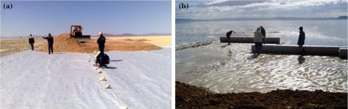
Laying directly over sabkha surface a nonwoven geotextile. a Dry state. b Flooded state
-
Construction of the first lift of 30 cm thickness with static compaction until obtaining a plane surface.
-
Laying a biaxial geogrid layer over the first lift to uplift the tensile strength to the embankment base (Fig. 7).
Fig. 7 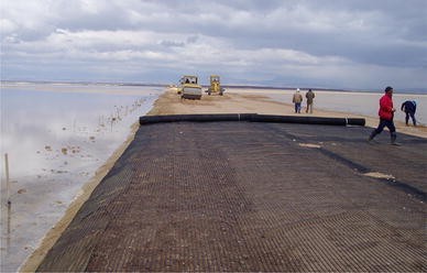
Laying the biaxial geogrid over the first lift of embankment
-
Construction of the embankment in layers with compaction control by static plate load test.
-
Installation of the reinforced HDPE hydraulic tubes of 1000 mm diameter at 20 cm above the sabkha ground surface in order to compensate the remaining consolidation settlement. These tubes particularly have the advantages: flexibility, easy installation and less sensitivity to sabkha soil aggressivity.
-
Protection of embankment slopes and tube edges against erosion with separate geotextile and riprap.
-
Laying the unbound base course and surface dressing wearing course which absorbs the deformations better than the asphalt concrete.


Figure 8 illustrates the Young’s modulus E v2 of the reloading cycle measured from the static plate test for 2nd and 4th layers of the embankment. Measurements were carried out for different distances of embankment length along the axis of embankment, as well as on the left- and right-hand sides. The results of the compaction control show that the values of E v2 are greater than 45 MPa from the second fill layer corresponding to 60 cm of the embankment height. In addition, it is observed that the improvement of the compaction quality increases with the embankment height which reflects the reduction effect of the weak subgrade. After 4 years of the opening of this road to traffic, the road inspection showed no sign of failure or degradation.

Young’s modulus E v2 of the plate reloading on the embankment layers: a 2nd fill layer and b 4th fill layer
Numerical Modelling
A series of two-dimensional finite element analyses on a reinforced and unreinforced (with and without geosynthetics) embankment over soft ground were performed in order to assess the effect of reinforcement on the bearing capacity of the sabkha subgrade after the construction of the two first lifts of embankment (Fig. 9). The soft ground is an 8 m thick sabkha soil. The average wheel width and the centre-to-centre distance between pairs of the vehicle wheels were taken to be 0.6 and 2 m, respectively. The analysis was performed using the finite element program PLAXIS software package [25]. This software is popular among the geotechnical engineering practitioners.

Geometry of geosynthetic reinforced two first lifts of embankment on soft foundation soil
Due to symmetry, only half the embankment was modelled. The size of the modelled domain was determined on the basis of trial calculations, during which the mesh was progressively refined and its boundaries extended until stresses and deformations at the highly-stressed zones have sufficiently stabilized. Results from the trial calculation showed that the modelled area had an overall horizontal width of 27 m and a vertical thickness of 8.6 m. At the left and the right boundaries the horizontal displacement was fixed but vertical displacement was allowed. At the bottom boundary both the horizontal and vertical displacements were fixed. Plane strain condition and 15-node triangular elements were used for analysis. PLAXIS provides an automated mesh generation system, in which the model is discretized into standard elements. The finite element mesh of geometry is presented in Fig. 10.

Finite element mesh of the geometry
A variety of soil models are built in the computer code chosen for this study. However the linear elastic-perfectly plastic Mohr–Coulomb criteria is used to model the embankment fill and the soft soil for its simplicity, practical importance and the availability of the parameters needed. This model requires five parameters: Young’s modulus (E), Poisson’s ratio (υ), friction angle (φ), cohesion (C), and dilatancy angle (ψ). The soil parameters obtained from laboratory tests used in this numerical analysis are depicted in Table 1.
The geosynthetic (geotextile and geogrid) was represented using a 5-node tension element in PLAXIS. The only material property required for the geosynthetic is the tensile stiffness “EA” which is used in this analysis as 580 kN/m for the geogrid and 50 kN/m for geotextile. These values were chosen in accordance with the manufacturer’s manual of the products.
The interaction between the geosynthetic and soil was modelled at both sides by means of interface elements. The material properties of the interface are related to the adjacent soil material, except that a strength reduction factor (R inter) is used to represent the roughness of the interface elements [25]. The Mohr–Coulomb model is used to describe the behaviour of interfaces. The R inter value for the soil-geosynthetic interface used in this analysis is 2/3, which is recommended by the manufacturer of the products and based on the experimental results conducted by Aiban and Ali [6].
In the present case study, serious difficulties were encountered during the investigation of the subsurface soil and embankment construction. Deep ruts and local failures were developed on the subgrade and on the trafficked fill layers. To overcome the site difficulties, the geosynthetic membrane effect was investigated. To simulate this effect, large displacement finite element analysis was carried out to quantify the improvement of bearing capacity achieved due to the geosynthetic reinforcement.
The analysis was carried out according to the construction sequence of the embankment in the field. Three steps were followed in this simulation. In the first step the initial effective stresses at rest due to soil self weight are generated. Secondly, the geotextile separation, the first layer of embankment of 0.3 m thick, the geogrid reinforcement and the second layer of embankment of 0.3 m thick are activated. In the third step, to simulate the membrane effect of geosynthetic reinforcement on a wheel load, a downward displacement increment was applied to the area representing the double wheel until reaching 10 cm corresponding to the allowable rut in this project. Simultaneously, the resultant load is recorded.
Results and Discussions
Considering the objective of this study, only the results pertinent to bearing capacity of sabkha subgrade are presented and discussed in this paper. A standard approach to design unpaved roads reinforced with geosynthetics is the assumption that the bearing capacity of the weak subgrade is improved. In practice, unpaved roads are designed for limited settlements. Thus, it is essential to determine their response for loads below the subgrade ultimate bearing capacity.
Figure 11 shows the effect of geosynthetics on the bearing capacity after the construction of the two first lifts of embankment. The asymptotic limiting value corresponds to the ultimate bearing capacity for the unreinforced case. However, the bearing capacity increases with displacement for the reinforced case. As shown in Fig. 11, the maximum bearing capacity increases from 62.37 kN/m2 (without reinforcement) to 115.52 kN/m2 (with reinforcement), an increase of about 85 %. This improvement of the bearing capacity has been very beneficial for the progress and compaction control.

Effect of geosynthetics on the improvement of bearing capacity
Figure 12 shows the variation of the bearing capacity improvement with the undrained cohesion C u of the subgrade. It is noted that the improvement is more significant for low C u values. This improvement decreases with the increase of C u and becomes practically negligible for C u greater than 70 kN/m2 since the subgrade can resist the applied loads. These results are in agreement with the recommendations reported by Holtz et al. [26] and the laboratory experimental results conducted by Aiban et al. [2]. Based on several case histories summarized by Haliburton et al. [27] and Christopher and Holtz [28], Holtz et al. [26] recommended that geosynthetics will have generally negligible amount of reinforcement role when the undrained shear strength of the subgrade is greater than about 90 kN/m2 (California Bearing Ratio CBR ≥ 3 %), and in such cases the primary function will uniquely be separation.

Influence of undrained cohesion C u on the bearing capacity improvement
The Influence of the geogrid tensile stiffness EA on the bearing capacity improvement is illustrated in Fig. 13. It can be seen that the bearing capacity improvement significantly increases up to EA = 500 kN/m corresponding to 80 % of improvement. The degree of the improvement in the bearing capacity gradually decreases as EA increases from 500 to 8000 kN/m. For EA greater than 8000 kN/m, the bearing capacity improvement remains approximately constant.

Influence of geogrid tensile stiffness EA on the bearing capacity improvement
Conclusions
The site observations and the results of numerical simulations allow to draw the following conclusions:
-
From soil observation and investigation, the present sabkha subsurface is dominated by muddy clay very sensitive in wet conditions. The flood of the sabkha site reduces the California Bearing Ratio (CBR) to values less than 1 %.
-
In the present project, without separating geotextile it was not possible to prevent the mixing of the first aggregate lift and the soft subgrade.
-
The need of reinforced embankment by geotextile separation and geogrid was well highlighted by numerical computations and confirmed by the difficulty encountered in the construction of the first embankment lift and the improvement of the compaction performance.
-
Numerical computations of the present project show an improvement of about 85 % in the bearing capacity of reinforced embankment for rut up to 10 cm and subgrade undrained cohesion about 10 kN/m2. This improvement has been very beneficial for the progress and compaction quality.
-
Numerical results show that the improvement in the bearing capacity is more significant for low subgrade undrained cohesion and decreases with the increase of the undrained cohesion and becomes practically negligible for undrained cohesion beyond 70 kN/m2.
-
The effect of the geogrid tensile stiffness on the bearing capacity improvement is more sensitive up to 500 kN/m corresponding to 80 % of improvement.
References
Al-Amoudi OSB, Abduljauwad SN, El-Naggar ZR, Rasheeduzzafar M (1992) Response of sabkha to laboratory tests: a case study. Eng Geol 33:111–125
Aiban SA, Al-Ahmadi HM, Asi IM, Siddique ZU, Al-Amoudi OSB (2006) Effect of geotextile and cement on the performance of sabkha subgrade. Build Environ 41:807–820
Juillie Y, Sherwood DE (1983) Improvement of sabkha soil of the Arabian Gulf Coast. In: Proceedings of the 8th European conference on soil mechanics and foundation engineering. Helsinki, pp 781–788
Abduljauwad SN, Bayomi F, Al-Sheikh AK, Al-Amoudi OSB (1994) Influence of geotextiles on performance of saline sabkha soils. J Geotech Eng ASCE 120(11):1939–1959
Aiban SA, Al-Amoudi OSB, Ahmed I, Al-Abdul Wahhab HI (1998) Reinforcement of a Saudi sabkha soil using geotextiles. In: Proceedings of the 6th international conference on geosynthetics. Atlanta, pp 805–810
Aiban SA, Ali SM (2001) Nonwoven geotextile-sabkha and -sand interface friction characteristics using pullout tests. Geosynth Int 8(3):193–220
Benmebarek S, Berrabah F, Benmebarek N (2015) Effect of geosynthetic reinforced embankment on locally weak zones by numerical approach. Comput Geotech 65:115–125
Koerner RM (2005) Designing with geosynthetics. Prentice-Hall, Englewood Cliffs
Powell W, Keller GR, Brunette B (1999) Application for geosynthetics on forest service low-volume roads. Transp Res Rec 1652:113–120
Som N, Sahu RB (1999) Bearing capacity of a geotextile-reinforced unpaved road as a function of deformation: a model study. Geosynth Int 6(1):1–17
Berg RR, Christopher BR, Perkins S (2000) Geosynthetic reinforcement of the aggregate base/subbase courses of pavement structures. Geosynthetic Materials Association, Roseville
USACE (2003) Use of geogrids in pavement construction. Technical Letter 1110-1-189, United States Army Corps of Engineers, Washington, DC
Giroud JP, Han J (2004) Design method for geogrid-reinforced unpaved roads: I. Development of design method. J Geotech Geoenviron Eng ASCE 130(8):775–786
Hufenus R, Rueegger R, Banjac R, Mayor P, Springman SM, Brönnimann R (2006) Full-scale field tests on geosynthetic reinforced unpaved roads on soft subgrade. Geotext Geomembr 24(1):21–37
Zhou H, Wen X (2008) Model studies on geogrid- or geocell-reinforced sand cushion on soft soil. Geotext Geomembr 26(3):231–238
Subaida EA, Chandrakaran S, Sankar N (2009) Laboratory performance of unpaved roads reinforced with woven coir geotextiles. Geotext Geomembr 27(3):204–210
Basu G, Roy AN, Bhattacharyya SK, Ghosh SK (2009) Construction of unpaved rural road using jute-synthetic blended woven geotextile a case study. Geotext Geomembr 27:506–512
Bhandari A, Han J (2010) Investigation of geotextile-soil interaction under a cyclic vertical load using the discrete element method. Geotext Geomembr 28(1):33–43
Vinod P, Minu M (2010) Use of coir geotextiles in unpaved road construction. Geosynth Int 17(4):220–227
Palmeira EM, Antunes LGS (2010) Large scale tests on geosynthetic reinforced unpaved roads subjected to surface maintenance. Geotext Geomembr 28(6):547–558
Mekkawy MM, White DJ, Suleiman MT, Jahren CT (2011) Mechanically reinforced granular shoulders on soft subgrade: laboratory and full scale studies. Geotext Geomembr 29(2):149–160
Góngora IAG, Palmeira EM (2012) Influence of fill and geogrid characteristics on the performance of unpaved roads on weak subgrades. Geosynth Int 19(2):191–199
Yang X, Han J, Leshchinsky D, Parsons RL (2013) A three-dimensional mechanistic-empirical model for geocell-reinforced unpaved roads. Acta Geotech 8(2):201–213
Ravi K, Dash SK, Vogt S, Braeu G (2014) Behaviour of geosynthetic reinforced unpaved roads under cyclic loading. Indian Geotech J 44(1):77–85
Brinkgreve RBJ, Swolfs WM, Engin E (2011) PLAXIS finite element code. Delft University of Technology & PLAXIS bv, Delft
Holtz RD, Christopher BR, Berg RR (1998) Geosynthetic design and construction guidelines. U.S. Department of Transportation, Federal Highway Administration, Washington, DC
Haliburton TA, Lawmaster JD, McGuffey VC (1981) Use of engineering fabrics in transportation related applications. U.S. Department of Transportation, Federal Highway Administration, Washington, DC
Christopher BR, Holtz RD (1985) Geotextile engineering manual. U.S. Department of Transportation, Federal Highway Administration, Washington, DC
Author information
Authors and Affiliations
Corresponding author
Rights and permissions
About this article

Cite this article
Benmebarek, S., Berrabah, F., Benmebarek, N. et al. Effect of Geosynthetic on the Performance of Road Embankment over Sabkha Soils in Algeria: Case Study. Int. J. of Geosynth. and Ground Eng. 1, 35 (2015). https://doi.org/10.1007/s40891-015-0040-4
Received:
Accepted:
Published:
DOI: https://doi.org/10.1007/s40891-015-0040-4