


1. Introduction
The hydrodynamic pressure force and moment acting on a rigid body due to its unsteady motion in an unbounded ideal fluid are given by products of the acceleration components of the body and the added-mass coefficients, also known as coefficients of virtual inertia (Batchelor Reference Batchelor1967, p. 407). A similar representation applies for bodies moving with small oscillatory motion on or beneath the free surface, where the force and moment also include products of damping coefficients with the velocity components of the body (Newman Reference Newman2017, pp. 306–308). The added-mass and damping coefficients of floating and submerged bodies are essential elements in the analysis of wave-induced motions.
Structures that are axisymmetric about a vertical axis have obvious symmetry properties. Thus the added-mass and damping coefficients are unchanged by rotation of the body or coordinate system about the vertical axis, through an arbitrary angle  $\theta$. In such cases, these coefficients are identical for horizontal translation in the direction of the
  $x$-axis (surge) and
  $y$-axis (sway), with no coupling between these modes. The same properties apply for rotational motions about the same axes (roll and pitch). Our objective here is to show that similar properties exist for structures that are not axisymmetric, if the shape is unchanged by rotation about the vertical axis through an angle
  $\theta = 2 {\rm \pi}/N$ with the integer
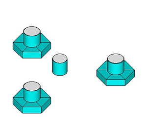
  $N \ge 3$. The examples include structures with multiple columns or floats that are equally spaced around a circle, and single cylinders with polygonal shape such as equilateral triangles or regular pentagons. Figure 1 shows three examples with
  $N = 3$.

Figure 1. Floating structures where the submerged shape is unchanged by rotation about the vertical axis through the angle  $2{\rm \pi} /3$: (a) wind-turbine floats; (b) equilateral triangular cylinder; and (c) hemispheroids at 45
 $^\circ$ angles. Structures (a) and (b) are symmetric about the vertical planes that include the centre of the structure, and the centre of an outer float in (a) or a vertex in (b); structure (c) is asymmetric.
The symmetry properties to be derived here are obvious for cases such as a square cylinder or square array of circular columns, where  $N=4$, and more generally where
  $N$ is an integer multiple of 4. For these cases, translations in the
  $x$- and
  $y$-directions produce identical disturbances of the fluid in the corresponding frames of reference, and thus the opposing forces are the same. The same symmetry applies for rotational motions about the
  $x$- and
  $y$-axes. But in other cases, the fluid motions generated by translations in surge and sway or rotations in roll and pitch are fundamentally different, especially if
  $N$ is odd. This is illustrated in figure 2, which shows the radiated waves due to surge and sway motions of the triangular cylinder in figure 1(b); thus it is surprising to find that the added mass and damping are identical for these two modes.

Figure 2. Contour plots of the free-surface elevations due to oscillatory motion of the triangular cylinder shown in figure 1(b), with unit amplitude. The cylinder sides are 2 m wide by 1 m draft, the fluid depth is infinite and the wavelength in the far field is 2 m.
It is convenient to represent the added-mass and damping coefficients in matrix form, where the columns represent the modes of motion and the rows represent the components of the force and moment. For a single rigid body, the matrices are square with dimensions  $6 \times 6$. These matrices are symmetric about their principal diagonal. Alternative proofs for rotational symmetry of the added mass are presented in the following sections. The same proofs apply directly to the damping, and these are omitted for brevity. Thus the results that follow apply in the same manner to both the added mass and damping.
In § 2 the structure is defined as a single rigid body and the total force and moment are considered, acting on the entire body. Since the shape is unchanged by rotation of the coordinate system through the angle  $\theta = 2 {\rm \pi}/N$, the added-mass matrix is the same in the rotated system. The symmetry relations follow by equating the matrices in the two coordinate systems. In § 3 the force and moment acting on each angular sector are considered, when the entire structure moves as a rigid body. The proof is based on the fact that the
  $6 \times 6$ matrix for each sector is the same when the coordinate system is rotated. The symmetry relations for the entire structure follow by summing the
  $N$ matrices for the sectors. In § 4 the most general case is considered, where the structure within each sector moves as a separate body with a total of
  $6N$ modes of motion. The simple case of two-dimensional motion in an unbounded fluid is discussed in § 5, including the added mass of the equilateral triangle. Computations are presented in § 6 for the floating offshore wind turbine and the array of three hemispheroids, to confirm and illustrate the symmetry relations. The results are discussed in § 7.
2. Symmetry relations based on the total force and moment
The structure is assumed to be rigid, with six degrees of body motion. The added mass is represented by the  $6 \times 6$ matrix
  ${{{\boldsymbol{\mathsf{A}}}}}$ with coefficients
  ${{\mathsf{A}}}_{ij}$. The row index
  $i$ represents the three components of the force (
 $i=1,2,3$) and moment (
 $i=4,5,6$). The column index
  $j$ represents the modes of translation (
 $j=1,2,3$) and rotation (
 $j=4,5,6$). These are defined with respect to the Cartesian coordinate system
  ${\boldsymbol x}=(x,y,z)$, with the
  $z$-axis vertical. The matrix
  ${{{\boldsymbol{\mathsf{A}}}}}$ is symmetric, with
  ${{\mathsf{A}}}_{ij}={{\mathsf{A}}}_{ji}$.
The origin of the coordinate system  ${\boldsymbol x}$ is located such that the vertical
  $z$-axis coincides with the axis of rotational symmetry. The vertical position of the origin is arbitrary.
A second coordinate system  ${\boldsymbol x}^*$ is introduced by rotation about the
  $z$-axis through the angle
  $\theta$. Thus
  ${\boldsymbol x} = {{{\boldsymbol{\mathsf{Q}}}}} {\boldsymbol x}^*$ and
  ${\boldsymbol x}^* = {{{\boldsymbol{\mathsf{Q}}}}}^{\rm T} {\boldsymbol x}$, where the transformation matrix
  ${{{\boldsymbol{\mathsf{Q}}}}}$ is defined by
 \begin{equation}
{{{{\boldsymbol{\mathsf{Q}}}}}} = \left[\begin{matrix}
\cos \theta & -{\sin\theta} &
0 \\ \sin \theta & \cos \theta & 0 \\ 0 & 0 & 1
\end{matrix}\right],
\end{equation}
\begin{equation}
{{{{\boldsymbol{\mathsf{Q}}}}}} = \left[\begin{matrix}
\cos \theta & -{\sin\theta} &
0 \\ \sin \theta & \cos \theta & 0 \\ 0 & 0 & 1
\end{matrix}\right],
\end{equation}
and  ${{{\boldsymbol{\mathsf{Q}}}}}^{\rm T}$ is its transpose. The same transformations apply to any vector
  ${\boldsymbol v}$ and the corresponding vector
  ${\boldsymbol v}^*$ in the rotated system. It is convenient hereafter to abbreviate
  $c = \cos \theta$ and
  $s = \sin \theta$. Thus
 \begin{equation} {{{{\boldsymbol{\mathsf{Q}}}}}} = \left[\begin{matrix} c & -s & 0 \\ s & c & 0 \\ 0 & 0 & 1 \end{matrix}\right] , \quad {{{{\boldsymbol{\mathsf{Q}}}}}^{\rm T}} = \left[\begin{matrix} c & s & 0 \\ -s & c & 0 \\ 0 & 0 & 1 \end{matrix}\right] .\end{equation}
 The matrix  ${{{\boldsymbol{\mathsf{A}}}}}$ can be partitioned into four
  $3\times 3$ submatrices
  ${{{\boldsymbol{\mathsf{A}}}}}_{mn}$, and similarly for the matrix
  ${{{\boldsymbol{\mathsf{A}}}}}^*$ in the rotated coordinate system:
 \begin{equation} {{{\boldsymbol{\mathsf{A}}}} } = \left[\begin{matrix} {{{\boldsymbol{\mathsf{A}}}} }_{11} & { {{\boldsymbol{\mathsf{A}}}} }_{12} \\ {{{\boldsymbol{\mathsf{A}}}} }_{21} & {{{\boldsymbol{\mathsf{A}}}} }_{22} \end{matrix} \right] , \quad {{{\boldsymbol{\mathsf{A}}}}^*} = \left[\begin{matrix} {{{\boldsymbol{\mathsf{A}}}}}^*_{11} & {{{\boldsymbol{\mathsf{A}}}}}^*_{12} \\ {{{\boldsymbol{\mathsf{A}}}}}^*_{21} & {{{\boldsymbol{\mathsf{A}}}}}^*_{22} \end{matrix} \right] . \end{equation}
The force  ${\boldsymbol F}$ and moment
  ${\boldsymbol M}$ that act on the body in response to translation and rotation with accelerations
  $(\dot {\boldsymbol U}, \dot {{\boldsymbol \Omega }})$ are represented in the two coordinate systems by the equations
 \begin{equation}
\left. \begin{array}{c}
{\boldsymbol F}={-}{{{\boldsymbol{\mathsf{A}}}}
}_{11}\dot{\boldsymbol U} - {{{\boldsymbol{\mathsf{A}}}}
}_{12}\dot{{\boldsymbol \Omega}} , \quad {\boldsymbol
F}^*={-} {{{\boldsymbol{\mathsf{A}}}}}^*_{11}\dot{\boldsymbol U}^* -
{{{\boldsymbol{\mathsf{A}}}}}^*_{12}\dot{{\boldsymbol \Omega}}^* , \\
{\boldsymbol M}={-} {{{\boldsymbol{\mathsf{A}}}}
}_{21}\dot{\boldsymbol U} - {{{\boldsymbol{\mathsf{A}}}}
}_{22}\dot{{\boldsymbol \Omega}}, \quad {\boldsymbol
M}^*={-} {{{\boldsymbol{\mathsf{A}}}}}^*_{21}\dot{\boldsymbol U}^* -
{{{\boldsymbol{\mathsf{A}}}}}^*_{22}\dot{{\boldsymbol \Omega}}^* .
\end{array}\right\} \end{equation}
\begin{equation}
\left. \begin{array}{c}
{\boldsymbol F}={-}{{{\boldsymbol{\mathsf{A}}}}
}_{11}\dot{\boldsymbol U} - {{{\boldsymbol{\mathsf{A}}}}
}_{12}\dot{{\boldsymbol \Omega}} , \quad {\boldsymbol
F}^*={-} {{{\boldsymbol{\mathsf{A}}}}}^*_{11}\dot{\boldsymbol U}^* -
{{{\boldsymbol{\mathsf{A}}}}}^*_{12}\dot{{\boldsymbol \Omega}}^* , \\
{\boldsymbol M}={-} {{{\boldsymbol{\mathsf{A}}}}
}_{21}\dot{\boldsymbol U} - {{{\boldsymbol{\mathsf{A}}}}
}_{22}\dot{{\boldsymbol \Omega}}, \quad {\boldsymbol
M}^*={-} {{{\boldsymbol{\mathsf{A}}}}}^*_{21}\dot{\boldsymbol U}^* -
{{{\boldsymbol{\mathsf{A}}}}}^*_{22}\dot{{\boldsymbol \Omega}}^* .
\end{array}\right\} \end{equation}
It follows that
 \begin{equation} {{{\boldsymbol{\mathsf{A}}}}^*} = \left[\begin{matrix} {{{\boldsymbol{\mathsf{A}}}}^*}_{11} & {{{\boldsymbol{\mathsf{A}}}}^*}_{12} \\ {{{\boldsymbol{\mathsf{A}}}}^*}_{21} & {{{\boldsymbol{\mathsf{A}}}}^*}_{22} \end{matrix} \right] = \left[\begin{matrix} {{{\boldsymbol{\mathsf{Q}}}}}^{\rm T}{{{\boldsymbol{\mathsf{A}}}}}_{11}{{{\boldsymbol{\mathsf{Q}}}}} & {{{\boldsymbol{\mathsf{Q}}}}}^{\rm T}{{{\boldsymbol{\mathsf{A}}}}}_{12}{{{\boldsymbol{\mathsf{Q}}}}} \\ {{{\boldsymbol{\mathsf{Q}}}}}^{\rm T} {{{\boldsymbol{\mathsf{A}}}}}_{21}{{{\boldsymbol{\mathsf{Q}}}}} & {{{\boldsymbol{\mathsf{Q}}}}}^{\rm T}{{{\boldsymbol{\mathsf{A}}}}}_{22} {{{\boldsymbol{\mathsf{Q}}}}} \\ \end{matrix} \right] .\end{equation}
Here  ${{{\boldsymbol{\mathsf{Q}}}}}$ transforms
  ${\dot {\boldsymbol U}}$ and
  ${\dot {{\boldsymbol \Omega }}}$ from
  ${\boldsymbol x}^*$ to
  ${\boldsymbol x}$ and
  ${{{{\boldsymbol{\mathsf{Q}}}}}}^\textrm {T}$ transforms the force and moment back to the
  ${\boldsymbol x}^*$ system. After evaluating the matrix products in (2.5) the first submatrix is given by
 \begin{align} {{{\boldsymbol{\mathsf{A}}}}}^*_{11} = \left[\begin{matrix} {{\mathsf{A}}}_{11}c^2{+}{{\mathsf{A}}}_{12}sc{+}{{\mathsf{A}}}_{21}sc{+}{{\mathsf{A}}}_{22}s^2 & -{{\mathsf{A}}}_{11}sc{+}{{\mathsf{A}}}_{12}c^2{-}{{\mathsf{A}}}_{21}s^2{+}{{\mathsf{A}}}_{22}sc & {{\mathsf{A}}}_{13}c{+}{{\mathsf{A}}}_{23} s \\ -{{\mathsf{A}}}_{11}cs{-}{{\mathsf{A}}}_{12}s^2{+}{{\mathsf{A}}}_{21}c^2{+}{{\mathsf{A}}}_{22}cs & {{\mathsf{A}}}_{11}s^2{-}{{\mathsf{A}}}_{12}cs{-}{{\mathsf{A}}}_{21}sc{+}{{\mathsf{A}}}_{22}c^2 & -{{\mathsf{A}}}_{13}s{+}{{\mathsf{A}}}_{23} c \\ {{\mathsf{A}}}_{31}c{+}{{\mathsf{A}}}_{32}s & -{{\mathsf{A}}}_{31}s{+}{{\mathsf{A}}}_{32}c & {{\mathsf{A}}}_{33} \\ \end{matrix} \right] .\end{align}
 Since the shape of the structure is unchanged by rotation through the angle  $\theta = 2{\rm \pi} /N$, rotation of the coordinates through the same angle does not change the added-mass matrix. Thus
  ${{{\boldsymbol{\mathsf{A}}}}}^*_{11}$ =
  ${{{\boldsymbol{\mathsf{A}}}}}_{11}$. Equating the coefficients in these two submatrices gives a set of equations, which can be reduced to the following forms if
  $s \ne 0$:
 \begin{equation} \left. \begin{matrix} ({{\mathsf{A}}}_{11} - {{\mathsf{A}}}_{22})s - ({{\mathsf{A}}}_{12} + {{\mathsf{A}}}_{21})c = 0, \\ ({{\mathsf{A}}}_{11} - {{\mathsf{A}}}_{22})c + ({{\mathsf{A}}}_{12} + {{\mathsf{A}}}_{21})s = 0, \\ \end{matrix} \right\} \quad \left. \begin{matrix} {{\mathsf{A}}}_{13}(1 - c)-{{\mathsf{A}}}_{23}s = 0, \\ {{\mathsf{A}}}_{13}s+{{\mathsf{A}}}_{23}(1 - c) = 0. \\ \end{matrix} \right\} \end{equation}
These equations are homogeneous and the determinants  $s^2+c^2$ and
  $s^2+(1-c)^2$ are non-zero. Thus
 \begin{equation} {{\mathsf{A}}}_{11}-{{\mathsf{A}}}_{22} = 0, \quad {{\mathsf{A}}}_{12}+{{\mathsf{A}}}_{21} = 0, \quad {{\mathsf{A}}}_{13}=0, \quad {{\mathsf{A}}}_{23} = 0 . \end{equation}
Following the same procedure for the other submatrices gives the results:
 $$\begin{gather} {{\mathsf{A}}}_{14}-{{\mathsf{A}}}_{25}=0, \quad {{\mathsf{A}}}_{15}+{{\mathsf{A}}}_{24} = 0, \quad {{\mathsf{A}}}_{16}=0, \quad {{\mathsf{A}}}_{26} = 0 , \end{gather}$$
 $$\begin{gather}{{\mathsf{A}}}_{41}-{{\mathsf{A}}}_{52}=0, \quad {{\mathsf{A}}}_{42}+{{\mathsf{A}}}_{51} = 0, \quad {{\mathsf{A}}}_{43}=0, \quad {{\mathsf{A}}}_{53} = 0 , \end{gather}$$
 $$\begin{gather}{{\mathsf{A}}}_{44}-{{\mathsf{A}}}_{55}=0, \quad {{\mathsf{A}}}_{45}+{{\mathsf{A}}}_{54} = 0, \quad {{\mathsf{A}}}_{46}=0, \quad {{\mathsf{A}}}_{56} = 0 . \end{gather}$$
Since  ${{{\boldsymbol{\mathsf{A}}}}}$ is symmetric,
  ${{\mathsf{A}}}_{12}={{\mathsf{A}}}_{21} = 0$ and
  ${{\mathsf{A}}}_{45}={{\mathsf{A}}}_{54} = 0$. After using (2.8)–(2.11) and imposing symmetry it follows that
 \begin{equation} {{{\boldsymbol{\mathsf{A}}}}} = \left[\begin{matrix} {{\mathsf{A}}}_{11} & 0 & 0 & {{\mathsf{A}}}_{14} & {{\mathsf{A}}}_{15} & 0 \\ 0 & {{\mathsf{A}}}_{11} & 0 & - {{\mathsf{A}}}_{15} & {{\mathsf{A}}}_{14} & 0 \\ 0 & 0 & {{\mathsf{A}}}_{33} & 0 & 0 & {{\mathsf{A}}}_{36} \\ {{\mathsf{A}}}_{14} & - {{\mathsf{A}}}_{15} & 0 & {{\mathsf{A}}}_{44} & 0 & 0 \\ {{\mathsf{A}}}_{15} & {{\mathsf{A}}}_{14} & 0 & 0 & {{\mathsf{A}}}_{44} & 0 \\ 0 & 0 & {{\mathsf{A}}}_{36} & 0 & 0 & {{\mathsf{A}}}_{66} \\ \end{matrix} \right] .\end{equation}
 These results are based on the fact that  ${{{\boldsymbol{\mathsf{A}}}}}^* = {{{\boldsymbol{\mathsf{A}}}}}$ when
  $\theta = 2{\rm \pi} /N$, but they imply more general conclusions. Indeed, they have been derived without explicitly assigning the angle
  $\theta$ of the rotated coordinate system. Since (2.7a,b) are homogeneous, the solutions (2.8) do not depend on
  $\theta$, and similarly for (2.9)–(2.11). Thus the matrix
  ${{{\boldsymbol{\mathsf{A}}}}}^*$ is independent of
  $\theta$. Alternatively,
  $\theta = 2{\rm \pi} /N$ can be assigned explicitly throughout the steps leading to (2.12); if (2.5) is then used to transform this matrix with rotation through an arbitrary angle
  $\theta$, the result is identical to (2.5). Thus the added mass and damping are independent of the angle of rotation of the coordinate system, as in the case of an axisymmetric structure.
In most cases of practical interest, the shape of the structure is symmetric about  $N$ vertical planes, as in figure 1(a,b). It is logical, then, to define the coordinates such that the
  $x$-axis lies in a plane of symmetry with
  $y=0$ in the same plane. It then follows that surge and roll are uncoupled, and similarly for heave and pitch. Thus
  ${{\mathsf{A}}}_{14}=0$ and
  ${{\mathsf{A}}}_{36}=0$. In that case the only difference in (2.12) relative to an axisymmetric structure is the non-zero coefficient
  ${{\mathsf{A}}}_{66}$, representing the added moment of inertia due to rotation about the vertical axis. The only non-zero coupling is between surge and pitch (
 ${{\mathsf{A}}}_{15}$) and between sway and roll (
 ${{\mathsf{A}}}_{24}$). It is evident from (2.12) that these are equal in magnitude with opposite signs. In general, they are non-zero, as in the axisymmetric case, depending on the vertical position of the origin.
Since the case  $N=2$ has been excluded, the restriction that
  $\sin \theta$ is non-zero is justified in (2.7a,b) and these equations are non-singular. If
  $N=2$ and the coordinate system is rotated through the angle
  ${\rm \pi}$, the only effect is to change the signs of the coupling coefficients in the third row or column of each submatrix. Thus the equality
  ${{{\boldsymbol{\mathsf{A}}}}}^*={{{\boldsymbol{\mathsf{A}}}}}$ does not provide any relations between different elements of the added-mass matrix and no conclusions can be reached analogous to (2.8)–(2.12) except that there is no coupling between horizontal and vertical modes.
3. The force and moment on each sector of a rigid structure
A triangular array with  $N=3$ identical bodies is considered to simplify the analysis. The bodies are centred on a circle at polar angles
  $\theta _n = (n-1)(2{\rm \pi} /3)$ (
 $n=1,2,3$) or, equivalently, at
  $\theta =0$ and
  $\theta =\pm (2{\rm \pi} /3)$. The entire structure moves as a rigid body with six degrees of freedom, as in § 2. The added mass corresponding to the force and moment on the body
  $n$ is represented by the
  $6\times 6$ matrix
  ${\boldsymbol a}^{(n)}$ with coefficients
  $a^{(n)}_{ij}$. In general, these matrices are full and asymmetric. The matrix for the entire structure is
 \begin{equation} {{{\boldsymbol{\mathsf{A}}}}} = {\boldsymbol a}^{(1)} + {\boldsymbol a}^{(2)} + {\boldsymbol a}^{(3)} .\end{equation}
 Following a similar procedure as in § 2, the force and moment acting on body  $n$ can be evaluated from
  ${\boldsymbol a}^{(n)}$ in the
  ${\boldsymbol x}$ system, or from
  ${\boldsymbol a}^{(n)*}$ in the rotated system
  $\theta = \theta _n$. Since
  ${\boldsymbol a}^{(n)*} = {\boldsymbol a}^{(1)}$, it follows for
  $(n=2,3)$ that the force
  ${\boldsymbol f}^{(n)}$ on body
  $n$ is given by the alternative expressions
 \begin{equation} {\boldsymbol
f}^{(n)}={-}{\boldsymbol a}_{11}^{(n)} \dot{\boldsymbol U}
-{\boldsymbol a}_{12}^{(n)} \dot{{\boldsymbol \Omega}} ,
\quad \quad {\boldsymbol f}^{(n)*}={-}{\boldsymbol
a}_{11}^{(1)} \dot{\boldsymbol U}^*-{\boldsymbol
a}_{12}^{(1)} \dot{{\boldsymbol \Omega}}^* ,
\end{equation}
\begin{equation} {\boldsymbol
f}^{(n)}={-}{\boldsymbol a}_{11}^{(n)} \dot{\boldsymbol U}
-{\boldsymbol a}_{12}^{(n)} \dot{{\boldsymbol \Omega}} ,
\quad \quad {\boldsymbol f}^{(n)*}={-}{\boldsymbol
a}_{11}^{(1)} \dot{\boldsymbol U}^*-{\boldsymbol
a}_{12}^{(1)} \dot{{\boldsymbol \Omega}}^* ,
\end{equation}
and similarly for the moment. Since  ${\boldsymbol f}^{(n)}={{{\boldsymbol{\mathsf{Q}}}}}\,{\boldsymbol f}^{(n)*}$ and
  $( \dot {\boldsymbol U}^*, \dot {{\boldsymbol \Omega }}^*)={{{\boldsymbol{\mathsf{Q}}}}}^\textrm {T} ( \dot {\boldsymbol U}, \dot {{\boldsymbol \Omega }})$, it follows from (3.2a,b) that
 \begin{equation} {\boldsymbol a}^{(n)} = \left[\begin{matrix} {\boldsymbol a}^{(n)}_{11} & {\boldsymbol a}^{(n)}_{12} \\[3pt] {\boldsymbol a}^{(n)}_{21} & {\boldsymbol a}^{(n)}_{22} \end{matrix} \right] = \left[\begin{matrix} {{{{\boldsymbol{\mathsf{Q}}}}}}_n{\boldsymbol a}^{(1)}_{11}{{{\boldsymbol{\mathsf{Q}}}}}_n^{\rm T} & {{{{\boldsymbol{\mathsf{Q}}}}}_n}{\boldsymbol a}^{(1)}_{12}{{{\boldsymbol{\mathsf{Q}}}}}_n^{\rm T} \\[3pt] {{{{\boldsymbol{\mathsf{Q}}}}}_n} {\boldsymbol a}^{(1)}_{21}{{{\boldsymbol{\mathsf{Q}}}}}_n^{\rm T} & {{{{\boldsymbol{\mathsf{Q}}}}}_n}{\boldsymbol a}^{(1)}_{22} {{{\boldsymbol{\mathsf{Q}}}}}_n^{\rm T} \\ \end{matrix} \right],\end{equation}
where  ${{{\boldsymbol{\mathsf{Q}}}}}_n$ and
  ${{{\boldsymbol{\mathsf{Q}}}}}_n^\textrm {T}$ are defined by (2.2a,b) with
  $\theta =\theta _n$.
In the following equations, it is convenient to omit the superscript 1 for the coefficients of the matrix  ${\boldsymbol a}^{(1)}$. Thus
  $a_{ij} \equiv a^{(1)}_{ij}$. After the indicated multiplications, the results are similar to (2.6) except for the signs of terms that are linear in
  $s=\sin \theta _n$. However, these terms cancel when the sum in (3.1) is evaluated, since
  $\sin \theta _3 = -{\sin \theta _2}$, and the first submatrix of
  ${{{\boldsymbol{\mathsf{A}}}}}$ is given by
 \begin{equation} {{{\boldsymbol{\mathsf{A}}}}}_{11} =\left[\begin{matrix} a_{11} & a_{12} & a_{13} \\ a_{21} & a_{22} & a_{23} \\ a_{31} & a_{32} & a_{33} \\ \end{matrix} \right] + 2 \left[\begin{matrix} a_{11}c^2 + a_{22}s^2 & a_{12}c^2 - a_{21}s^2 & a_{13}c \\ -a_{12}s^2 + a_{21}c^2 & a_{11}s^2 + a_{22}c^2 & a_{23} c \\ a_{31}c & a_{32}c & a_{33} \\ \end{matrix} \right] . \end{equation}
After substituting  $c = \cos (2{\rm \pi} /3) = -1/2$,
  $c^2 = 1/4$,
  $s^2 = 3/4$, and combining the two matrices in (3.4),
 \begin{equation} {{{\boldsymbol{\mathsf{A}}}}}_{11} = \frac{3}{2}\left[\begin{matrix} a_{11} + a_{22} & a_{12} - a_{21} & 0 \\ a_{21} - a_{12} & a_{11} + a_{22} & 0 \\ 0 & 0 & 2a_{33} \end{matrix} \right] .\end{equation}
Thus
 $$\begin{gather} A_{11}=A_{22}={\tfrac{3}{2}} (a_{11}+a_{22}), \end{gather}$$
 $$\begin{gather}A_{33}=3 a_{33} . \end{gather}$$
Since  ${{{\boldsymbol{\mathsf{A}}}}}$ is symmetric,
  $a_{12}-a_{21}=0$ and it follows that
 \begin{equation} A_{12}=A_{21}=0 . \end{equation}
Repeating the same process for the other submatrices gives the results
 $$\begin{gather} A_{44}=A_{55}={\tfrac{3}{2}} (a_{44}+a_{55}) , \end{gather}$$
 $$\begin{gather}A_{66}=3 a_{66} , \end{gather}$$
 $$\begin{gather}A_{14}=A_{25}=A_{41}=A_{52}={\tfrac{3}{2}} (a_{14}+a_{25})={\tfrac{3}{2}} (a_{41}+a_{52}) , \end{gather}$$
 $$\begin{gather}A_{15}={-}A_{24}=A_{51}={-}A_{42}={\tfrac{3}{2}} (a_{15}-a_{24})={\tfrac{3}{2}} (a_{51}-a_{42}), \end{gather}$$
 $$\begin{gather}A_{36}=A_{63}=3a_{36}=3a_{63} . \end{gather}$$
The other coefficients  $A_{ij}$ not included in (3.6)–(3.13) are equal to zero. These results are consistent with (2.12).
This analysis has been described for three separate bodies, but it can be applied more generally to structures such as those shown in figure 1(a,b) by dividing the submerged surface into angular sectors with included angles  $2{\rm \pi} /3$ and replacing the force and moment on each body by the force and moment due to the pressure acting on the surface in the corresponding sector. The extension for
  $N>3$ follows by summing (3.1) over all bodies or sectors. The final results are unchanged, except that the factors 3 and
  $3/2$ in (3.5)–(3.13) are replaced by
  $N$ and
  $N/2$.
4. The force and moment on separate bodies moving independently
If the structure is composed of  $N$ separate bodies, each having six independent degrees of freedom, the added mass and damping for the entire configuration are represented by matrices with dimensions
  $6N \times 6N$. The analysis is described here in the context of three separate bodies, as in § 3, but it is applicable more generally to structures such as the floating offshore wind turbine and the triangular cylinder if the structure is divided into sectors with equal included angles.
To preserve the meaning of the previous notation, the symbol  $\boldsymbol{C}$ is used here for the complete
  $18 \times 18$ matrix of added-mass coefficients
  $c_{ij}$, with nine submatrices
  $\boldsymbol{C}_{ij}$. Thus
 \begin{equation} {{{\boldsymbol{\mathsf{C}}}}} = \left[\begin{matrix} {{{\boldsymbol{\mathsf{C}}}}}_{11} & {{{\boldsymbol{\mathsf{C}}}}}_{12} & {{{\boldsymbol{\mathsf{C}}}}}_{13} \\ {{{\boldsymbol{\mathsf{C}}}}}_{21} & {{{\boldsymbol{\mathsf{C}}}}}_{22} & {{{\boldsymbol{\mathsf{C}}}}}_{23} \\ {{{\boldsymbol{\mathsf{C}}}}}_{31} & {{{\boldsymbol{\mathsf{C}}}}}_{32} & {{{\boldsymbol{\mathsf{C}}}}}_{33} \\ \end{matrix} \right] .\end{equation}
Here  $\boldsymbol{C}_{ii}$ is the
  $6 \times 6$ matrix for body
  $i$ due to its own motions with the other bodies fixed, and
  $\boldsymbol{C}_{ij}$ represents the force and moment on body
  $i$ due to the motions of body
  $j$. The matrix
  $\boldsymbol{C}$ is symmetric, with
  $c_{ij}=c_{ji}$. Thus the submatrices
  $\boldsymbol{C}_{ii}$ are symmetric but
  $\boldsymbol{C}_{ij}$ is asymmetric if
  $i \ne j$.
The matrix  ${\boldsymbol a}^{(n)}$ defined in § 3 represents the force and moment acting on body
  $n$ when all three bodies have the same motions. It follows that
 \begin{equation} {\boldsymbol a}^{(n)} = {{{\boldsymbol{\mathsf{C}}}}}_{n1} + {{{\boldsymbol{\mathsf{C}}}}}_{n2} + {{{\boldsymbol{\mathsf{C}}}}}_{n3} .\end{equation}
 An alternative to the approach in § 3 is to consider the force and moment on the entire structure with separate motions for each body. In this case there are six components of the force and moment and 18 modes of motion. The matrix  ${{\boldsymbol \alpha }}^{(n)}$ is defined to represent the force and moment on the entire structure due to motions of body
  $n$ with the others fixed. In this case
 \begin{equation} {{\boldsymbol \alpha}}^{(n)} = {{{\boldsymbol{\mathsf{C}}}}}_{1n} + {{{\boldsymbol{\mathsf{C}}}}}_{2n} + {{{\boldsymbol{\mathsf{C}}}}}_{3n} .\end{equation}
Since  $\boldsymbol{C}$ is symmetric, it follows from (4.2) and (4.3) that
  ${{\boldsymbol \alpha }}^{(n)}$ is the transpose of
  ${\boldsymbol a}^{(n)}$.
The relations (3.1) and (3.3) apply to both  ${\boldsymbol a}^{(n)}$ and
  ${{\boldsymbol \alpha }}^{(n)}$. This can be confirmed directly, or from the fact that
  ${{\boldsymbol \alpha }}^{(n)}$ is the transpose of
  ${\boldsymbol a}^{(n)}$. Thus the proof of rotational symmetry in § 3 can be based on either the force and moment acting on each separate body when they move together or the total force and moment when each body moves independently.
5. Added mass of cylinders in two dimensions
The simplest application of the symmetry relations is in two dimensions, with the body geometry and flow field independent of  $z$. If the body profile has periodic rotational symmetry, the only non-zero added-mass coefficients are
  $A_{11}=A_{22}$ and
  $A_{66}$. The examples include equilateral triangles and circular arrays of identical profiles.
The added mass of the equilateral triangle has been studied by Goldschmidt & Protos (Reference Goldschmidt and Protos1968), including both experimental and theoretical results for the ratio  $A_{11}/\rho S$, where
  $\rho$ is the fluid density and
  $S$ is the area of the triangle. The experimental value given is 1.57. Their theoretical value
  $A_{11}/\rho S =1.53$ is based on a simplified analysis using the conformal mapping of an approximation to the triangle with continuous curvature and rounded vertices. If the conformal transformation for the triangle is used without approximation, and integrated numerically, we find that the correct theoretical value is 1.581. It is noted by Goldschmidt & Protos (Reference Goldschmidt and Protos1968) that ‘the angle of attack isn't of concern in computing the kinetic energy’, implying that the added mass is the same in all directions. No other references have been found that refer to this topic.
6. Examples of computational results
Results are shown here for the added mass and damping of the floating offshore wind turbine in figure 1(a) and the hemispheroids in figure 1(c). The forces, moments and modes of motion are defined with respect to the coordinate system  ${\boldsymbol x}$ with the origin at the centre of the structure, in the plane of the free surface, and the
  $z$-axis positive upwards. The centres of the outer floats or hemispheroids are on a circle of radius
  $R_c$ in the plane
  $z=0$, at polar angles
  $\theta _n = (n-1)(2{\rm \pi} /3)$ (
 $n=1,2,3$). The added-mass coefficients are non-dimensionalized by the displaced mass
  $\rho V$ and the damping by
  $\rho V \omega$, where
  $\rho$ is the fluid density,
  $V$ is the volume and
  $\omega$ is the frequency. The cross-coupling coefficients are non-dimensionalized by the additional factor
  $R_c$ and the moments due to rotation by
  $R_c^2$. The gravitational acceleration
  $g=9.80665$ m
 $^2$ s
 $^{-1}$ is assigned.
Figure 3 shows the coefficients for surge and sway motions of the floating offshore wind turbine over a range of the frequency  $\omega$. The coefficients for surge are shown by solid lines and for sway by circular symbols. It is apparent that these coefficients have the same values for all frequencies. The complete matrices
  ${{{\boldsymbol{\mathsf{A}}}}}$ and
  ${{{\boldsymbol{\mathsf{B}}}}}$ are shown in table 1 for
  $\omega =1$ rad s
 $^{-1}$. For this structure,
  $R_c = 23.9$ m and
  $V=2612.12$ m
 $^3$. The outer floats have a total draft of 9.185 m, including upper cylinders of radius 3.6 m and depth 5.885 m, and lower skirts with six rectangular sides 8.1 m wide by 3.3 m high. The radius of the inner cylinder is 3.15 m and the draft is 6.6 m. The fluid depth is 65 m.

Figure 3. Added-mass ( $A_{ii}$) and damping (
 $B_{ii}$) coefficients of the floating offshore wind-turbine floats shown in figure 1(a).
Table 1. Added-mass ( ${{{\boldsymbol{\mathsf{A}}}}}$) and damping (
 ${{{\boldsymbol{\mathsf{B}}}}}$) coefficients for the floating offshore wind-turbine configuration shown in figure 1(a).

Table 2 shows the coefficients for the configuration of three hemispheroids. This is intended to illustrate the general case of an asymmetric structure. The hemispheroids are prolate, with length 3 m, maximum radius 0.5 m,  $V=2.3562$ m
 $^3$ and
  $R_c=2$ m. The major axis of each hemispheroid is in the plane of the free surface, oriented at
  $45^{\circ }$ from the tangent to the circle that includes the centres. The calculations are performed for infinite fluid depth at the wavenumber
  $K=\omega ^2/g=1\ \textrm {m}^{-1}$.
Table 2. Added-mass ( ${{{\boldsymbol{\mathsf{A}}}}}$) and damping (
 ${{{\boldsymbol{\mathsf{B}}}}}$) coefficients for the three hemispheroids shown in figure 1(c).

The matrices in tables 1 and 2 have the same form as the matrix (2.12). Since the floating offshore wind-turbine configuration is symmetric, the coefficients  $A_{14}$,
  $A_{25}$ and
  $A_{36}$ are zero in table 1, and likewise for
  $B_{14}$,
  $B_{25}$ and
  $B_{36}$. These coefficients are non-zero in table 2 since the configuration with three hemispheroids is asymmetric.
The coefficients in tables 1 and 2 have been computed using the higher-order panel method described by Lee & Newman (Reference Lee and Newman2005, pp. 226–228). The geometry is defined analytically, without approximation, and the potential on the body surface is represented by continuous B-splines. Non-uniform mapping is used for the floating offshore wind turbine to account for the singularities at the corners of the skirts. A sequence of progressively smaller panels are used, and extrapolated linearly to zero to achieve the final results. The estimated accuracy is  ${\pm }0.0002$ for the added-mass coefficients in table 1 and
  ${\pm }0.0001$ for the damping coefficients in table 1 and all coefficients in table 2.
There is supplementary material available at https://doi.org/10.1017/jfm.2022.709 that includes the matrices  $\boldsymbol{C}$,
  ${\boldsymbol a}^{(n)}$ and
  ${{\boldsymbol \alpha }}^{(n)}$ for both structures, as defined in §§ 3 and 4.
7. Discussion
Structures with periodic angular shape have been considered, where the geometry is unchanged by rotation about the vertical axis through an angle  $2{\rm \pi} /N$, with the integer
  $N\ge 3$. For this type of structure, the added-mass and damping coefficients for surge and sway are equal, and uncoupled. The same properties apply for roll and pitch. The general form of the coefficients is shown in the matrix (2.12). If the structure is symmetric about a vertical plane, as in most cases of practical importance, the only difference compared to an axisymmetric structure is the non-zero moment due to rotation about the vertical axis.
These properties apply only to the force and moment due to body motions, and not to the exciting force and moment due to incident waves or other characteristics such as the radiated wave patterns shown in figure 2. However, there are integral relations that apply. For example, the rate of energy flux in the radiated waves is related to the damping coefficients; thus the integral of the square of the wave amplitude around a circle of large radius has the same value for the two wave patterns shown in figure 2. Similarly, the integral of the square of the exciting forces and moments over all incident-wave directions can be related to the damping coefficients using the Haskind relations (Newman Reference Newman2017, pp. 315–316); thus these integrals have the same value for the exciting forces in surge and sway or the moments in roll and pitch.
The case  $N=2$ is an exception. When
  $\theta ={\rm \pi}$ the coordinate rotation simply changes the signs of the horizontal coordinates, modes, forces and moments, providing no relations between the coefficients for different modes. A vertical flat plate in the plane
  $y=0$ is an obvious example where (2.12) is not valid, since the added mass and damping are zero for surge and non-zero for sway.
The principal result of this work is to show that the added-mass and damping matrices have the relatively simple forms shown in (2.12) if the structure has periodic angular shape. One of the referees has posed the inverse problem: If the matrix is of the same form as (2.12), does it follow that the structure necessarily has periodic angular shape? This is an interesting question, at least from the intellectual standpoint, which is left for future work.
Supplementary material
Supplementary material is available at https://doi.org/10.1017/jfm.2022.709.
Funding
This research received no specific grant from any funding agency, commercial or not-for-profit sectors.
Declaration of interests
The authors report no conflict of interest.


 Open access