


Abstract
A comparative analysis is performed of the electron emission characteristics as the electrons move in laser fields with ultra-relativistic intensity and different configurations corresponding to a plane or tightly focused wave. For a plane travelling wave, analytical expressions are derived for the emission characteristics, and it is shown that the angular distribution of the radiation intensity changes qualitatively even when the wave intensity is much less than that in the case of the radiation-dominated regime. An important conclusion is drawn that the electrons in a travelling wave tend to synchronised motion under the radiation reaction force. The characteristic features of the motion of electrons are found in a converging dipole wave, associated with the curvature of the phase front and nonuniformity of the field distribution. The values of the maximum achievable longitudinal momenta of electrons accelerated to the centre, as well as their distribution function are determined. The existence of quasi-periodic trajectories near the focal region of the dipole wave is shown, and the characteristics of the emission of both accelerated and oscillating electrons are analysed.
Export citation and abstract BibTeX RIS
1. Introduction
Progress in the field of laser technology in recent years has made it possible to offer a number of large-scale projects to design ultra-high-power (at a level of  and higher) laser systems [1–3]. The interaction of optical fields produced by radiation from these systems with matter has a number of new fundamental features, including the important radiation reaction force [4, 5].
This article analyses the characteristics of acceleration and emission of charged particles (electrons) in the field of a plane linearly polarised wave and an incident dipole wave, when the influence of the radiation reaction force leads to qualitatively new effects in the interaction dynamics. In the case of a plane wave, which is in a sense a reference, we consider the formally negelcted emission, which qualitatively depend on the presence of reaction forces. We also analyse in detail the processes of acceleration and emission in a converging dipole wave [6], which allows one to reach the maximum possible amplitude of the field at a given laser radiation power. In this more complicated case, it is found that the curvature of the wavefront affects the motion of charged particles, which leads to significant quantitative changes in the characteristics of the accelerated particles in comparison with the case of a plane wave. In addition, the characteristics of the electron emission, which strongly depend on the type of the realised trajectories, are described.
2. Electron motion and emission in the field of a plane linearly polarised wave
As is known, the relativistic equation of motion with the radiation reaction force for a charged particle taken into account in a plane travelling wave has an exact analytical solution [7]. Nevertheless, a strict analysis of the emission characteristics of the particle can be made only in some extreme cases. The parameter is known [8, 9], which determines the relative importance of the effects of radiation reaction and equal to the ratio of the radiation reaction force on the period of the wave to the initial energy of the particle,
where  are the charge and mass of the particle, respectively;
  is the speed of light;
  is the angular frequency of the wave;
  (plus or minus correspond to counterpropagating and copropagating direction of the particle motion to a wave);
  is the initial relativistic factor;
  ;
;  is the initial velocity of the particle; and
  is the amplitude of the vector potential
  in relativistic units. According to (1) the dynamics of the electron in the radiation-dominated regime, when
  and, therefore, the energy loss by emission of hard photons is large, strongly depends on the mutual direction of propagation of the wave and the particle. If the wave is incident on an initially resting electron, then the radiation reaction for the particle accelerated by the wave along its propagation direction will play an important role only for the amplitudes of the field that are comparable to the amplitude of the field
where  ;
;  ;
;  is Planck's constant;
  is the fine-structure constant; and the field
  is equal to
  at a wavelength
  . The fields of this magnitude may be produced in the foreseeable future due to the implementation of the projects [1–3]. On the other hand, when an optical wave interacts with an electron moving towards this wave, the situation may change qualitatively. Thus,
  is reached for an electron with an energy of
  in the laser field with
  at a wavelength
  , which corresponds to the intensity of
  achievable today. This case is most often considered in the literature [8, 9], because it is of practical importance for generation of X-ray and gamma-rays.
However, in this section we consider the situation when the radiation parameter  is small, but, nevertheless, its account can be crucial for finding the trajectories of the particle and the properties of its emission. This situation can emerge as a result of a relatively long interaction between the particle and the wave, when the effect of the weak radiation reaction builds up over time, and eventually the particle trajectory, and hence its emission characteristics depend strongly on the radiation reaction. In Section 2.1 we consider the emission of initially resting electrons accelerated by the incident wave, for which, when the reaction force is neglected, we can determine the characteristics of the emission by the given trajectory. In this case, the emission characteristics can be represented in an analytical form and amenable to complete analysis. In section 2.2 we consider the case when the account for even a small radiation reaction force can qualitatively change the emission characteristics, namely, for a particle created at a zero electric field the angular distribution of the radiation intensity can be changed qualitatively. Finally, in Section 2.3, an important conclusion is made about the asymptotic behaviour of the electrons, which actually tend to synchronised movement under the action of the radiation reaction force.
2.1. Emission of an electron accelerated by a plane incident wave
Let us analyse first the acceleration by the incident semi-bounded plane wave

of an initially resting electron  , for which we can obtain exhaustive characteristics of emission.
With the amplitude of the field, much less than  , we can ignore the effect of radiation reaction and write the corresponding solution of the equation of motion in the parametric form:
where  ;
;  and
and  are the projections of the particle's momentum in relativistic units.
In order to characterise the emission of a particle, we use the expressions for the radiation power  , the radiation power per unit solid angle
  and characteristic radiation frequency
  [4]:
[4]:
where  and
and  are the velocity and acceleration of a particle;
  is the unit vector specifying the direction of the radiation. Equation (6) determines the centre frequency of the radiation when the particle moves along a curved trajectory. Using (3), we can find an expression for
  and
and  :
:

where  and
and  is the angle between the vector
  and the propagation direction of the incident wave in the plane
  .
.
Let us determine the direction and the corresponding moments of time, at which the electron radiates most, as well as the characteristic radiation frequency.
The function  is maximal when
  , where
  is an integer. Then, at

where  .
.
In this case, the direction of the radiation does not depend on the intensity, the electron, because at the moments of time  its acceleration and velocity are directed almost along the electric field, radiates as a dipole with a characteristic frequency

The function  is maximum when
and
Then, at  , we have
the width of the directivity pattern being equal to  , and the direction along which
  is maximum corresponding to
  (the angle is defined as the ratio of the transverse and longitudinal momenta of the particle, because in the ultrarelativistic case the particles radiate in the direction of their motion in a narrow range of angles around the velocity vector, and the width of the directivity pattern behaves as an inverse function of the gamma factor of the particle).
The function  is maximal
  , when
  and
and  ; this follows from the decomposition of
  in a series in a small angle
  due to the ultrarelativistic character of motion. In this case, the expression for the power and the characteristic frequency of the radiation coincide with (12), the maximum output power per unit solid angle is given by
the characteristic width of the directivity pattern is  , and the direction in which
  is maximum corresponds to
  .
.
Now, using relation (3) for  and
and  , the character of acceleration and emission can be described as follows. Initially, the particle is accelerated by the incident wave and emits into a fairly large solid angle, having the maximum output power (10) at the initial moment of time. Then, on the time interval
  , the particle moves at relativistic speeds, the directivity pattern gradually narrows down and is directed along its velocity of motion. The radiation power decreases to a value determined by (12), and the radiation frequency increases to the value of
  from (12). At a time
  , the output power is zero because the particle is not subjected to any force. Then, by virtue of the periodic nature of the interaction, the particle starts to slow down, the directivity pattern broadens, and the radiation power increases again to a level (10), corresponding to the stopping time of the particle. Below, the above process of particle acceleration and emission within the approximation neglecting the radiation reaction force is repeated periodically.
2.2. A special case of the influence of the radiation reaction force
Consider now the case when, despite the smallness of the parameter  , the influence of the reaction force can qualitatively change the character of motion and characteristics of radiation, respectively. For example, Di Piazza et al. [9] presented an example of interaction of an incident wave with a counterpropagating electron and showed that by selecting the wave and the particle parameters, one can change the sign of the longitudinal velocity by taking into account only the radiation reaction force. This is due to the fact that the wave itself under the action of ponderomotive forces can greatly reduce the longitudinal velocity of the electron, and therefore even account for a small radiation reaction force can turn the electron, i.e., make it move in the opposite direction. We show that this situation can be realised for the transverse projection of the velocity; however, in this case the electron at the initial moment shoudl be in the correct phase of the field. This condition can be achieved, for example, during ionisation of atoms by hard photons.
Let the electron be produced with a zero transverse momentum at a time when the field of a plane linearly polarised wave is zero. We use the general solution of the relativistic motion equation, which can be written as [7]
As is known, in the absence of the radiation reaction force such an electron obtains a maximum constant component of the transverse momentum, so that the transverse momentum is always negative  . Account for the radiation reaction will lead to the fact that at some point in time, the projection of the transverse momentum changes the sign, i.e., the electron will turn around and move in the opposite direction. Assuming
  , one can easily see this from the solution of (14), taking into account that
  at
at  .
.
We use expression (5) and construct the angular distribution of the radiation power of the electron produced at a zero field. The azimuthal angle is measured from the direction of the electric field at the initial time. As follows from the comparison of the curves in Fig. 1, the effect of the radiation reaction force leads to a qualitative change in the angular distribution of the radiation intensity, which is due to differences in the behaviour of the electron motion.
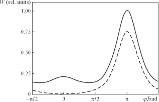
Figure 1. Azimuthal angle  as a function of the energy
  radiated by an electron produced at a zero field during its lag behind the wave by 20 field cycles with (solid line) and without (dashed line) radiation reaction taken into account. Dimensionless vector potential amplitude is
  and
and  .
.
Download figure:
Standard image2.3. Synchronisation of electron motion by the radiation reaction force
Here, we pay particular attention to the fact that the general form of the solution of the relativistic motion equations (14) in the field of a plane travelling wave with the radiation reaction force in the Landau–Lifshitz form allows one to make a fundamentally important conclusion. Indeed, it is easy to see that in the general solution all the trajectories tend to a limit, which corresponds to the trajectory of an electron produced at the zero vector potential of the wave or at the maximum of the electric field. This conclusion not only confirms the theorem on the phase space compressibility of particles interacting with the laser field, taking into account the radiation reaction force [10, 11], but also leads to an even more important statement about the asymptotic synchronisation of the motion of all particles. The trajectory of this limiting motion has an average value of the transverse momentum, equal to zero [ at
at  ), and, in particular, can be obtained from equation (14). Assuming
  , we obtain
As is easily seen, the electron in the field of the incident linearly polarised wave is accelerated in the direction of its propagation and its average energy is proportional to  , because
  and
and  at
at  . Note for comparison that in a circularly polarised wave the energy is proportional to
  [12].
[12].
3. Electron motion and radiation in a converging dipole wave
Consider the case of tightly focused laser radiation in the form of an optical wave of dipole configuration. This configuration is of interest because it allows one, at a given power of the laser radiation source in the focal region of size  , to create a field with the highest intensity in comparison with other focusing geometries. As will be shown below, the relativistic dynamics of an electron in the field of a converging dipole wave has a number of interesting and important applied properties. Unlike the case of a plane wave, the motion of the electron carried away by the dipole wave will depend on its initial position with respect to the centre of the converging wave. The question arises: When is the emission of electron radiation most effective and, therefore, the effect of the radiation reaction force maximal? According to equation (1) and the previous arguments, it is natural to expect that the maximum radiation burst will occur in the central region for those electrons that have acquired the largest longitudinal momentum in the converging wave and met the diverging wave reflected from the centre. For the analysis of the acquired longitudinal momentum we first consider a model problem with a sharp switching on of the field, which can have a relatively simple physical interpretation. Then, we turn our attention to a realistic pulse with a smooth envelope.
3.1. Incident pulse with a sharp switching on of the field
Let the centre of the converging dipole wave be located at the origin of the Cartesian coordinate system. Then, the expressions for the electric and magnetic fields of the dipole wave can be given in the form [6]


where  is the radius vector from the focusing point to the observation point with
  and
and  ;
;  ;
;  is an arbitrary constant vector, the modulus of which is related to the dipole wave power
  ; and
; and  . Consider the trajectory of the particles and compare them with the trajectories in the case of a plane wave. It is useful to bear in mind that the amplitude of the incident dipole wave along its propagation axis is related to the power as follows:
As in Section 2, we assume that the electrons are initially at rest and a semibounded radiation pulse with a sharp switching on of the field is incident on them, so that

where  . For the analysis it is sufficient to consider the behaviour of electrons within the half-cycle of the wave, during which they must lag behind by half of the wavelength from the leading edge of the pulse.
As is known, in the field of a plane wave an initially resting electron acquires a longitudinal momentum  along the propagation direction of the wave and shifts in the transverse direction with a transverse momentum
  [4], where
  is the dimensionless vector potential at a point where the particle is located. We take as the amplitude of the vector potential of a plane wave
  its value corresponding to the amplitude of the incident dipole wave at a point of the initial location of the electron
  . Figure 2 shows the electron trajectories for two different wave powers,
  and
and  ; one can see that they are qualitatively similar, and this is an evidence of the role of small radiation reaction force for the electrons accelerated to the centre. However, the accelerations of the electrons in the propagation directions of the dipole and the plane waves are qualitatively different: the rate of acceleration and achievable values of the longitudinal momentum in a converging dipole wave are much lower than in the plane wave, despite the fact that the converging wave amplitude increases rapidly to the centre. This is due, primarily, to the curvature of the phase front of the dipole wave, and to the transverse nonuniformity of the field distribution. In the converging wave the electron initially located in the azimuthal plane wave
  first acquires a (transverse) momentum, perpendicular to it, but, deviating from this plane, it also acquires longitudinal acceleration (along the
  axis). However, moving in the transverse direction, the electron is affected by the converging wave, the heterogeneous nature of which leads to additional forces, which return it to the side of the azimuthal plane. This limits the motion of the electron in the transverse direction (as seen from Fig. 2, it is pressed to the plane
  stronger than in the case of motion in the plane wave), and consequently, the corresponding rate of longitudinal acceleration, typical case of a plane wave, is not achieved. Figure 3 shows the gamma factor of the electron along the trajectory and the vector potential of the converging wave at the point of the electron location; one can see that the acquired longitudinal momentum is much smaller than the corresponding value in the field of a plane wave
  .
.

Figure 2. Electron trajectories in the converging dipole wave with a power of (a) 10 and (b)  and a duration equal to half the period of the field as well as in the field of a plane wave (dashed curves) with an amplitude equal to the field amplitude of the dipole wave at a point of the electron trapping. Solid curves correspond to the electron trajectories with a maximum longitudinal momentum in the observation point
  . For comparison, on each panel the dash-and-dot line shows one of possible electron trajectories with a nonmaximal longitudinal momentum in the observation point
  . The transverse field distributions in planes
  and (d)
  .
.
Download figure:
Standard image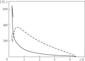
Figure 3. Dimensionless vector potential (solid line) and gamma factor (dashed line) along the trajectory shown in Fig. 2a by a solid curve.
Download figure:
Standard imageTo determine the number of the electrons accelerated to the centre and the values of the longitudinal momenta acquired by the electrons, we calculate the corresponding distribution of the particles, if they were initially uniformly distributed along the  axis. Figure 4 shows the distribution of the particles inside a sphere of radius
  as a function of the longitudinal momentum. One can see that there is a maximum in the vicinity of the highest attainable longitudinal momenta that are about 2.3 times higher than the corresponding values of the vector potential, i.e.,
  at
at  and
and  at
at  . This maximum in the distribution is due to the large time of the interaction of these particles with the wave. Figure 5a shows the dependence of the maximum longitudinal momentum on the power
  , which agrees with the above assessment, and a longitudinal momentum, acquired in a plane wave with the amplitude corresponding to the field amplitude of the dipole wave at a point of the electron trapping (inset in Fig. 5a). These values are, of course, less than those in the plane of the dipole wave, which is associated with an increase in the amplitude of the dipole wave as it approaches the focus and, consequently, with a large longitudinal momentum acquired. However, it should be noted that in the field of the plane wave the maximum longitudinal momentum
  achieved at a distance
  from the point of initial location of the electron, and it is higher than the maximum value
  in the dipole configuration (Fig. 5b). Thus, at a power of
  we have
  and
and  . Since the distance
  , corresponding to the electron trajectories in the field of the dipole wave, is much greater than the distance to the focal point, we can say that the rate of the delay of the electron from the leading edge of the wave is higher in the dipole wave (Fig. 2).
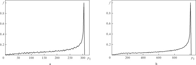
Figure 4. Longitudinal momentum distribution functions of the electrons trapped inside a sphere of radius  as they interact with the dipole wave with a power of (a) 10 and (b)
  and a duration equal to half the period of the field.
Download figure:
Standard image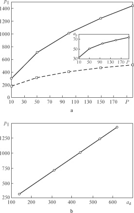
Figure 5. Maximum longitudinal momentum of the electrons trapped inside a sphere of radius  vs. [(a), solid line] the power of the dipole wave with a duration equal to half the period of the field and (b) vs.
  . The dashed curve in panel (a) is the maximum longitudinal momentum of the particle, which moves in the field of the plane wave with an amplitude equal to the field amplitude of the dipole wave at the point of trapping
  (inset), at the observation point as a function of the power of the dipole wave,
  .
.
Download figure:
Standard image3.2. Incident pulses with a smooth envelope
For the analysis of realistic scenarios of interaction we consider the incident pulse with a smooth envelope, which may be important for the electrons accelerated to the centre and able to experience the impact of both the incident wave and the wave passed through the centre. First, consider the distribution of electrons over the longitudinal momenta, similar to that shown in Fig. 4. Figure 6 shows the corresponding distribution for a pulse with the envelope  , including 3 and 10 cycles of the field. For a short pulse (Fig. 6a), together with the maximum achievable longitudinal momentum of the order of the maximum field amplitude, additional peaks appear, which correspond to the local maximum in the distribution of the instantaneous pulse intensity. Interesting enough is the fact that for long pulses (Fig. 6b) high-energy peaks are suppressed due to the interaction of electrons with the counter (passed through the centre) wave, which can dramatically reduce the longitudinal momentum due to radiation reaction, as well as complicate the structure of the distribution function due to electron scattering by the counterpropagating wave.
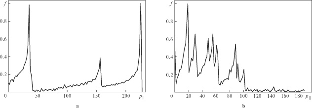
Figure 6. Longitudinal momentum distribution functions of the electrons trapped inside a sphere of radius  as they interact with the dipole wave with a total duration of (a) 3 and (b) 10 periods of the field and a power of
  .
.
Download figure:
Standard imageFor more detailed analysis we consider the trajectories of the electrons trapped at the periphery and accelerated toward the centre. Figure 7 shows the trajectories of the electrons moving in the field at two different pulse durations and a power of  both including and neglecting the radiation reaction. Each vertex of the trajectories corresponds to the electron delay in the reference frame of the incident wave by
  . One can see that in the field of the plane wave the delay occurs later than in the field of the dipole wave; in addition, in the field of the dipole wave the electron moves along a loop trajectory, which is qualitatively different from the case of the plane wave trajectory. In the field of the plane wave the loop motion is possible when the electron initially moves towards the laser pulse. This fact reduces the maximum attainable Lorentz factor of the accelerated electrons by
  times, where
  and
and  are initial values of the gamma factor and the electron velocity. The loop motion in the dipole wave, corresponding to the motion towards the pulse, can be seen in the electron trajectory, shown in Fig. 7b and in Fig. 7d, which shows the function
  (
( is the angle between the electron velocity vector and electron direction to the centre of the dipole wave). One can see that the angle
  in the case of loop motion may be higher than
  and even up to
  .
.

Figure 7. Trajectories of electrons interacting with the dipole wave of duration (a) 3 and (b) 10 periods of the field and a power of  with (1) and without (2) radiation reaction taken into account. Trajectory (3) in panel (b) corresponds to the motion of an electron in the field of the plane wave at the corresponding amplitude (inset in Fig. 5a) with radiation reaction taken into account [the insets show enlarged peaks of trajectories (1) and (3)]; panel (b) shows the field distribution of the dipole wave (superposition of the converging and diverging waves) with a power of
  and a duration of 10 periods of the field near the focus as a function of the longitudinal coordinate [the trajectory of the electron oscillating in the region of the maximum of the field is shown in panel (b) by curve (1)]; panel (d) shows the cosine of the angle between the velocity vector of the electron and the direction from the electron to the centre of the dipole wave corresponding to the initial part of the trajectory in panel (b) [curve (1)].
Download figure:
Standard imageThus, the dipole wave due to the phase front curvature turns the particle and makes it move towards the wave. By analogy with the interaction of an electron with a plane wave, which initially moves towards a wave with the same gamma factor, we can conclude that the effect of the front curvature slows down the acceleration. An important feature of the trajectories shown in Fig. 7 is also their qualitative dependence on the radiation reaction force. As noted above, it can be ignored as long as the particle interacts predominantly with the copropagating wave (corresponding to  in Fig. 7). Then, the particle is accelerated to the centre, begins to interact with the counterpropagating wave, and the role of the radiation reaction increases significantly; thus, according to (1), the regime of this interaction may become radiation-dominated. For the parameters, corresponding to trajectory (1) in Fig. 7b,
  , where
  is the gamma factor of the particles at the initial moment of interaction with the counterpropagating wave
  . One can see that the radiation reaction can confine the particle in the region of the strong field, while without taking it into account the particle quickly leaves the focal region. From a comparison of the trajectories in Fig. 7b and the field distribution in Fig. 7c one can see that a trajectory can be realised when the electron oscillates around a local maximum of the field for a long time (for a few oscillations of the field) before the ponderomotive force expels it in the transverse direction.
3.3. Characteristic features of the electron radiation
Characteristic features of the electron emission for two pulse durations can be easily obtained through a comparative analysis of the spectral output powers in different parts of the trajectories. For a short pulse the trajectory of motion (1) in Fig. 7a clearly shows that the qualitative change in the radiation behaviour stems from the collision of an electron with the wave passing through the centre (solid curve in Fig. 8a); in this case, the emission occurs mainly in the region  , and its power greatly increases compared to the power at the initial points of the trajectory (in particular, at point
  shown by the dashed line). Note that the radiation in the region
  occurs at much higher frequencies, which actually corresponds to the emission of a relativistic electron in a counterpropagating wave. In the case of a long pulse the main contribution to the radiation whose spectrum is shown in Fig. 8b, is made by the electrons oscillating in the region of the strong total field of the incident wave and the wave passed through the centre with the gamma-factor corresponding to the local value of the vector potential. The typical trajectory of the electron in the field of the long pulse is shown in Fig. 7b, from which it can be clearly seen that before reaching the centre the electron initially accelerated by the field of the incident wave is sitting in the antinodes of the field at a distance of
  from the centre. In this phase of the motion its quasi-periodic trajectory corresponds to a purely oscillatory motion of the electron in the field of the standing wave, which is consistent with the relevant characteristics of the radiated power. For comparison, the dashed lines show the spectral powers emitted by the electron at a previous moment of time, corresponding to the acceleration stage, and therefore interaction only with a copropagating wave, i.e., when it is at point
  . These curves are an indicative of a much smaller radiative power of the electron before they start interacting with the counterpropagating wave. We also note that the spectral powers represented by the solid curves in Fig. 8 are almost identical, and this, despite the different nature of radiation, is due to the fact that the characteristic values of the longitudinal and transverse momenta in both cases have the same order and are determined by the local values of the vector potential.
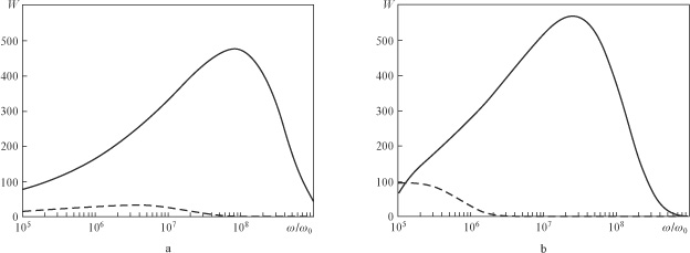
Figure 8. Power emission spectra of an electron in the field of the dipole wave with a duration of (a) 3 and (b) 10 periods of the field and a power of  . The solid curve in panel (a) corresponds to an instant of time
  from the beginning of the interaction with the counterpropagating wave
  , and in panel (b) – a characteristic power emission spectrum of an electron oscillating near the field maximum; dashed lines show a characteristic spectrum before the interaction with the counterpropagating wave.
Download figure:
Standard image4. Conclusions
We have analysed the ultrarelativistic motion of the electron and the characteristics of their radiation in the field of two waves: a plane linearly polarised wave and a converging dipole wave.
In the case of a plane wave we have derived the expressions for the radiation characteristics of the accelerated electrons (total power, power emitted per unit solid angle, and characteristic frequency), and have shown that the account for the radiation reaction force can qualitatively change the character of the motion and characteristics of radiation, respectively.
Analysis of the electron motion in the field of the converging dipole wave shows that it depends strongly on the pulse shape and is determined to a large extent by the front curvature. In particular, for pulses with a sharp switching on of the field, the maximum attainable (in the acceleration) longitudinal momenta are close to the values of the vector potential  at the point of the particle location, which is much smaller than the corresponding values
  in the field of the plane wave. We have determined the distribution function of the electrons accelerated to the centre due to the longitudinal momentum, the function being maximal in the region of the maximum achievable pulses because of the long times of interaction between electrons with the pulses and the wave. For relatively long pulses with a smooth switching on of the field it is shown that the main contribution to the emission is made by electrons oscillating in the central region near the field maximum, the relativistic factor of which is approximately equal to the vector potential. The formation of such trajectories is due to the transition of the particle – field interaction to the radiation-dominated regime.
Acknowledgements
The work was supported by the programme 'Extreme Light Fields and Their Applications' of the Presidium of RAS.