
ABSTRACT
We discuss the polarization properties and first‐order diffraction efficiencies of volume phase holographic (VPH) transmission gratings, which can be exploited to improve the throughput of modern spectrographs. The wavelength of peak efficiency can be tuned by adjustment of the incidence angle. We show that the variation of the Kogelnik efficiency versus Bragg angle depends only on one parameter, given by Ptune = (Δnd)/(nΛ), where Δn is semiamplitude of the refractive index modulation, n is the average index, d is the thickness of the active layer, and Λ is the grating period. The efficiency has a well‐defined dependence on polarization. In particular, it is possible to obtain theoretical 100% diffraction efficiency with one linear polarization at any angle, or to obtain 100% efficiency with unpolarized light at specific angles. In the latter case, high efficiency is the result of aligning the peaks of the s‐ and p‐polarization efficiency‐versus‐thickness curves. The first of these "s‐p–phased gratings" for astronomy is in use with the 6dF spectrograph. Consideration of polarization is particularly important for high spectral resolution, which requires large incidence angles. We also discuss the possibility of separating polarization states for improved throughput along the entire optical train of a spectrograph.
Export citation and abstract BibTeX RIS
1. INTRODUCTION
Astronomical spectrographs have undergone a major revolution during the past few decades (van Breugel & Bland‐Hawthorn 2000; Iye & Moorwood 2000, 2003; Larar & Mlynczak 2002; Atad‐Ettedgui & D'Odorico 2003). The revolution has concentrated on the multiplex advantage in order to allow large numbers of objects or contiguous spatial elements to be observed simultaneously. This is possible because large detectors are now available, which can also lead to wide‐angle fields and/or wide spectral coverage.
Even though modern spectrographs can achieve up to 40% throughput (optics+disperser+detector), instrumental throughput remains a key issue for spectrograph design. Moreover, some fraction of the light lost along the optical train is received as stray light at the detector and usually provides a major source of systematic error in the detected signal.
Now that detectors are widely available with 90% quantum efficiency in the visible wavelength region, the remaining gains must come from more efficient designs of the optics and dispersing element or elements, which we discuss. We concentrate specifically on volume phase holographic (VPH) gratings used in transmission (Arns 1995). However, we note that similar consideration could apply to a much wider class of dispersing elements (e.g., reflection gratings, prisms).
What has not been discussed widely is the advantages of the polarization properties of VPH gratings; in particular, achieving the ideal of 100% throughput at any diffraction angle in one linear polarization. In addition, a theoretical diffraction efficiency of 100%, in both polarizations, can be achieved at specific angles with particular instrument configurations. An instrument that exploits the advantages of VPH gratings can, in principle, greatly reduce systematic error in the detected signal.
VPH gratings are already in use or are being brought into use in a number of spectrographs, including: LDSS++ and Taurus at the Anglo‐Australian Telescope (Glazebrook et al. 1998); OSIRIS at the Gran Telescopio Canarias (Cepa et al. 2000); the Goodman spectrograph at the SOAR Telescope (Clemens et al. 2000); M2HES at the Magellan II Telescope (Bernstein et al. 2002); FORS at the Very Large Telescope (Monnet et al. 2002); FOCAS at the Subaru Telescope (Ebizuka et al. 2003); and LRS at the Hobby‐Eberly Telescope (Hill et al. 2003). The potential of VPH gratings for astronomical applications has been investigated and discussed by Barden and others (Barden et al. 1998, 2000a, 2000b, 2002, 2003; Robertson et al. 2000; Rallison et al. 2003; Tamura et al. 2004). Here we elucidate the physics of VPH gratings with emphasis on their polarization and tuning properties, and we discuss how these properties might be exploited to improve the performance of spectrographs. In § 2 we describe the physics of VPH transmission gratings, in § 3 we describe some applications taking advantage of the well‐defined polarization properties, in § 4 we summarize, and in the Appendix we give equations for calculating the resolving powers of transmission gratings immersed between prisms.
2. VPH GRATING PHYSICS
In a VPH transmission grating, light is diffracted as it passes through a thin layer (3–30 μm) of, typically, "dichromated gelatin" (DCG; Shankoff 1968; Meyerhofer 1977; Rallison 1992) in which the refractive index is modulated approximately sinusoidally. The modulations are produced by the interference of two large collimated laser beams, and subsequent processing. These gratings offer a number of advantages over other gratings, including the following:
- 1.Diffraction efficiencies can approach 100% near the design wavelength.
- 2.The wavelength of peak efficiency can be tuned by adjustment of the incidence angle.
- 3.The line density can be significantly higher (up to 6000 lines mm−1) than the maximum generally available for ruled gratings, which is about 1200 lines mm−1.
- 4.Transmission gratings allow shorter pupil relief between the grating and both the collimator and camera, which can reduce the required camera aperture, increase the field of view, and/or improve the point‐spread function (PSF).
- 5.The grating is sandwiched between glass substrates, providing a robust device that can be easily cleaned and have antireflection (AR) coatings applied.
- 6.Large grating sizes are feasible.
Further advantages and disadvantages are described by Barden et al. (2000a). In this paper we also consider the ability to optimize the efficiency for a particular polarization state.
2.1. Diffraction by a VPH Grating
Light passing through a VPH grating obeys the usual grating equation, given by

where m is an integer (the spectral order), λ is the wavelength in vacuum, ni is the refractive index of the medium, Λg is the grating period (which is the projected separation between the fringes in the plane of the grating, equivalent to the groove spacing on a ruled grating), αi is the angle of incidence, and βi is the angle of diffraction from the grating normal (the sign convention is such that βi = -αi means no diffraction; i.e., zeroth order). Note that the grating equation can apply to angles in the DCG layer (i = 2), in the glass substrates (i = 1), or in the air (i = 0) as long as the air‐glass boundaries are parallel to the DCG layer (see the Appendix for the general case). Figure 1 shows a diagram of a VPH grating with the appropriate angles and lengths defined.
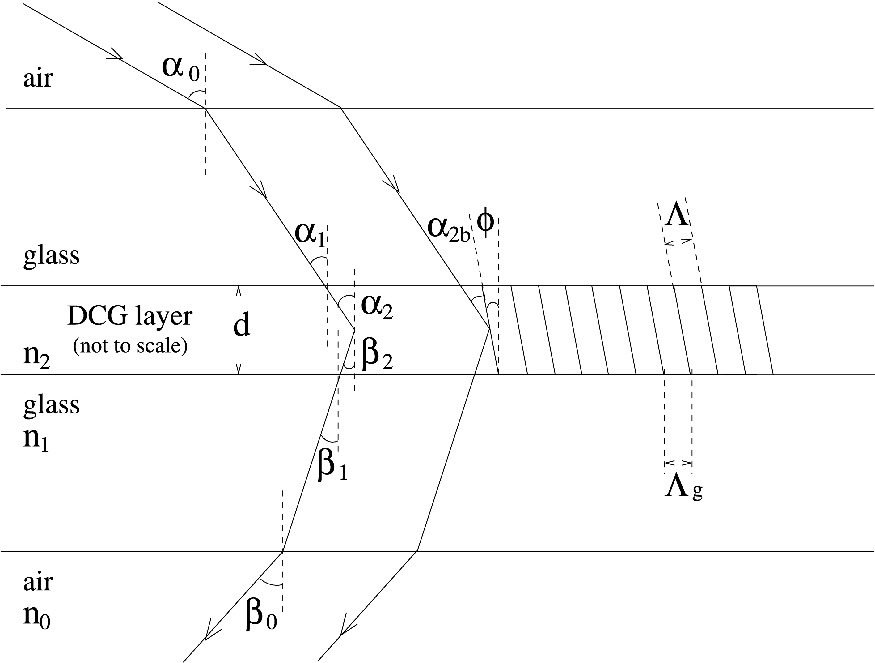
Fig. 1.— Diagram of a VPH grating. The equally spaced lines in the DCG layer represent the peaks of a modulated refractive index (n2 is the average value). Typically, n2 is in the range 1.2–1.5, depending on the DCG processing (Rallison & Schicker 1992), n1≃1.5, and n0 = 1. For unslanted fringes, ϕ = 0°, Λ = Λg, and α2b = α2.
For the simplest VPH transmission grating, the plane of the fringes is perpendicular to the plane of the grating (we use the term "unslanted fringes"). In this case, Λg is the same as the separation between the fringes Λ. For the general case,

where φ is the "slant" angle between the grating normal and the plane of the fringes.
2.2. The Bragg Condition
In a VPH grating, high diffraction efficiency can occur when the light is effectively "reflected" from the plane of the fringes; i.e.,

where α2 is the angle of incidence and β2 is the angle of diffraction from the grating normal in the DCG layer. The phenomenon is analogous to Bragg "reflection" of X‐rays from the atomic layers within a crystal lattice. In both cases the thickness of the medium being ≫λ can result in constructive interference of scattered radiation in that direction. The essential role of the nonzero thickness of the DCG layer is responsible for the term "volume" in VPH gratings. This "reflection," combined with the grating equation, gives the well known "Bragg condition," which can be written as

where n2 is the refractive index of the DCG layer, and α2b is the angle of incidence with respect to the plane of the fringes; i.e., α2b = α2 - ϕ. Under this condition, α2b is called the "Bragg angle." Light nearly obeying this condition is still diffracted according to the grating equation (eq. [1]), but usually with lower efficiency. At wavelengths or angles sufficiently outside the Bragg condition, light passes through the grating without being diffracted. The Bragg angle is an important parameter for diffraction by VPH gratings. It directly affects efficiency and bandwidth (§§ 2.3–2.5), and indirectly affects resolving power (Appendix).
We note that unslanted fringes may be preferred, because with slanted fringes, the tilt may change or the fringes may curve during DCG processing (Rallison & Schicker 1992). For unslanted fringes (ϕ = 0, Λ = Λg, n2 sin α2b = ni sin αi), the Bragg condition can also be written as

This defines the Bragg wavelength for a given order of diffraction m, and corresponds to Littrow diffraction because βi = αi.
2.3. First‐Order Diffraction Efficiencies
The Bragg condition is not the only condition for high efficiency. The diffraction efficiency depends on the semiamplitude of the refractive‐index modulation (Δn2) and the grating thickness (d) in addition to the incidence and diffracted angles. Kogelnik (1969) determined first‐order diffraction efficiencies at the Bragg condition, using an approximation that is accurate (to within 1%) when

where ρlimit ≈ 10. Substituting λ = 2n2Λsin α2b (eq. [4] with m = 1) and rearranging gives

Thus, for a given refractive‐index modulation, Kogelnik's theory is accurate for Bragg angles above a certain value. For unpolarized light, the Kogelnik efficiency is given by

where the first term is for s‐polarized light (the electric vector is perpendicular to the fringes), and the second term is for p‐polarized light (the electric vector is parallel to the fringes).4
Figure 2 shows the variation of efficiency versus grating thickness for two different Bragg angles (with fixed Δn2 = 0.07 and λ = 0.6 μm). The efficiencies were determined using GSOLVER,5 which provides a numerical calculation using rigorous coupled‐wave analysis (RCWA; Magnusson & Gaylord 1978; Moharam & Gaylord 1981, 1983; Gaylord & Moharam 1985). In these cases, the numerical results are in excellent agreement with Kogelnik's theory (eq. [8]), because equation (6) is satisfied. Note that no surface losses were included. In the upper plot, the first peaks of the s‐ and p‐polarizations are close together, and a diffraction efficiency of about 90% in unpolarized light can be achieved (with a thickness of 5 μm). In the lower plot, the 35  3 Bragg angle is a special case in which the second peak of s‐polarization matches the first peak of the p‐polarization, and near 100% efficiency can be achieved (with a thickness of about 10 μm). This special "s‐p–phased grating," also called a "Dickson grating," was noted by Dickson et al. (1994).
If we consider only the s‐polarization curve in the upper plot of Figure 2 (dashed line), notice that theoretical 100% efficiency occurs with a thickness of 4 μm. If the thickness is doubled to 8 μm, the efficiency falls to zero. This is not surprising, since if it took 4 μm of refractive‐index‐modulated medium to coherently diffract the light, then twice as much medium causes destructive interference in the first‐order diffraction direction (and the light will instead pass through without diffraction). At 12 μm, the s‐polarized light is returned to 100% diffraction efficiency. Generally, p‐polarized light is characterized by a reduced coupling with the medium, which means that larger thicknesses are required to coherently diffract the light, depending on the Bragg angle (the cos [2α2b] factor in eq. [8]).
The differences in efficiency between the two polarization states can be used to produce polarization‐selective devices (Kostuk et al. 1990; Dickson et al. 1994; Huang 1994). In addition, the polarization properties can be used to determine the average refractive index of the DCG after processing (Rallison & Schicker 1992; Dickson et al. 1994). With this technique, measurements of the average index of highly processed DCG (Δn2>0.1) give low values of n2 ≈ 1.25.6 Unprocessed DCG has an index of 1.54. The average index is important, since it determines the air angles (α0) for the special angle gratings; for example, the 35° Bragg angle s‐p–phased grating utilizes incidence angles of 46°–48° in air (Rallison et al. 2003).
2.4. Tuning a VPH Grating
A VPH grating can be tuned by changing the incidence angle, which changes the Bragg condition, to optimize the diffraction efficiency for a desired wavelength. For example, consider a VPH grating with 1315 lines mm−1 (Λ = 0.76 μm, n2 = 1.5) at α2b = 16°. The first‐order Bragg condition gives λ = 0.63 μm, whereas at α2b = 20°, the Bragg condition gives λ = 0.78 μm. The Bragg wavelength is generally close to, but not necessarily the same as, the blaze wavelength, which refers to the wavelength of peak efficiency for a given incidence angle. Note that the blaze wavelength does not depend strongly on the shape of the index modulations, which are presumed to be sinusoidal in the models. To detect the blaze wavelength, it may be necessary to change the grating‐to‐camera angle, as well as the collimator‐to‐grating angle (see Bernstein et al. 2002 for an alternative approach using a pair of mirrors). A VPH grating works best at one incidence angle and one wavelength (the maximal peak), and even though the blaze wavelength can be changed by varying the tilt, the peak efficiency is lower away from the maximal peak. The maximal peak is determined by the grating thickness and the refractive‐index modulation, as well as the grating period and spectral order (§ 2.3).
To illuminate how the Bragg‐condition diffraction efficiency varies, we can rearrange the equation for the Kogelnik efficiency in the following way. Substituting for λ (from eq. [4]) in equation (8) (and using a trigonometric identity, 2sin αcos α = sin 2α), we derive

where

Thus, this "tuning parameter," which depends only on the properties of the DCG layer, determines how the efficiency of a VPH grating varies with Bragg angle. In other words, all gratings with the same value of Ptune have the same tunability and the same peak efficiency (subject to eq. [6]), while n2Λ sets the relationship between λ and α2b (§ 2.2), and Δn2 and d can be adjusted, within a certain range, to set the bandwidth (§ 2.5).
Figure 3 shows the variation of diffraction efficiency versus Bragg angle, with unpolarized light, for: (1) fixed gratings, with various values of Ptune, determined using Kogelnik's theory (represented by the lines); and (2) maximum designable efficiencies, with fixed wavelength and DCG modulation, determined using RCWA (represented by the symbols). The asterisks represent standard grating designs, while the squares and triangles represent s‐p–phased grating designs. These efficiencies were determined, using RCWA, by varying d with fixed Δn2.7

Fig. 3.— First‐order diffraction efficiencies versus Bragg angle with unpolarized incident light. The lines represent efficiencies at the Bragg condition determined using Kogelnik's theory for seven gratings with Ptune values of 0.1–0.5, 1.4, and 2.5 (fixed intrinsic grating parameters; see eqs. [9] and [10]). The symbols represent maximum designable efficiencies determined using RCWA (varying d, Λ; fixed λ = 0.6 μm, Δn2 = 0.07, n2 = 1.5). The asterisks represent standard gratings, in which the optimum thickness with unpolarized light is near the first peak of the s‐polarization curve (e.g., upper plot of Fig. 2, Ptune≲0.5). The squares and triangles represent s‐p–phased gratings in which the thicknesses are near the second peak and third peak, respectively, of the s‐polarization curve (e.g., lower plot of Fig. 2, Ptune ≈ 1.4; Ptune ≈ 2.45). The efficiencies from the RCWA calculations drop at low angles, because Kogelnik's approximation is no longer accurate below about 20°, with Δn2/n2 ≈ 0.05 (eq. [7]). Note that the grating period, wavelength, and Bragg angle are related by eq. (4).
At angles below ∼15°, the efficiencies determined using RCWA fall below that of the maximum efficiencies of curves with Ptune values of 0.1–0.2. This is because Kogelnik's approximation is no longer accurate below about 20°, with Δn2/n2 ≈ 0.05 (eq. [7]). Low‐angle efficiency can be increased by lowering Δn2 (and raising d). At angles between 15° and 30°, the maximum efficiencies of curves with Ptune values of 0.3–0.5 closely follow the asterisks showing that Kogelnik's theory agrees with the RCWA calculations. This agreement also applies to higher angles. Around the angles of 35° and 55°, the designs can make use of special s‐p–phased gratings that have Ptune values of 1.3–1.5 (Fig. 3, squares). Around the angles of 39° and 51°, the designs can make use of s‐p–phased gratings that have Ptune values of 2.4–2.5 (triangles). Note that at 45°, a maximum efficiency of only 50% can be achieved because of the loss of p‐polarization (eq. [8]). To utilize higher Bragg angles, very high air‐to‐glass incidence angles are required (>60°, with n2 ≈ 1.25), or prisms need to be attached to the grating.
The lines in Figure 3 represent efficiencies derived by "tuning" various gratings that are optimized for unpolarized light at a particular angle. At angles between 25° and 32°, it is still possible to obtain high efficiency (>90%), but with only one linear polarization state. Note that the ability of a VPH grating to be tuned in blaze wavelength (by changing the grating tilt) also results in multislit spectrographs using VPH gratings exhibiting a shift of the blaze wavelength for objects that are off‐axis in the spectral direction (Robertson et al. 2000). Figure 4 shows diffraction efficiency versus wavelength for a VPH grating with 1315 lines mm−1, tuned to three different blaze wavelengths. As the grating tilt is changed, the peak efficiency drops slightly as the blaze wavelength moves away from the maximal peak.

Fig. 4.— Tuning a VPH grating. First‐order diffraction efficiencies versus wavelength are shown for three different incidence angles. The efficiencies were determined using RCWA with Δn2 = 0.07, n2 = 1.5, unslanted fringes, and unpolarized light. The Bragg angles are shown at the Bragg wavelengths, which are marked by short vertical lines. Note that the blaze wavelength (the peak of each efficiency curve) is slightly different from the Bragg wavelength for the low‐ and high‐incidence angles.
2.5. Bandwidth of Efficiency versus Wavelength
How does the efficiency decrease away from the Bragg wavelength? Kogelnik determined an approximate formula for the full width at half‐maximum (FWHM) of the efficiency bandwidth (Δλeff) in first order, which is given by

We can see immediately that for a given resolution and wavelength (Bragg angle α2b and grating period Λ fixed), increasing the thickness decreases the bandwidth. Figure 5 shows efficiency versus wavelength for four different thicknesses. The efficiencies were determined using RCWA.

Fig. 5.— Variation of the diffraction efficiency versus wavelength for four different grating thicknesses. The efficiencies were determined using RCWA. All the gratings have 1710 lines mm−1 unslanted fringes with light incident at α2b = 20° (the first‐order Bragg angle for λ = 0.6 μm and Λ = 0.585 μm). Here Δn2 is 0.02, 0.04, 0.07, and 0.10 for each grating, from the thickest to the thinnest, respectively.
To maximize the bandwidth, Δn2 should be as large as possible as long as the gratings can be manufactured sufficiently thin (remembering that Δn2d determines the maximal peak). However, the efficiency decreases significantly if Δn2 is increased such that ρ becomes much less than 10 (eq. [6]). The lost power from first‐order diffraction is approximately 1/ρ2 (Rallison et al. 2003). Therefore, to maximize the average efficiency across a desired wavelength range, there may be a trade‐off between maximizing the bandwidth and maximizing the peak efficiency. For Bragg angles greater than 20°, this is generally not an issue, because the upper limit on Δn2 is set by the manufacturing process. Values of Δn2 of up to 0.10–0.15 can be achieved using DCG (Dickson et al. 1994).
2.6. Other Issues
So far we have dealt mainly with theoretical results either from Kogelnik's equations or from RCWA numerical calculations. A number of other points that could also affect efficiency are described briefly below.
- 1.Transmission losses.—The main losses will generally be from the air‐glass boundaries. Figure 6 shows transmission efficiency versus incidence angle at a boundary. With n0 = 1, n1≃1.5, and no AR coatings, the combined losses will be about 8%–10% for incidence angles (α0) from 0°–45° with unpolarized light. These can be reduced with AR coatings applied to both surfaces. For wavelengths between 0.4 and 2 μm, the transmittance of a thin layer (5 μm) of DCG is very high, and losses are insignificant (Barden et al. 1998). Between 0.3 and 0.4 μm, losses could be a few percent.
- 2.The refractive index of the DCG layer.—The average index (n2) and the semiamplitude of the modulations (Δn2) will not be exactly constant. A small variation with wavelength is not expected to have a significant impact on the performance of a VPH grating. Of possible importance is a variation of the index modulation as function of depth or position across the surface. In the first case, a reduction with depth means that the effective thickness is less than the thickness of the DCG layer, and in the second case the diffraction efficiency will vary with position unless there is a high degree of uniformity in the laser beams that produce the modulation (Rallison et al. 2003). An additional issue concerning the difference between nonsinusoidal and sinusoidal refractive‐index modulations is discussed by Barden et al. (2000a). This can improve diffraction efficiency in second and higher orders.
- 3.Defects and errors in manufacturing.—Defects could include deviations from parallelism between fringes and other nonuniformities across the grating. Errors are deviations of VPH specifications from those requested. This may not be important, since the grating can be tuned to the required wavelength even if the maximal peak did not meet specifications (e.g., Glazebrook 1998).
See Barden et al. (2000a) for the performance evaluation of three VPH gratings for astronomical spectrographs.

Fig. 6.— Theoretical transmission efficiency at an air‐glass boundary. The solid line represents unpolarized light, while the dashed and dotted lines represent the s‐ and p‐polarization states, respectively. The advantage of p‐polarization for high‐resolution spectrographs is apparent. The formulae and derivations for these curves can be found in optics textbooks (e.g., Hecht 1974).
3. EXAMPLE CASES AND DISCUSSION
3.1. s‐p–phased Gratings
In most spectrographs, the polarization states are not separated, and therefore the efficiency with unpolarized light is important. For low‐resolution spectrographs (α2b≲20°), the theoretical diffraction efficiency can be above 95% with standard VPH gratings. At higher resolution, the efficiency of standard gratings can be significantly lower. Instead, s‐p–phased gratings can be used to obtain higher efficiency at specific angles (§§ 2.3–2.4).
The first s‐p–phased (Dickson) grating for astronomy was manufactured by Ralcon8 for the 6dF multiobject spectrograph at the UK Schmidt Telescope (Saunders et al. 2001). It was specially designed to observe the calcium triplet around 0.85 μm with a resolving power of about 8000 (first order, 1700 lines mm−1). The central wavelength is diffracted with a total beam deviation in air of 94°, which makes use of the 35° special Bragg angle. The theoretical diffraction efficiency is above 95% in the range 0.835–0.865 μm, and the performance is near to that. In addition, the camera and collimator are close to the grating. Figure 7 shows the 6dF spectrograph in this configuration. This has significantly improved the PSF at the detector in comparison with using reflection gratings that have similar resolving powers (W. Saunders 2003, private communication).

Fig. 7.— The 6dF bench‐mounted spectrograph with the 1700 lines mm−1 s‐p–phased grating in place. There is a 90°–100° beam deviation between the last element of the collimator (left) and the camera (right). (Photograph taken by Bob Dean and Will Saunders.)
If we wish to go to a higher spectral resolution but are limited to a certain maximum deviation between collimator and camera beams, then prisms can be attached (Figs. 8–9, Appendix). For example, a grating with 2400 lines mm−1 and 20° prisms (n2 = 1.25, Δn2d = 0.73, n1 = 1.5) that operates at λ = 0.85 μm with a 111° total beam deviation in air (α0 = 355, α1 = 43°) can make use of the 55° special Bragg angle for high efficiency (Ptune = 1.4). This type of grating is challenging to produce because of the difficulty in testing the efficiency prior to attaching prisms (consider total internal reflection), but if high resolution and high efficiency are important over a narrow wavelength range, then it could be useful. Testing is needed to determine the laser exposure levels for the DCG. One solution would be to design the grating to work at the 35° Bragg angle, which has the same Ptune value. This would require testing at a wavelength 0.708 [= sin (35.3)/sin (54.7)] times the design wavelength, subject to variations in n2 and Δn2 with wavelength (eqs. [4] and [10]). Note that in order for such gratings to reduce systematic noise in the detected signal, it may be necessary to use a filter to block scattered light from outside the desired wavelength range.

Fig. 8.— Resolving powers of VPH transmission gratings versus total beam deviation. The top line represents a grating immersed between two 40° prisms (with n1 = 1.5), and the dashed line between two 20° prisms and the lower line represents a grating with no prisms attached. The crosses are set at 10° intervals in Bragg angle (with n2 = 1.3). The resolving powers are normalized to unity for the zero‐deviation 40° prism model. See Fig. 9 for the prism model, and the Appendix for the calculation of resolving power. Note that the dispersion caused by differential refraction is not included.
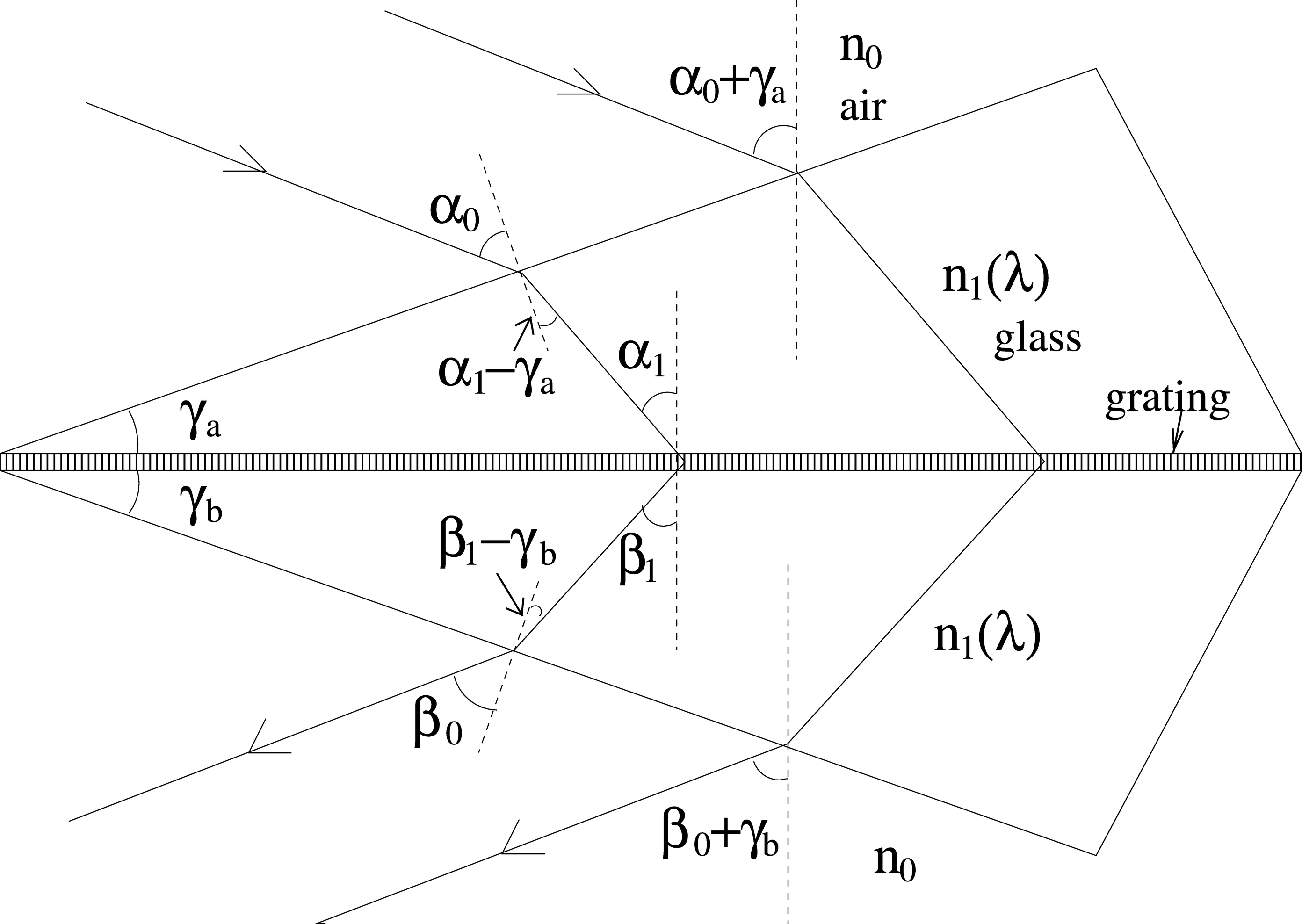
Fig. 9.— Diagram of a prism model for an immersed transmission grating. The dependence of the spectral resolving power on the angles and indices is given in the Appendix. In Littrow configuration, with both prism angles equal to γ, the resolving power is approximately proportional to n1 tan α1 cos (α1 - γ)/cos α0.
3.2. Separating Polarization States in a Spectrograph
If we could envisage an ideal spectrograph, what properties would it have? The primary problems are scattered light at refractive index boundaries, and the difficulties of dispersing s‐ and p‐polarization states without compromise of one or the other. We note that both of these problems arise from the geometry of the wavefront with respect to the optical element/grating.
A substantial increase in efficiency, perhaps approaching the ideal, could be achieved by allowing the two polarization states to be handled separately in a spectrograph. One approach would be to separate the two polarizations at a polarizing beam splitter (Goodrich 1991). They would then propagate along separate paths where all the optics would be oriented to minimize light loss for that polarization. In particular, a VPH grating can be optimized for almost any angle to obtain near 100% efficiency at blaze wavelength in one polarization. An alternative to the use of a beam splitter would be to use a VPH grating itself. The collimated beam would encounter a VPH grating in the normal way, with diffracted light going to a camera. But the grating would be designed so that first‐order diffraction would be optimized for a single linear polarization, while zeroth order would be optimized for the other polarization.9 The undiffracted transmitted beam could then go on to a second VPH grating optimized for the other polarization, feeding into a second camera. Whatever method is used to separate the polarizations, note that it is not necessary to achieve complete separation, and hence the requirement for the polarizing element is less demanding than for a polarimeter. This is because the only effect of mixing in a small amount of light with the "wrong" polarization is that it will be less efficiently processed downstream. But it will still make some positive contribution to the signal, and the decrease in efficiency will be a second‐order effect.
The cases in which separate polarizations would most improve in efficiency is with high spectral resolution. Large beam deviations and large air‐to‐glass incidence angles are needed to obtain the highest resolutions (Fig. 8). At these large angles, the boundary‐transmission efficiency of s‐polarization is low, but the efficiency in p‐polarization remains high (Fig. 6). For example, one could design a grating that operates with light incident near Brewster's angle on the air‐glass boundary and with the DCG layer optimized for p‐polarization efficiency. This would provide a high‐resolution grating with near 100% efficiency in one linear polarization. Naturally, polarimetry measurements could also take advantage of these one‐polarization optimized gratings. Note also that separating polarization states could be used to optimize efficiency for reflection grating spectrographs (Lee & Allington‐Smith 2000) and for background‐limited observations during bright Moon phases (Baldry & Bland‐Hawthorn 2001).
We are moving toward precision measurements in many areas of astrophysics. The major limitation continues to be systematic sources of noise. In order to combat this, many experiments are cast as differential measurements, e.g., alternating observations of source and background in order to beat down the systematic errors. This is a highly effective strategy for dealing with external noise sources and some internal sources (e.g., apparatus instability). However, there are internal sources of noise that continue to haunt most spectrographs today, in particular, scattered light. This "ghost light" is not usually suppressed in differential experiments, because it depends on the distribution of light sources over the field of view. Even with mitigation strategies based on light baffles and optimized AR coatings, there is always residual stray light, not least from the optical/IR detector because of its large refractive index compared to a vacuum. But this situation is slowly improving as detectors and matched coatings approach their theoretical maximum.
The only way to guard against stray light is to consider the role of every element in the optical train very carefully and to orient the optical elements accordingly, particularly the choice of AR coating and orientation of the interface to the incoming wavefront. This is easier to do if the wavefront has been divided into its s‐ and p‐states, and each polarization is considered separately. One only has to consider the AR coatings in each of two arms (one for s‐states and the other for p‐states), which can be optimized for throughput. This is not true for a skew ray in natural light, which would require a birefringent coating in order to optimize throughput in both polarization states.
4. SUMMARY
VPH gratings are used in an increasing number of spectrographs because of their high diffraction efficiency. In this paper, we have outlined the basic physics necessary to design VPH gratings. In particular, we have defined a parameter (Ptune) that determines how the efficiency of a grating varies with Bragg angle, we have described the possibility of creating s‐p–phased gratings that can have 100% efficiency with unpolarized light at specific angles, and we have discussed the importance of considering the separate polarization states. The main points concerning tuning and efficiency are given below.
- 1.The grating period (Λ) and the average refractive index of the DCG layer (n2) determine the wavelength as a function of Bragg angle (eq. [4], with m = 1).
- 2.
- 3.s‐p–phased gratings can be created by aligning the peaks of the s‐ and p‐efficiency curves versus DCG thickness at particular Bragg angles (Fig. 2). For example, a grating with Ptune ≈ 1.4 has high efficiency with unpolarized light at a Bragg angle of 35°. Here the second peak of the s‐curve is aligned with the first peak of the p‐curve.
- 4.
- 5.
We have shown how VPH gratings can be manufactured and exploited to ensure higher transmission and better suppression of stray light. This will necessarily force instrument designers into a smaller parameter space, but we feel that there is sufficient freedom within that space to account for most design issues. In any event, we deem these considerations to be paramount if systematic sources of noise are ever to be effectively removed from the apparatus.
We would like to thank Sam Barden, Chris Clemens, Richard Rallison, Will Saunders, and Keith Taylor for information and helpful discussions; and we thank the referee for comments, which have improved the paper. Some of this research was funded by a design study for OSIRIS at the Gran Telescopio Canarias.
APPENDIX A: RESOLVING POWERS OF IMMERSED TRANSMISSION GRATINGS
VPH gratings can be sandwiched between glass prisms. This reduces the total beam deviation and reduces the air‐to‐glass incidence angle (α0), for a given grating and wavelength. This can be useful because the total beam deviation is limited by the physical sizes of the camera and collimator, and because higher incidence angles on air‐glass boundaries give higher reflection losses (for unpolarized light). Here we give the equations for calculating the resolving power of a transmission grating immersed between two prisms.
Figure 9 shows the prism model that we are using with the appropriate angles defined. Light passing through the prism and the immersed grating, with a total beam deviation of α0 + β0 + γa + γb, obeys the following equations:

The resolution can be determined by solving

Here the output angle is regarded as a function of the input angle and the wavelength. This expression represents the condition that incrementing the wavelength by Δλ shifts the output image by the same amount as does the change in the incidence angle across the slit width. The angular size of the slit in the collimated beam, Δα, is given by

where θ s is the angular size of the slit on the sky, and ftel and fcoll are the effective focal lengths of the telescope and collimator, respectively. If n1 and n0 are independent of wavelength (i.e., ignoring differential refraction), then equation (A4) can be solved analytically to give a resolving power of

Note that with γa = γb = 0, this reduces to the well‐known equation for the resolution of an unimmersed grating:

To include the dispersive effects of glass (n1 varying with λ), equation (A4) can be solved numerically. Differential refraction marginally increases the resolving power for typical VPH grism designs.
In Littrow configuration, γa = γb(= γ) and αi = βi, with a total beam deviation of 2α0 + 2γ, the resolving power (n0 and n1 constant) is given by

The usefulness of the Littrow configuration is threefold: (1) VPH unslanted fringes can be used (slanted fringes may curve during DCG processing); (2) the beam size remains about the same, which keeps the camera optics smaller and simpler; and (3) the angular size of the slit remains nearly the same. With unslanted fringes, the important Bragg angle is given by n2 sin α2b = n1 sin α1. Figure 8 shows resolving powers at Littrow versus total beam deviation with the Bragg angle annotated. Note that for a given grating (fixed diffraction order, wavelength, and lines mm−1), prisms typically reduce resolving power, but for a given total beam deviation, prisms typically increase resolving power (Wynne 1991; Lee & Allington‐Smith 2000).
Footnotes
- 4
Note that in some papers the equation for p‐polarization efficiency is incorrectly quoted. The additional coupling parameter, the cosine of the sum of the two angles (cos [2α2b] in this paper), should be placed within the sin 2 brackets. This can make a significant difference. If the coupling parameter is placed outside the brackets, it implies that the efficiency in p‐polarization is always less than in s‐polarization, whereas eq. [8] does not. Instead, the thickness of the grating must be larger to produce the same efficiency in p‐polarization. This is demonstrated in Fig. 2 and is confirmed by coupled‐wave analysis. Note also that we only consider first‐order diffraction in this paper, because VPH gratings generally have significantly lower efficiencies in higher orders.
- 5
The GSOLVER ver. 4.0 diffraction grating analysis tool is developed by Grating Solver Development Company (P.O. Box 353, Allen, TX 75013), available at http://www.gsolver.com .
- 6
Low values of the average refractive index n2 imply that voids are formed in the DCG layer during processing (Curran & Shankoff 1970; Meyerhofer 1977). The exact mechanism is uncertain, and the lowest achievable index depends on the processing technique. In addition, the index derived using the polarization properties, and assuming Kogelnik's theory, may be lower than the "true index" if birefringence is induced in the material (Tholl 1995). However, for VPH design purposes, it is in any case more appropriate to use the "Kogelnik index," which can be regarded as the effective index, determined by Rallison and others, that is needed to satisfy the polarization properties of Kogelnik's theory. Note also that d and Δn2 in the equations of this paper should be regarded as representing the effective thickness and effective index modulation.
- 7
The optimization excluded thicknesses significantly beyond the first peak of the p‐polarization curve. With arbitrarily large thicknesses, it is theoretically possible to obtain 100% diffraction efficiency at any angle (except 45°) with unpolarized light using s‐p–phased gratings (e.g., matching the third peak of the s‐curve with the second peak of the p‐curve). We do not consider these other s‐p–phased gratings, because increasing the thickness has the disadvantage of reducing the efficiency bandwidth (§ 2.5).
- 8
Ralcon Development Lab, P.O. Box 142, Paradise, Utah 84328 (http://www.xmission.com/~ralcon), founded by R. D. Rallison.
- 9