

Abstract
Progress in the definition of the requirements for edge localized mode (ELM) control and the application of ELM control methods both for high fusion performance DT operation and non-active low-current operation in ITER is described. Evaluation of the power fluxes for low plasma current H-modes in ITER shows that uncontrolled ELMs will not lead to damage to the tungsten (W) divertor target, unlike for high-current H-modes in which divertor damage by uncontrolled ELMs is expected. Despite the lack of divertor damage at lower currents, ELM control is found to be required in ITER under these conditions to prevent an excessive contamination of the plasma by W, which could eventually lead to an increased disruptivity. Modelling with the non-linear MHD code JOREK of the physics processes determining the flow of energy from the confined plasma onto the plasma-facing components during ELMs at the ITER scale shows that the relative contribution of conductive and convective losses is intrinsically linked to the magnitude of the ELM energy loss. Modelling of the triggering of ELMs by pellet injection for DIII-D and ITER has identified the minimum pellet size required to trigger ELMs and, from this, the required fuel throughput for the application of this technique to ITER is evaluated and shown to be compatible with the installed fuelling and tritium re-processing capabilities in ITER. The evaluation of the capabilities of the ELM control coil system in ITER for ELM suppression is carried out (in the vacuum approximation) and found to have a factor of ∼2 margin in terms of coil current to achieve its design criterion, although such a margin could be substantially reduced when plasma shielding effects are taken into account. The consequences for the spatial distribution of the power fluxes at the divertor of ELM control by three-dimensional (3D) fields are evaluated and found to lead to substantial toroidal asymmetries in zones of the divertor target away from the separatrix. Therefore, specifications for the rotation of the 3D perturbation applied for ELM control in order to avoid excessive localized erosion of the ITER divertor target are derived. It is shown that a rotation frequency in excess of 1 Hz for the whole toroidally asymmetric divertor power flux pattern is required (corresponding to n Hz frequency in the variation of currents in the coils, where n is the toroidal symmetry of the perturbation applied) in order to avoid unacceptable thermal cycling of the divertor target for the highest power fluxes and worst toroidal power flux asymmetries expected. The possible use of the in-vessel vertical stability coils for ELM control as a back-up to the main ELM control systems in ITER is described and the feasibility of its application to control ELMs in low plasma current H-modes, foreseen for initial ITER operation, is evaluated and found to be viable for plasma currents up to 5–10 MA depending on modelling assumptions.
Export citation and abstract BibTeX RIS
1. Introduction
High fusion performance DT operation (inductive, hybrid and steady-state) in ITER is based on the achievement of the H-mode confinement regime with H98 ⩾ 1 and an edge transport barrier that is expected to lead to the quasi-periodic triggering of edge localized modes (ELMs). Operation of ITER with H-mode plasmas is also foreseen during the non-active (H and He) and DD operation allowing the development of ELM control schemes before DT operation [1]. Naturally occurring (or 'uncontrolled') ELMs in ITER are expected to lead to large power fluxes to plasma-facing components (PFCs) which can decrease their lifetime significantly [2]. ELM control requirements in ITER have recently received focused attention in relation with the proposal to start ITER operation with a W divertor, which was originally foreseen for the beginning of nuclear operations (DD and DT plasmas) and is now being considered also for the start of ITER operation in the non-nuclear phase (H and He plasmas) [1].
This paper describes progress in the evaluation of ELM control requirements for the ITER scenarios from the non-active phase of operations to DT burning plasmas beyond the status described in [3, 4] as well as in the evaluation of the application of the ELM control schemes foreseen in ITER. First, we summarize in this introduction the key assumptions leading to the ITER ELM control requirements described in [3, 4] and we then proceed to describe the progress in their refinement in view of the additional requirements associated with operation with a W divertor in ITER and to the progress in the evaluation of the application of the ELM control schemes in ITER.
In order to ensure an appropriate lifetime of ITER PFCs, guidelines for the maximum power fluxes on these components have been set to avoid localized melting of metallic components or excessive erosion of carbon fibre composite (CFC) components. This maximum power limit corresponds to 50% of the energy density required to melt or to drive excessive erosion of the front face of these components, which are in direct contact with the plasma in stationary phases. This allows for some margin for erosion of CFC or melting of the PFCs' front faces which is sufficient to also avoid large-scale melting of the edges of the individual macro-brushes in the W divertor and beryllium first wall PFCs, should they be exposed to direct plasma impact during the ELMs [3].These material limits combined with the spatial and temporal characteristics of the ELM power fluxes expected in ITER, estimated on the basis of present experimental results and modelling, can then be used to evaluate the maximum ELM energy losses which would meet the PFCs' lifetime requirements in ITER. This leads to the specification of the so-called controlled ELMs [3]. The degree of ELM control required for the various ITER operational conditions can then be evaluated by comparing the required ELM energy loss (ΔWELM) during controlled ELMs to that expected during 'natural' or uncontrolled ELMs on the basis of existing empirical scalings [5]. This analysis results in a controlled ΔWELM ∼ 0.7 MJ for 15 MA Q = 10 operation [3].
It is important to note that, in setting the limits for controlled ELMs, material effects associated with the long-term thermal cycling of PFCs under loads that do not exceed the melting threshold are not taken into account. Surface cracking of metal PFCs for a large number of ELM-like transient heat pulse cycles is observed to occur at significantly lower loads than those required for melting because of the thermo-mechanical fatigue of the repeated heating of the PFC surface layers [6]. This could lead to enhanced PFC erosion and to a lower limit for the acceptable ELM energy loss for controlled ELMs than that derived from the approach described above, particularly when it is recognized that the typical number of controlled ELMs expected in a 15 MA Q = 10 pulse in ITER is in the range of a few 104.
A key and yet unresolved uncertainty in the quantitative evaluation of the level of ELM control required for each operational condition in ITER is that of the area over which the ELM energy is deposited (AELM). Present experimental evidence indicates that AELM on the divertor targets can be significantly larger than that between ELMs and that it depends on the magnitude of the ELM energy loss itself. A broadening of the wetted area by a factor of up to 6 has been observed for the largest ΔWELM (∼10% of the total plasma energy) but this is found to be much smaller ∼1 for small ΔWELM [7–9]. A larger effective area for ELM divertor power flux allows a larger total ELM energy loss from the main plasma to be acceptable while avoiding divertor material damage and, thus, may lead to reduced requirements for ELM control or, alternatively, a larger operational range for ITER H-mode scenarios with uncontrolled ELMs [3]. This expansion of the operational range for ITER can, to first order, be expressed in terms of the plasma current magnitude (Ip) for H-mode operation with acceptable uncontrolled ELMs. Ip is the key parameter determining the pedestal plasma pressure and, thus, the uncontrolled ELM energy loss under the typical collisionless conditions of the ITER pedestal plasma [5]. Figure 1 summarizes the results initially reported in [3] in a more comprehensive way by representing the region of operational space in terms of Ip and AELM (normalized to the pre-ELM divertor footprint) for which uncontrolled ELMs are acceptable from the divertor erosion point of view. As reported in [3], for a large degree of broadening of AELM (∼6) uncontrolled ELMs would not lead to unacceptable divertor erosion in ITER H-mode scenarios up to Ip ∼ 9.5 MA.
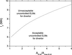
Figure 1. Range of plasma current for H-mode operation in ITER for which uncontrolled ELMs are acceptable (from the point of view of divertor PFC erosion) versus broadening of the divertor ELM power flux footprint (with respect to the divertor power flux footprint between ELMs).
Download figure:
Standard image High-resolution imageFor conditions in which the uncontrolled ELMs would exceed the limits posed by divertor erosion, ELM control will be required in ITER. This can be achieved by the suppression of type-I ELMs with three-dimensional (3D) fields or by the controlled triggering of ELMs, taking advantage of the inverse dependence of the ELM energy loss on the ELM frequency (fELM) [10]:

where PSOL is the power flow out of the main plasma into the scrape-off layer (SOL). The expected uncontrolled ELM frequency and the required minimum ELM frequency for controlled ELMs for a range of values of the ELM power footprint broadening are shown in figure 2.
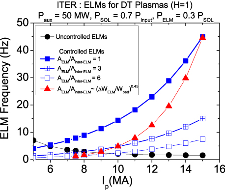
Figure 2. Expected uncontrolled ELM frequency in ITER versus plasma current for H = 1 DT H-modes and required minimum ELM frequency for controlled ELMs for various assumptions regarding the ELM power flux footprint broadening. These assumptions include a fixed broadening for all current levels and a decreasing level of broadening as the ratio of the controlled ELM energy loss to the plasma energy decreases ∼(ΔWELM/Wped)0.45 from a AELM/Ainter-ELM = 6 at 7.5 MA to AELM/Ainter-ELM = 1 at 15 MA.
Download figure:
Standard image High-resolution imageIt is important to note that the evaluation shown in figures 1 and 2 includes assumptions not only on the broadening of the ELM power flux footprint at the inner and outer divertors (assumed to be the same) but also on other important key parameters determining the magnitude of the divertor target ELM power flux, which have been derived for ITER on the basis of observations and scalings from experimental devices. Namely, (a) the timescale for ELM energy deposition is assumed to be determined by the ion parallel transport timescale along field lines in the SOL, in agreement with experiments [5], (b) the SOL power flux width between ELMs is assumed to scale as
 [11] in H-mode in ITER with λp(15 MA) = 5 mm and (c) the in/out ELM energy deposition asymmetry is assumed to be 2 : 1, in agreement with experimental results [12, 13]. If other assumptions are used to derive the ELM divertor power flux characteristics, the magnitude of Ip for which uncontrolled ELMs do not lead to unacceptable divertor erosion in ITER would change from those in figures 1 and 2.
This paper is organized as follows: section 2 describes a re-evaluation of the ELM control requirements in ITER for acceptable divertor and first wall erosion and additional requirements for W accumulation control. In this section, the control approach analysed relies on the increase in the ELM frequency above its natural or uncontrolled level rather than in the achievement of ELM suppression or ELM-less plasma regimes (such as the QH-mode [14]). Section 3 describes progress in the evaluation of ELM power fluxes to the divertor and first wall using non-linear MHD modelling which, in turn, provide new guidelines to refine the ELM control requirements described in section 2. Section 4 describes progress in the determination of pellet requirements for reliable ELM triggering in ITER following the control approach described in section 2 and an assessment of compatibility issues with ITER operational scenarios (mainly fuel throughput). Section 5 describes the application of resonant 3D fields for ELM control in ITER H-modes with emphasis both on the capabilities of the system for ELM suppression on the basis of empirical scalings and on compatibility issues with ITER operational restrictions (mainly fuel throughput, stationary divertor power handling and erosion and possible effects on W accumulation control). Section 6 evaluates the capability of the ITER in-vessel Vertical stability (VS) coil set to trigger ELMs by vertical plasma position oscillations as a tool to increase the ELM frequency for W accumulation control. Finally, section 7 summarizes the results and draws conclusions. A detailed discussion of the physics modelling for ITER addressing the issues described in sections 3–5 can be found in the following papers [15–18].
2. ELM control requirements in ITER for avoidance of uncontrolled erosion of first wall and divertor PFCs and for W impurity control
The analysis shown in section 1, which led to the formulation of the original ELM control requirements in ITER (for both a CFC/W and a full W divertor) and to a first assessment of the available ITER operational scenario with uncontrolled ELMs described in [3], has been further developed to include two additional factors: (a) the control requirements to avoid damage/excessive erosion of the ITER first wall and (b) the ELM control requirements associated with the operation of ITER with a W divertor, which was originally foreseen for the beginning of nuclear operations (DD and DT plasmas) and is now being considered also for the start of ITER operation in the non-nuclear phase (H and He plasmas) [1, 19]. As mentioned in the introduction, the ELM control approach analysed in this section relies on the increase of the ELM frequency above its natural or uncontrolled level rather than in the achievement of ELM suppression by 3D resonant field perturbations or ELM-less high plasma confinement regimes (such as the QH-mode). An evaluation of the potential for W control in ELM-suppressed plasmas by 3D resonant field perturbations in ITER is described in section 5.
Broadening of the ELM power flux footprint at the divertor allows an expansion of the H-mode operational range (in terms of Ip) for which uncontrolled ELMs would be acceptable, as shown in figure 1. However, if the processes that lead to the ELM footprint broadening at the divertor have a similar effect on the SOL, this would lead to an increase in the energy deposited by the ELM on ITER's main wall. The ITER first wall PFCs are made of Be elements which have a much lower erosion/damage threshold than those of W foreseen for the divertor, both in terms of plasma impact and power loads. It is thus possible that, for some conditions, excessive erosion of the first wall PFCs rather than of the divertor could determine the limit to uncontrolled ELM operation and hence the ELM control requirements in ITER. Determination of the physics mechanisms leading to the ELM energy fluxes to the divertor and main wall and the consequences for ITER remains a subject of R&D. For details on the progress of modelling of ELM power fluxes to the divertor and main wall of ITER the reader is referred to section 3 of this paper and to [15].
An evaluation of the limits to uncontrolled ELM operation on ITER imposed simultaneously by the W divertor and the Be first wall for various levels of ELM power flux broadening is shown in figure 3. It is important to note that these limits scale with Ip in the opposite way for the Be wall than for the W divertor. For the same ΔWELM, a larger Ip leads to a narrower effective e-folding length for the ELM power flux and thus a higher ELM power flux to the W divertor target and to a lower ELM power flux at the Be wall. The curves in figure 3 are evaluated for (a) a distance between the separatrix and the first point of contact of SOL field lines with the first wall corresponding to 5 cm mapped to the outer midplane (which is close to the minimum clearance foreseen for ITER operation), i.e. a quasi-double null (QDN) configuration, (b) an angle of incidence of the field lines on the first wall panels in the upper wall region of 7° and (c) assuming that the number of plasma filaments that are produced at each ELM and reach the first wall is on the average 10, which is compatible with the expectations for edge plasma stability in ITER [15, 20].

Figure 3. Limits to the acceptable ELM energy loss (ΔWELM) for the W divertor and the Be first wall for ITER H-modes versus plasma current for various assumptions regarding the broadening of the ELM power flux width. The expected uncontrolled ELM energy loss is shown for comparison. A midplane separatrix–wall distance of 5 cm (typical of a QDN configuration), an average of 10 filaments per ELM and an average angle of incidence of 7° for the field line on the upper region of the ITER first wall are used for this evaluation.
Download figure:
Standard image High-resolution imageFigure 3 shows that for an ELM power flux footprint broadening in the range of ∼3–6, an acceptable PFC erosion of the Be first wall in ITER by uncontrolled ELMs in the QDN configuration would limit the level of Ip in H-mode to ∼7 MA, which is lower than that expected from the divertor considerations alone (8.0–9.5 MA, see figure 1). However, in contrast to the divertor, ELM loads to the first wall can be controlled by adjusting the plasma–wall clearance, so that by operating ITER with a separatrix–first wall distance of ∼10 cm (expected to be more typical of single null (SN) operation in ITER) the ELM first wall loads can be decreased to the point in which again divertor erosion sets the limit for the tolerable Ip in H-mode at which ITER can operate without ELM control, as shown in figure 4.

Figure 4. Limits to the acceptable ELM energy loss (ΔWELM) for the W divertor and the Be first wall for ITER H-modes versus plasma current for various assumptions regarding the broadening of the ELM power flux width. The expected uncontrolled ELM energy loss is shown for comparison. A midplane separatrix–wall distance of 10 cm (typical of a SN configuration), an average of 10 filaments per ELM and an average angle of incidence of 7° for the field line on the upper region of the first wall are used for this evaluation.
Download figure:
Standard image High-resolution imageIn addition to the avoidance of excessive PFC erosion, ELM control may be needed in ITER in order to prevent the increase in the core concentration of impurities, in particular of W produced by plasma–wall interactions at the divertor target. An excessive W core plasma concentration can affect the H-mode performance and/or cause a return to L-mode due to excessive core radiation and, in some cases, even a plasma disruption. The beneficial effect of ELMs in preventing this contamination is observed during operation with high-Z divertor and main wall PFCs in present tokamaks. High-Z impurities produced by plasma–wall interactions are observed to accumulate at the edge of the confined plasma between ELMs and are effectively expelled by the ELMs [21, 22]. A minimum value of fELM is thus required to prevent W accumulation in the main plasma to occur [21, 22].
For the initial ITER operation during the non-active phase (H and He plasmas) the plasma current/field will be limited to ∼7.5 MA/2.65 T in H-mode due to the expected H-mode power threshold scaling with plasma species/isotope mass and the toroidal field and the available additional heating power level [1]. Under these conditions, uncontrolled ELMs are not likely to cause unacceptable divertor erosion or melting, as shown in figures 1, 3 and 4. However, W will be produced by physical sputtering due both to the plasma in contact with the divertor target between ELMs and by the ELMs themselves. As discussed above, a minimum ELM frequency will be required in ITER to maintain an appropriate W concentration in the main plasma. This applies to both to non-active and active operational phases in ITER. It cannot, in principle, be assumed that the minimum ΔWELM and associated fELM required to avoid excessive divertor erosion (shown in figure 2) will also be sufficiently high to provide the appropriate ELM-driven W impurity outflux needed to maintain an acceptable main plasma W concentration in ITER.
An initial evaluation of the required level of ELM control to maintain an acceptable W concentration of the main plasma has been carried out by extrapolating present experimental results of the effective W divertor shielding in ASDEX-Upgrade [23] and evaluating the expected W divertor influxes in ITER caused by physical sputtering between ELMs and by the ELMs themselves. It is important to note that in these evaluations it is assumed that the only mechanism for W production is physical sputtering. Thus, the requirements derived for W impurity control on this basis need to be compared with those for divertor erosion control (i.e. melting avoidance) derived above to determine which of the two control requirements (erosion control or main plasma W impurity control) for ELMs will set the most strict ELM control requirements for each operation condition in ITER. The W divertor sputtering source for ITER can be derived according to the following procedure/assumptions:
- (a)For the phases between ELMs, the plasma flux to the divertor is derived on the basis of B2-Eirene simulations for 15 MA Q = 10 plasmas [24] extrapolated to lower currents under the assumptions that (i) a low plasma temperature is maintained at the divertor (to minimize W sputtering and stationary divertor power loads) so that the divertor remains close to detachment and the W physical sputtering yield remains under ∼10−5, as seen in tokamak experiments for these conditions [25, 26], (ii) the separatrix density is maintained at a fixed fraction of the Greenwald limit (nsep/nGW ∼ 0.33), (iii) the edge power flow scales as
 with λp(15 MA) = 5 mm and (iv) the dominant energy transport mechanism in the SOL is electron conduction along the open magnetic field lines.
 - (b)For the W sputtering source during ELMs it is assumed that particles expelled by the ELMs originate from the pedestal region in ITER and thus with multi-keV energies, for which the W sputtering yield is ∼10−2. The ratio of the number of particles expelled by the ELM to the main plasma particle content is assumed to be independent of the total ELM energy loss, as found in the experiment [10, 27]. The value of this ratio is taken to be 2.5% for ITER, which is within the typical range for type-I ELM particle losses found in present experiments [5, 28, 29]. The precise value of 2.5% is determined by the need to provide core plasma fuelling to replace the particle losses from controlled ELMs in 15 MA Q = 10 plasmas and the maximum fuel throughput limit of 1023 s−1 for 500 s burn in ITER [30]. If the particle losses caused by ELMs in ITER would exceed such a value by a significant factor the burn length and/or the pulse repetition rate would need to be adjusted to maintain the same maximum throughput limit on average, which is dictated by the ITER tritium re-processing capabilities and not by the fuelling capabilities in ITER.
The screening of the W source in ITER is derived both from the experimental results obtained in ASDEX-Upgrade [23], showing a screening factor of ∼600 for W entering the main plasma with respect to the divertor source, and from the physics guidelines derived from ASDEX-Upgrade [21] to describe the key factors controlling W screening. The latter is determined in ASDEX-Upgrade by the ratio of the time required for W to enter into the core plasma beyond the pedestal and the repetition time of the ELMs (1/fELM), which cause the W to flow out from the main plasma. The scaling of screening with the ratio of these two times is approximately linear so that, for ITER, the following relation is adopted:

where SW is the W divertor source screening and τW is the transport time for W to enter the confined plasma. The coefficient in equation (2) is derived from the following typical values from ASDEX-Upgrade [21] (τW = 5.7 ms and fELM = 100 Hz) for the measured W divertor source screening of 600 under such conditions [23].
It is important to note that in this formulation the contribution of prompt re-deposition of W at the divertor to its effective screening is assumed to be of the same proportion in ASDEX-Upgrade and ITER. This is likely to be an underestimate for ITER, as the expected divertor densities in ITER will be higher than those in ASDEX-Upgrade leading to a shorter neutral W ionization mean free path in the divertor and to a larger prompt-redeposited fraction of W in ITER than in ASDEX-Upgrade [31]. Thus, equation (2) in fact provides a lower estimate for the screening of W produced at the divertor in ITER, at least as far as the contribution of the prompt re-deposition is concerned.
The time required for W to enter the confined plasma (τW) comprises two components: (a) the time for W to be transported from the PFCs where it is originated to the plasma separatrix and (b) the time for W to be transported across the pedestal plasma to penetrate into the core plasma. When τW is long compared to the ELM repetition time, transport of W into the core plasma is very ineffective since there is insufficient time for W to penetrate from the divertor through the pedestal region into the core plasma between ELMs [21, 22].
Although the physics picture for W transport and screening adopted for ITER follows the same physics principles as that describing the results in ASDEX-Upgrade, the results of its application are in fact different due to physical differences between the two devices. The main contributor to core plasma contamination in ASDEX-Upgrade is W produced by the interaction of the plasma with the main chamber PFCs [21]. In this case W needs to cross the SOL plasma to reach the separatrix so that a longer time for W to cross the SOL improves its screening. This time is determined by the competition between radial inward transport and the parallel loss along the field line to the divertor, so that a short timescale for parallel loss prevents W from reaching the separatrix from the main wall. As a consequence, a short parallel loss time increases the effective radial transport time of W to the confined plasma and increases the effective screening of W in the SOL in ASDEX-Upgrade. In contrast, in ITER W will be produced only at the divertor (the main chamber is armoured with Be) and will reach the main plasma separatrix by parallel transport in the SOL from the divertor target. In this case, a short parallel transport time facilitates W penetration into the main plasma and decreases the effective screening for W impurities originating at the divertor. This is the opposite effect to that for W produced at the main wall.
The scaling of the transport physics processes for parallel transport in the SOL and for transport of W across the pedestal plasma (required for its penetration beyond the region from which ELMs can expel it) leads to the result that, for ITER, the longest timescale for W transport is that of transport across the pedestal, unlike in ASDEX-Upgrade. Plasma separatrix temperatures in ITER are expected to be in the range 200–350 eV for H-mode operation [24] while in ASDEX they are typically ∼100 eV [21] so that, for similar edge q95, the parallel transport times are thus only a factor of ∼2 larger in ITER than in ASDEX-Upgrade

 . On the other hand, W transport across the pedestal is expected to be very slow in ITER due to the scaling of impurity cross-field transport in the pedestal region with machine size. In experiments, cross-field transport of impurities in the H-mode pedestal is found to be very well described by neoclassical physics [32]. Assuming that the same physics process will dominate W cross-field transport at the ITER pedestal, the value of the inward W pinch velocity for 15 MA Q = 10 conditions [21] is expected to be only
 requiring 33 ms for W to cross through the ∼6 cm pedestal plasma expected in ITER [20]. This needs to be compared with the value of
 , which describes pedestal W transport in ASDEX-Upgrade requiring 0.2 ms to travel through the ∼1.5 cm pedestal plasma [33], and which is thus negligible compared to the parallel transport time of ∼6 ms.
This physics model is applied to evaluate the expected W core influx for H-mode conditions in ITER. The corresponding pedestal W concentration is derived on the basis that ELMs expel a fixed fraction of the plasma particle content (∼2.5%, which is compatible with fuel throughput requirements in ITER) and that ELMs are the dominant mechanism for expulsion of W from the core plasma. This provides a minimum value for the core W concentration on the basis of its pedestal value, as the W concentration profile is found to have a similar or higher peaking than that of the main plasma ion density in the core plasma for conditions in which there is no W accumulation [34]. The resulting gross W influxes (i.e. before the screening correction is applied) into the edge plasma and the resulting W concentration are shown in figure 5 for uncontrolled ELMs in ITER. An important implication of this figure is that, although uncontrolled ELMs in low plasma current H-modes up to 8.0–9.5 MA might be acceptable from the W divertor erosion point of view if the ELM power footprint shows significant broadening factors of 3–6, the expected low frequencies of such ELMs (a few Hz, as shown in figure 2) would be insufficient to prevent a significant edge W concentration (∼10−4) under these H-mode conditions. Although recent results from ASDEX-Upgrade with strong electron heating have demonstrated that it is possible to sustain good H-mode performance for core W concentrations at the ∼10−4 level [35], termination of the H-mode and, possibly, even disruptions in ITER cannot be excluded at such high values.
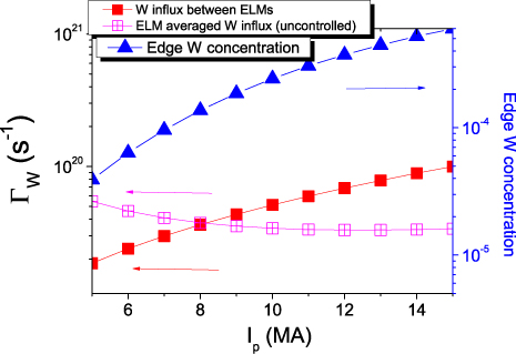
Figure 5. Expected gross (i.e. unscreened) W divertor influxes between and during ELMs in ITER for uncontrolled ELMs (PELM = 0.3PSOL and ΔNELM/Ntot = 2.5%) and resulting edge W concentration.
Download figure:
Standard image High-resolution imageThe same modelling assumptions are thus applied to evaluate the value of fELM that would be required to maintain the pedestal W concentration to a level of ∼2.5 × 10⁻⁵, which is found both to be safe in present experiments from the point of H-mode operation and is expected to be compatible with the required fusion performance of ITER plasmas [25]. The results are shown in figure 6 indicating that fELM in the range 15–20 Hz would be required in ITER to achieve this level of edge W concentration. This implies that, for low-current H-mode plasmas in ITER, W concentration control may impose more restrictive requirements in terms of ELM control than those for control of W divertor damage/excessive erosion, particularly if the broadening of the ELM power flux footprint at the divertor is large (3–6) under such conditions. For higher plasma currents, as required for the 15 MA Q = 10 and ∼12.5 MA Q = 5 hybrid scenarios in ITER, W divertor damage/excessive erosion avoidance sets similar or more strict ELM control requirements and these also satisfy the need to maintain a low W concentration. The weak dependence of the fELM required for W concentration control on Ip is due to the following physics assumptions: (a) the fact that ELMs themselves are the dominant source for W production for conditions in which the divertor remains cold between ELMs (which is in good agreement with experiment) [21, 26], (b) that W screening increases linearly with ELM frequency (also in good agreement with experiment [21]) and (c) that the time for W to travel from the divertor across the pedestal region into the core plasma is weakly dependent on Ip in the model described above.
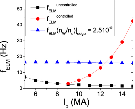
Figure 6. Expected ELM frequency for uncontrolled and controlled ELMs (evaluated for (AELM/Ainter-ELM ∼ (ΔWELM/Wped)0.45) in ITER H-modes and required ELM frequency to maintain an edge W concentration of 2.5 × 10⁻⁵ for range of plasma currents.
Download figure:
Standard image High-resolution imageThe results obtained for ITER are in line with expectations from present experiments when the required fELM for W accumulation avoidance is compared with the energy confinement time (as a proxy for core particle confinement time). To maintain a low W concentration in ITER fELM × τE = 25–50 is required, while experiments show that in order to avoid W accumulation in H-modes an ELM frequency larger than fELM × τE ⩾ 10 [21, 22] is required. Recent modelling studies carried out for ITER, with models previously applied to modelling production, edge transport and contamination of the core plasma by W in ASDEX-Upgrade, have demonstrated the validity of the approach followed above to evaluate the ELM control requirements to prevent W accumulation in ITER and confirmed the validity of the physics picture developed to evaluate W contamination and control by ELMs above [36–38]. These studies, however, produce results which are quantitatively different from those presented here; the ELM frequency required to prevent W accumulation (which leads to the loss of the H-mode in ITER by excessive core radiation in the sophisticated modelling) in these modelling studies is ∼20–25 Hz (i.e. fELM × τE = 35–70) for H-modes with plasma currents in the range Ip = 7.5–15 MA to be compared with the 15–17 Hz (i.e. fELM × τE = 25–50) obtained with the semi-empirical approach followed in this paper.
It is important to note that core W transport also plays a role in determining whether W accumulates in the core for a given level of edge W concentration so that a more precise evaluation of the ELM control requirements for W accumulation prevention in ITER requires a more refined model of the edge and core plasmas, which is described in [36–38].
In order to advance the understanding of the ELM characteristics and their control in ITER plasmas a two-pronged approach is thus followed: one involves the experimental/theoretical research at the ITER members's fusion facilities through their own programmes and that coordinated under the ITPA activities and the other the application of the models developed and, as far as possible, validated against the experimental results to the ITER plasma conditions. This paper provides an overview of progress in the latter set of activities, which are described in more detail in the following papers [15–18].
3. Non-linear MHD modelling of ELM power fluxes in ITER
In order to improve the understanding of ELM energy fluxes to PFCs, non-linear simulations of the ELM crash in ITER have been carried out with the JOREK non-linear MHD code, which includes the transport of energy from the main plasma onto the divertor and first wall PFCs [39]. Simulations have been carried out for the 15 MA Q = 10 plasma conditions in a SN plasma configuration. So far, relatively small ΔWELM for the ITER scale (1.5–4 MJ) have been obtained, which are much smaller than those expected from empirical scaling to ITER for these plasma conditions (∼20 MJ) [5]. Despite this, the simulations have provided key insights on the physics mechanisms that are responsible for the transport of energy from the main plasma to PFCs at the ITER scale and on their influence on the magnitude and spatial characteristics of the ELM fluxes. For the modelled case with ΔWELM ∼ 4 MJ, it is found that the non-linear growth of the MHD activity during the ELM crash creates an ergodic layer at the plasma edge (reminiscent of that obtained with edge magnetic field perturbations) leading to a direct connection between the divertor and the confined plasma and to a large conductive heat flux along these ergodized field lines (i.e. ELM losses are dominated by conduction) [15]. In contrast, for the smaller ELMs (∼1.5 MJ), the level of edge ergodization is much smaller and energy is lost from the confined plasma by the growth and expulsion of plasma filaments with little change to the plasma temperature (i.e. convective ELMs) [15].
Despite the different ELM energy transport mechanisms and the different detailed shapes of the divertor ELM power flux profiles (see figure 7), the effective area for ELM energy deposition at the outer divertor is similar (within a factor of 1.3) for both ELM simulations [15]. This corresponds to an effective broadening of the ELM divertor power flux of 1.4–2.8 with respect to the effective power footprint between ELMs. Such a broadening would increase the controlled ELM size for these conditions in ITER from 0.7 to 1.0–2.0 MJ due to the increase in the effective footprint for energy deposition for small-controlled ELMs by a factor of 1.4–2.8 with respect to the between-ELM power footprint, as shown in figure 3 (i.e. the comparison of the results for AELM = Ainter-ELM with AELM = 3Ainter-ELM for Ip = 15 MA in the figure). For the divertor targets, the dominant mechanism for ELM energy deposition changes with ELM type: parallel conduction in the ergodized edge for the larger ELMs versus energy loss along the 'intact' (i.e. as in between ELMs) poloidal field from detached filaments for the smaller ELMs. In contrast, the mechanism for ELM energy transport to the first wall is the same for the range of ΔWELM modelled so far for ITER and is associated with the number of particles expelled by the ELMs, which depends weakly on the total ELM energy loss in the JOREK simulations of ITER ELMs [15] and in the experiments [5]. This is the convection of energy in the radially propagating filaments which is then lost along the field line when filaments come in contact with the first wall components. JOREK simulations show that the magnitude of the ELM energy reaching ITER's first wall does not depend on the size of the total ELM energy loss within the range considered so far (for a detailed discussion on the filament dynamics leading to this result the reader is referred to [15]). The proportion of ELM energy deposited at the wall is ∼10% for ∼1.5 MJ ELM, which is consistent with a power e-folding length for the ELM power flux in the main chamber of ∼4.0 cm (i.e. ∼2.0–4.0 times as broad as the divertor ELM power footprint) but only ∼4% for the 4 MJ ELM, which is consistent with a power e-folding length for the ELM power flux in the main chamber of ∼2.8 cm (i.e. 1.1–2.2 times as broad as the divertor ELM power footprint). These modelling results already indicate that ELM power fluxes to the first wall in ITER may not be related in a straightforward way to ΔWELM nor to the effective broadening of the ELM divertor power flux footprint, as is assumed in the simplified model used to derive figures 3 and 4. Indeed these JOREK modelling results challenge the appropriateness of the direct extrapolation to the ITER scale of the empirical picture [7–9] that relates the divertor ELM power deposition area to the magnitude of the ELM energy loss and/or the peak ELM divertor power flux to the pedestal plasma parameters [7]. Further work is required, and is in progress, to compare in detail the predictions of the JOREK code against experiments with emphasis on two aspects that are key to the progress in the refinement of the evaluation of the maximum tolerable ELMs in ITER beyond that shown in figures 3 and 4; namely, (a) the sharing of the ELM energy flux between the inner and outer divertor targets and (b) the broadening of the inner divertor footprint during the ELM.
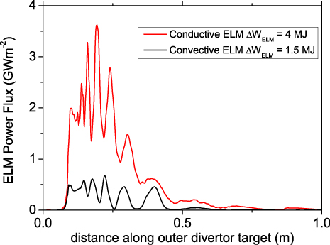
Figure 7. Peak ELM power flux for a 4 MJ conductive and a 1.5 MJ convective ELM versus distance along the outer divertor target modelled with the non-linear MHD code JOREK [15].
Download figure:
Standard image High-resolution image4. Modelling of controlled ELM triggering by pellet injection
Control of the fELM and ΔWELM by the injection of pellets is one of the two main ELM control schemes foreseen in ITER, which has been investigated thoroughly in several tokamaks (ASDEX-Upgrade, JET and DIII-D) [40–42]. A sketch of the ITER pellet injection geometry for ELM control is shown in figure 8. Recently, DIII-D has demonstrated the very high capabilities of this technique to reduce the ELM energy deposited at the divertor [42]. These DIII-D experimental results have achieved a reduction of the ELM energy deposited at the divertor by a factor of ∼12 for controlled ELMs by pellet injection compared to uncontrolled ones for the same discharge conditions (see figure 9 from [42]), i.e. an ITER-relevant range and with very minor effects on plasma confinement [42]. In addition to these very encouraging experimental results, several important issues need to be addressed regarding the application of this technique to ITER, which involve both the requirements for the pellet injection system as well as the compatibility of this ELM control technique with other ITER scenario requirements and operating restrictions. The key ones are (a) the required pellet size to reliably trigger ELMs and its implications for the fuel throughput associated with this technique, (b) the adequacy of the ITER pellet injection geometry (in the low-field side of the plasma above the X-point, as shown in figure 8) for ELM triggering, (c) the possible toroidal asymmetries of the divertor power flux for pellet-triggered ELMs and (d) the impact of this control technique on the pedestal and core plasma parameters and, thus, on plasma confinement and fusion performance.
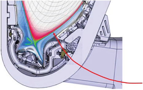
Figure 8. Injection geometry foreseen in ITER for the injection of pellets for controlled ELM triggering [30].
Download figure:
Standard image High-resolution image
Figure 9. Average ELM energy deposited in the divertor (a) and peak ELM heat flux in DIII-D (b) measured by the divertor infrared camera as a function of the pellet injection frequency (i.e. controlled ELM frequency) [42].
Download figure:
Standard image High-resolution imageModelling of ELM triggering by pellet injection has been performed with the non-linear MHD code JOREK that has been upgraded to include an appropriate description of the pellet ablation physics [16]. Before applying this model to ITER, its predictions have been compared with experiments in DIII-D in which ELMs have been triggered by injection of pellets at the outer midplane and above the X-point with ITER-like injection geometry [42]. JOREK simulations show that triggering of ELMs by pellet injection is caused by the toroidally localized high edge pressure regions produced by the localized deposition of particles by the pellet and their reheating by the plasma [39]. When the pressure in this localized edge region exceeds a threshold, ballooning modes grow non-linearly leading to ELM crash. Exceeding this pressure threshold implies that, for given pedestal plasma conditions, a minimum pellet size is required to trigger an ELM in the JOREK simulations, which is in agreement with experimental findings [41]. A comparison of the pellet size required to trigger an ELM in the JOREK modelling with DIII-D experimental results indicates that the number of particles required to trigger an ELM in the model is a factor of 2–3 times larger than that in the experiment. This is, to some degree, linked to the minimum size of the initial pellet ablation cloud that can be feasibly modelled with JOREK [16]. JOREK modelling also shows that the geometry of injection has an influence on the required pellet size for ELM triggering so that for injection above the X-point, the required pellet size modelled in DIII-D could be somewhat smaller than that for midplane injection (∼20% in linear dimensions that corresponds to 40% fewer particles) [16]. The reasons for this difference are currently under detailed study but an important factor is believed to be the flux expansion of the field lines along the pellet trajectory, which favours the more peripheral deposition of pellet particles and larger edge pressure gradients when it is injected in regions of high flux expansion [16]. Thus, the results from DIII-D modelling indicate that the ITER pellet injection geometry for ELM control is not disadvantageous in terms of the reduction of the fuel throughput requirements associated with this ELM control scheme compared with injection at the midplane. JOREK simulations for DIII-D show that a local increase in the maximum plasma pressure in the pedestal region of about a factor of ∼2.5 is required to cause the non-linear growth of ballooning modes and the triggering of ELMs.
Modelling of the divertor power flux for pellet-triggered ELMs in DIII-D shows that it has a sizeable non-toroidally symmetric peak (i.e. of similar magnitude to the separatrix strike point ELM power flux) away from the separatrix (3–4 cm) at the outer divertor target [16], which has also been observed at JET [43]. This secondary peak has n = 1 symmetry and it is caused by the expulsion of a plasma filament in the vicinity of the pellet injection location that takes with it a large fraction of the pellet-injected particles.
Application of JOREK modelling for pellet triggering of ELMs in ITER has proven to be very numerically challenging. This is due to the large edge temperatures expected in ITER, which lead to a large ablation rate of the pellet as soon as it enters the plasma and to the formation of very steep density profiles near the separatrix. The modelling performed so far has concentrated on the evaluation of the pellet requirements for ELM triggering in 15 MA Q = 10 plasmas. Other important aspects, such as the study of toroidal asymmetries for the divertor power deposition in pellet-triggered ELMs as well as the scaling of the pellet injection requirements for ELM triggering at lower plasma currents in ITER H-modes, remain the subject of on-going work. The results of the scans carried out so far indicate that a pellet size of 3.7 mm (corresponding to 2.0 × 10²¹ particles in the pellet) with an injection velocity of 350 ms−1 is required for the triggering of ELMs in 15 MA Q = 10 ITER plasmas, which is well within the capabilities of the ITER pellet injection system [30]. ELM triggering is achieved when the local increase in the maximum plasma pressure in the pedestal region is about a factor of 2.5 above that of the top of the pedestal before pellet injection, as shown in figure 10 [16], i.e. similar to the modelling results for DIII-D.
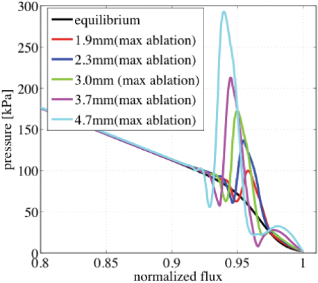
Figure 10. Maximum pressure perturbation as a function of the normalized poloidal flux for different pellet sizes (1.9, 2.3, 3.0, 3.7 and 4.7 mm) in the ITER 15 MA Q = 10 scenario [16].
Download figure:
Standard image High-resolution imageA preliminary evaluation of the pellet size and fuel throughput requirements for ELM control over a range of plasma conditions in ITER is carried out under a simplified set of assumptions:
- (a)the number of particles in the pellet required to trigger an ELM evaluated by JOREK is a factor of 2 larger than what will be required in real experiments in ITER. This is a direct consequence of the results of the quantitative comparison of JOREK results with the DIII-D experiments mentioned above (see [16] for more details);
- (b)the local increase in the pressure in the pedestal region caused by the pellet to trigger an ELM has to be a factor of 2.5 above the pressure expected at the top of the pedestal before an uncontrolled ELM is naturally triggered (from JOREK simulations for ITER and DIII-D); and
- (c)to first order, the pressure increase in the pedestal region scales with the square root of the number of particles in the pellet, as found for the ITER simulations in figure 10 [16]. This is in agreement with expectations from simple modelling that takes into account the formation of temperature gradients along the field line during the ablation process [44].
The resulting fuel throughput needed for ELM control by pellet injection in ITER is shown in figure 11. For the highest plasma current H-modes (Ip ⩾ 12.5 MA), required for DT operation at high Q in ITER, the fuel throughput that may have to be dedicated to ELM control to avoid W divertor damage (which is more demanding than that to avoid W accumulation for high-current H-modes in ITER, as shown in figure 6) is significant (∼40%) with respect to the total maximum particle throughput envisaged in ITER for 15 MA Q = 10 operation. This is well within the capabilities of the ITER pellet injection system and also well within the expected throughput that can be pumped/processed by the ITER pumping/de-tritiation systems [30, 45]. It has to be noted that a conservative approach has been followed for the ITER evaluation, i.e. a difference of only a factor of 2 in terms of total number of particles for the discrepancy between experiment and modelling of DIII-D has been applied for the ITER evaluation. Modelling work is on-going to resolve the quantitative discrepancies between JOREK modelling and experimental results from DIII-D as well as to evaluate the accuracy of the assumptions above regarding the scaling of the pellet size required to trigger ELMs in ITER for lower plasma current H-modes that will a allow a refinement of the evaluation carried out in figure 11.
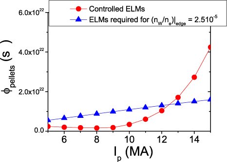
Figure 11. Required fuel throughput for pellet injection to control ELMs (evaluated for (AELM/Ainter-ELM ∼ (ΔWELM/Wped)0.45) in ITER H-modes and for the ELMs required to maintain an edge W concentration of 2.5 × 10⁻⁵ for range of plasma currents.
Download figure:
Standard image High-resolution image5. Application of edge magnetic field perturbations for ELM control in ITER
Control of ELMs by 3D edge magnetic field perturbations is the second main ELM control scheme foreseen in ITER. For this purpose, a set of 27 in-vessel six-turn coils (above, below and at the midplane) will be installed in ITER with a maximum current carrying capability of 90 kAt [46], as shown in figure 12. In addition, two in-vessel toroidal loops in the upper and lower parts of the device will also be installed in ITER [46] in order to provide appropriate VS control over a range of operating conditions.
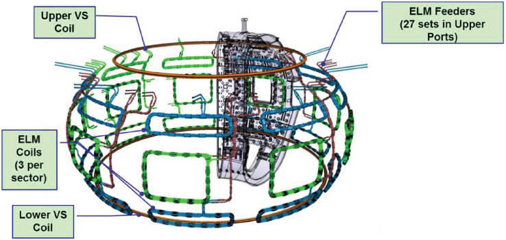
Figure 12. Geometry of the internal (in-vessel) coils for ELM control and for VS control. The ITER ELM control set of coils consists of three toroidal rows with nine window-frame type coils in each row (i.e. a 3 × 9 coil, with upper and lower rows in blue and middle row in green in the figure). The ITER in-vessel VS control set consists of two toroidal loops in the upper and lower parts of the device (in brown in the figure). Their integration into an ITER vacuum vessel sector is shown for illustration. Reproduced with kind permission from [46]. Copyright ANS 2013.
Download figure:
Standard image High-resolution imageExperimental progress in the area of research of ELM control by 3D fields has proceeded at a very fast pace [47–50]. This experimental progress is summarized in figure 13 showing the region of the operational space in terms of pedestal collisionality and edge density (normalized to the Greenwald limit) over which H-mode regimes without type-I ELMs have been achieved in various devices. Currently, the range of conditions over which elimination of type-I ELMs has been achieved covers the range of pedestal collisionalities and densities expected in ITER (the two cannot simultaneously be achieved in present experiments). However, a solid physics basis to explain why type-I ELMs are avoided under these experimental conditions and with the magnitude and structure of the 3D fields applied remains to be developed. Thus, a series of important physics issues regarding the processes that lead to the elimination of type-I ELMs by the application of 3D fields remain to be resolved. These influence both the requirements for the magnitude and structure of the 3D fields required in ITER for type-I ELM elimination as well as the compatibility of this scheme with ITER scenario requirements or operation restrictions and are the subject of intense experimental and modelling/theoretical R&D. A summary describing progress in these R&D activities is beyond the scope of this paper.
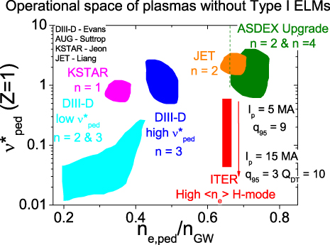
Figure 13. Operational range over which H-modes without type-I ELMs have been achieved in present experiments by the application of 3D fields with various toroidal symmetries (from results in [47–51]).
Download figure:
Standard image High-resolution imageIn the absence of a solid physics basis, the capabilities of the ITER ELM control coil system are evaluated on the basis of the empirical criterion derived from DIII-D ITER-like plasmas in which type-I ELM suppression has been achieved [52]. This evaluation is performed for a range of plasma scenarios and phases among the currents in the three coil rows, including cases in which coils cannot be used due to malfunction [17].
This evaluation is carried out in the vacuum approximation, i.e. by the linear superposition of the plasma magnetic field and the field from the coils unmodified by the plasma. However, both in ITER and in present experiments, the plasma is expected to modify the resonant field that the coils create inside the plasma. As mentioned above, the development of a physics criterion for ELM suppression including this effect and the modelling of the plasma response for ITER plasmas in toroidal geometry remain a subject of R&D and will be taken into account in future studies to refine the results presented below. A detailed physics discussion of shielding/amplification of 3D resonant perturbations including both shielding and amplification of the applied resonant component of the applied field as well as effects on plasma rotation of the non-resonant fields which are unavoidably applied together with the resonant fields in this scheme is beyond the scope of this paper. The reader is referred to recent studies for further details on the present understanding on this topic [53–56]. In these studies the key role of the net electron perpendicular velocity on shielding of the resonant components of the applied external fields by induced currents in the plasma is discussed. These studies show that low values of the net electron perpendicular velocity, for a given plasma resistivity, lead to poor shielding. The net electron perpendicular velocity is determined by the competition of the electron diamagnetic velocity and the electron poloidal rotation velocity caused by the radial electric field; the latter being determined by the ion pressure and temperature gradients and the plasma toroidal rotation velocity. In this respect, it is important to note that the edge toroidal rotation frequency expected in ITER is rather low (few krad s−1) due to the low torque input provided by the additional heating systems (the neutrals injected by the ITER neutral beam injection (NBI) have an energy of 1 MeV and a total injected power of 33 MW). This may lead to a sizeable net electron perpendicular velocity over the pedestal plasma region in ITER unlike, for instance, in suppressed ELM regimes in DIII-D [53]; the competition between the lower plasma resistivity and the net electron velocity resulting from the electron diamagnetic velocity, the edge plasma gradients and the low toroidal rotation in ITER will eventually determine the resulting shielding of the resonant components of the external magnetic fields applied for ELM control in ITER (see, for example [53, 54]).
A large shielding of the 3D applied resonant fields in ITER could decrease the margins in ELM coil current (with respect to the maximum 90 kAt) required in ITER to achieve a given level of edge magnetic field perturbation for ELM suppression from the vacuum approximation presented here. It should be noted, however, that using a low n (n = 1, 2) for the symmetry of the applied 3D fields in ITER to obtain a higher level of edge magnetic field perturbation for a given level of applied current in the coils, as done in present experiments [49, 50], may lead to excessive breaking of plasma rotation due to the non-resonant fields applied together with the resonant fields with these low-n perturbations and to mode-locking due to the low input torque mentioned above and to the values of q95 (∼3–4) which are required in ITER to achieve a high-Q scenario.
The empirical criterion used to evaluate the ITER ELM control coil set performance and flexibility is based on a similar physics argument to its original formulation [52] (i.e. the need for a minimum width for a stochastic layer at the plasma edge by the overlap of magnetic islands created by the external perturbation) but has been refined to incorporate the multiple toroidal harmonics which are generated by the ELM control coils in ITER [17]. An evaluation of the coil current required to achieve the above-mentioned empirical criterion by applying currents in the ITER ELM control coils with a cosine toroidal waveform with n = 4 and n = 3 symmetry is shown in figures 14(a) and (b) [17]. Since it is not possible to produce a pure n = 4 waveform with nine coils, the edge island structure created in such a configuration is more complex than that expected from a pure n = 4 perturbation and contains higher n harmonics. These higher n harmonics contribute to closing the gaps between islands allowing the achievement of the empirical ergodization criterion at a lower current in the coils than with an n = 3 waveform. On the other hand, for the same reason, the n = 4 waveform is likely to lead to more toroidally asymmetric power/particle fluxes at the divertor (see below for further discussions). In addition, it is expected that higher n harmonics will be more effectively shielded by the plasma [53]. Therefore, it might be the case that the advantage, in terms of required current in the coils, of using an n = 3 or n = 4 waveform for ELM control in ITER derived from this vacuum modelling may not apply when plasma response effects are included. Increasing the current above the required minimum value to meet the ELM suppression empirical criterion increases not only the width of the ergodic layer but also the range of relative toroidal phasings between the upper–middle–lower rows of the ELM control coils which can meet the criterion [17]. This relaxes the need for alignment between the edge magnetic field and the perturbation applied, which needs to be very precise for the lowest coil current levels required to meet the empirical criterion (for a detailed study the reader is referred to [17]). Such an alignment could be difficult to maintain during phases of the ITER discharges in which the plasma current increases or decreases at a fixed magnetic field (i.e. ramp-up or ramp-down phases in H-mode).
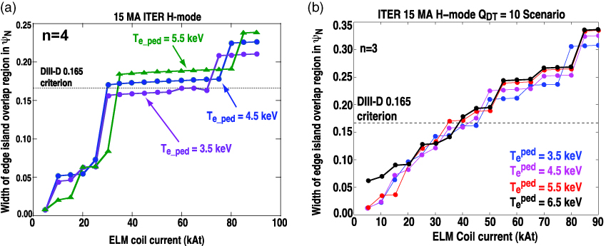
Figure 14. (a) Width of the edge ergodic layer (as defined by the island overlap region) in normalized poloidal magnetic flux versus maximum coil current for a current waveform with n = 4 toroidal symmetry [17]. (b) Width of the edge ergodic layer (as defined by the island overlap region) in normalized poloidal magnetic flux versus maximum coil current for a current waveform with n = 3 toroidal symmetry. Reproduced with kind permission from [17]. Copyright IAEA, Vienna 2013.
Download figure:
Standard image High-resolution imageThe flexibility in the ITER ELM control coil set allows maintaining the system's performance in case of malfunction of some of the in-vessel coils. Evaluations carried out for the 15 MA Q = 10 scenario show that for the case in which 5 of the equatorial coils are not used, operation with a maximum current of 70 kAt in the remaining 22 coils should produce a similar width of the ergodized layer and operational space (in terms of perturbation alignment) as that achieved with all the 27 coils operational with a maximum current of 50 kAt [17]. Studies for a range of ITER scenarios, including lower current H-mode operation at 7.5 MA q95 = 3 foreseen in the initial H/He phase [1], show that, for n = 3 perturbations, the coil current required to meet the empirical criterion scales, to first order, linearly with the plasma current [17]. Deviations from this rule are associated with changes in the edge magnetic shear due to the pedestal pressure gradient affecting the bootstrap current and for operation at higher q95 (i.e. lower plasma current at the maximum toroidal field of 5.3 T in ITER).
Toroidal asymmetries of the power and particle fluxes to PFCs associated with the application of 3D fields have been found in experiments [57], and have been modelled by EMC3-Eierene for ITER [18, 58]. This code has also been applied to model toroidally asymmetric fluxes in DIII-D [59] and ASDEX-Upgrade [60]. The perturbation created by the ELM control coils in ITER leads to the splitting of the power flux at the divertor and to toroidally asymmetric power deposition away from the separatrix. The structure of the power flux resembles the plots of the connection length of the field lines at the plasma edge revealing the well-known homoclinic tangles and strike point lobes at the divertor target [61] (see figures 15(a) and (b) for the connection length plots for n = 4 and n = 3 perturbations, respectively, and figures 15(b) and (c) for a comparison of the structures of the power flux and of the connection length with n = 3). The power flux splitting into various lobes widens the region over which the high power flux is deposited at the divertor target, as shown in figure 15(c) for a worst possible case with 100 MW SOL power flow in ITER and no divertor radiation (peak divertor flux of ∼10 MW m−2). This level of power flux would lead to a peak heat flux at the divertor target of ∼24 MW m−2 in the absence of ELM control coil perturbation using the same modelling assumptions for anomalous edge transport as those in the 3D simulations [18, 58]. In this respect, the use of an n = 3 perturbation symmetry with a system of nine coils per row in ITER instead of n = 4 is advantageous with regards to getting a more symmetric distribution of footprints in the toroidal direction, as shown in figures 15(a) and (b).
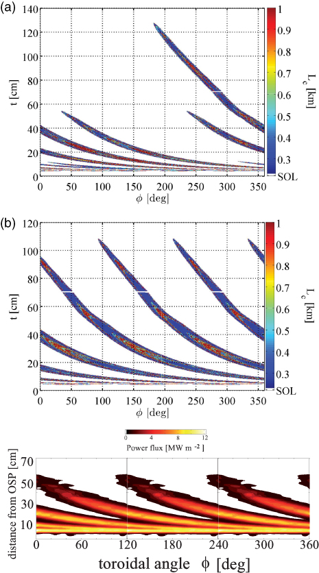
Figure 15. (a) (top) Connection length of the field lines arriving at the outer divertor target in ITER for a perturbation with n = 4 symmetry and 90 kAt maximum current in the ELM control coils. Reproduced with kind permission from [17]. Copyright IAEA, Vienna 2013. (b) (middle) Connection length of the field lines arriving at the outer divertor target in ITER for a perturbation with n = 3 symmetry and 90 kAt maximum current in the ELM control coils [17]. (c) Outer divertor power flux for an edge power flux PSOL = 100 MW with no divertor radiation and an ELM coil perturbation similar to that in (b) [18].
Download figure:
Standard image High-resolution imageIn addition to affecting the toroidal symmetry of edge power fluxes, the large ergodized region present in the modelling using the vacuum approximation has substantial effects on the thermal confinement of the core plasma and would lead to a collapse of the core temperature by factors of 2 or more in ITER, but such effects are not seen in the experiment [18, 58]. This temperature collapse in ITER modelling is avoided by the inclusion of the effects of plasma shielding in these calculations in a simplified way [62]. Modelling for ITER has shown that, for ITER 15 MA Q = 10 plasma conditions, significant shielding effects are expected for resonant modes with m ⩽ 7, which affects both the extension of the ergodized zone into the confined plasma region and the radial extent of the divertor power flux lobes [18]. Inclusion of these effects in EM3C-Eierene modelling prevents the temperature collapse observed in the simulations with the vacuum approximation but also decreases the spreading of the divertor power flux by the application of the coils found there. Thus, when plasma shielding effects are included, the peak divertor power flux is ∼17 MW m−2 (no divertor radiation), which corresponds to a reduction in the peak heat flux by a factor of ∼1.5 compared with conditions without current in the ELM control coils. This is smaller than the factor of ∼2.5 reduction found for modelling done in the vacuum approximation. More details on the modelled power and particle fluxes at the ITER divertor for a range of scenarios and divertor conditions (including high plasma radiation) can be found in [18].
The creation of an ergodic layer at the plasma edge leads to a direct connection between the core plasma and the divertor target, which has an effect not only on the power exhaust, as described above, but also on the core plasma particle confinement. This is identified in experiments as a density pump-out when type-I ELMs are suppressed by 3D fields [47]. The ergodized zone in the pedestal region is found to cause a significant direct loss of particles from the main plasma to the divertor target along the ergodized field lines in the simulations carried out for ITER even when plasma shielding is included. For the modelling including plasma response effects, this additional particle loss requires an increase in the core fuelling rate by ∼25% (∼few 1022 s−1) which should be provided by pellet fuelling given the low efficiency of gas fuelling in ITER [45]. This additional core fuelling demand is within the capabilities of the ITER fuelling system [30] but is, nonetheless, not a negligible increase. In this sense, the additional pellet fuelling required for ELM control by 3D magnetic field perturbations in ITER is comparable to the fuel throughput requirements for ELM control by pellet triggering described in the previous section.
This increased level of particle transport at the edge of the confined plasma is favourable to prevent W contamination of the main plasma in the absence of type-I ELMs, as demonstrated experimentally in ASDEX-Upgrade [48]. The increased level of core fuelling rate by 25% expected for ITER when 3D fields are applied can be interpreted as an increase in the effective plasma anomalous diffusion coefficient (D) in the pedestal region by a similar amount. The level of the anomalous diffusivity in the ITER pedestal is expected to be close to that predicted for neoclassical ion transport (D ∼ 0.1 m2 s−1 for 15 MA Q = 10 H-modes) [63]. Therefore, the increase in the effective anomalous transport by 3D fields in ITER for these conditions amounts to ΔD ∼ 0.025 m2 s−1. If, as expected, such anomalous transport enhancement affects the impurities as well, it implies an increase of a factor of more than 2 for the effective W diffusion coefficient (neoclassical + anomalous) in the ITER plasma pedestal compared with the neoclassical level alone
 for typical Q = 10 conditions in ITER [21, 37]) and, correspondingly, a sizeable decrease in the W ion density in the pedestal for a given W influx. Present experimental evidence in ASDEX-Upgrade [48] indicates that the enhanced W outflow caused by 3D fields is at least as efficient as type-I ELMs to provide core plasma W exhaust, which is in qualitative agreement with the above arguments for ITER. In this respect, it should be noted that recent QH-mode experimental results have also demonstrated the potential of the edge harmonic oscillation (EHO) associated with this H-mode operational regime to control core plasma contamination by medium-Z (fluorine) impurities [64]. A quantitative evaluation of present experimental findings regarding the effects of 3D fields on high-Z impurity transport in the pedestal region of H-mode plasmas is required in order to refine the quantitative evaluation of its effectiveness for core plasma W exhaust in ITER beyond the simple estimates above.
The existence of toroidally asymmetric power and particle flux structures at the divertor could potentially lead to localized erosion areas due to the large particle fluences expected at the ITER divertor. Such structures are found in experiments for all divertor conditions when 3D perturbation fields are applied, including the high-density and detached divertor plasma conditions expected in ITER [60, 61, 65]. In order to smooth them out, the possibility of rotating the ELM control coil perturbation is included in the ITER design. In such a case, it is important to avoid thermal cycling of the W/Cu interface within the divertor PFCs (see figure 16(a)) in the areas (where the divertor power flux is not toroidally symmetric) as the non-toroidally symmetric heat flux pattern rotates. To ensure sufficient lifetime of the W divertor PFCs, the frequency of rotation of the ELM coil perturbation is evaluated as a function of the peak heat flux in the non-toroidally symmetric lobes to ensure that the temperature at the W/Cu interface changes by less than 10% through the rotation (see figure 16(a)). This is considered a sufficiently low temperature variation to avoid a degradation of this bond by thermo-mechanical fatigue [66].

Figure 16. (a) Diagram for the ITER divertor W monoblock (dimensions in mm) showing the W/Cu interface in red whose temperature must be kept constant within a 10% range through the rotation of the 3D perturbation during stationary Q = 10 plasma conditions in ITER. (b) Normalized amplitude for the variation of the temperature at the Cu–W interface in the W monoblock versus rotation frequency of the heat flux pattern created by the application of the ELM control coils in ITER for various levels of peak heat flux density in the non-toroidally symmetric structures. Cases in which the power flux is evenly split between the lobe structures and cases in which the power flow is dominant to one lobe structure are shown. Note that the frequency of oscillation of the currents in the ELM control coils is n times higher (i.e.
 ).
).
Download figure:
Standard image High-resolution imageModelling of the heat flux diffusion into the divertor PFCs, taking as input the EM3C-Eirene results, has shown that a rotation of the complete power flux pattern with a frequency of ∼1 Hz is sufficient to achieve this goal even for the most conservative case in which the power splitting among lobes would be very asymmetric and the peak power flux in the dominant lobe with n = 4 would reach the 20 MW m−2 level. The level of 20 MW m−2 is chosen as a conservative upper value for the heat flux in the toroidally asymmetric heat flux lobe structures. In fact, experiments show that the peak heat flux for high density/detached conditions in the toroidally asymmetric lobes can be similar to the toroidally symmetric power flux at the separatrix strike point [60, 61, 65]. For ITER, the maximum power flux near the strike point that needs to be achieved by operation in detached divertor conditions is 10 MW m−2, which is determined by technological limits of PFCs. A factor of 2 higher peak fluxes in the toroidally asymmetric structures than at the strike point is considered as a conservative upper limit. Because of the n = 4 symmetry, a complete oscillation cycle in the coil currents leads to the movement of each lobe at the divertor by 90° in toroidal angle. Thus, the complete rotation of the heat flux pattern at
 , which is required to ensure the avoidance of thermal cycling of the monoblock bonding in the conservative case described above, requires an oscillation frequency of the currents in the coils at fcoil = 4 Hz (i.e.
). For a more realistic case, nearer to the experimental results, with a peak power flux of 10 MW m−2 and a similar peak power flux in all toroidally asymmetric lobes, a rotation frequency of the complete heat flux pattern of
, which is required to ensure the avoidance of thermal cycling of the monoblock bonding in the conservative case described above, requires an oscillation frequency of the currents in the coils at fcoil = 4 Hz (i.e.
). For a more realistic case, nearer to the experimental results, with a peak power flux of 10 MW m−2 and a similar peak power flux in all toroidally asymmetric lobes, a rotation frequency of the complete heat flux pattern of
 (corresponding to a frequency of the currents in the coils of fcoil = 1.0 Hz with n = 3) is sufficient, as shown in figure 16(b).
6. Use of vertical plasma movements for ELM control in ITER
Periodic vertical movements of the plasma have been used to trigger ELMs in a number of tokamaks and could be realized in ITER by the use of the in-vessel vertical stabilization coils. This is not considered to be a viable ELM control scheme for Q = 10 operation in ITER on the basis of the results of a previous evaluation [3, 4]. Therefore, the key purpose and design requirements of the in-vessel vertical stabilization coils and of their power supplies are to provide VS in ITER.
In this paper, we present a new assessment of the possible use of the in-vessel coils and of their power supplies (within the design requirements adopted for their main mission) for ELM control in lower plasma current (Ip = 5–10 MA) H-modes. This may be a useful back-up ELM control option in view of the possible need to control ELMs during the initial low-Ip H-mode operation to avoid W accumulation in ITER. In this operational phase, the two reference ITER ELM control schemes (pellet pacing and 3D edge magnetic field perturbations by in-vessel coils) will be commissioned and it is advantageous to have a system available (the vertical stabilization coils will be fully operational before H-mode operation is attempted) to prevent W accumulation during these initial H-mode experiments in ITER.
In this range of currents (Ip = 5–10 MA), the achievable peak-to-peak plasma vertical displacement can reach values within the range of ΔZ = 6–10 cm in ITER. This range is limited by the maximum current in the coils and the associated ohmic heating, which needs to be removed by circulating water inside the core of the hollow conductors that make up the coils [46]. At similar values of normalized plasma vertical displacements to those achievable in ITER (ΔZ/R ∼ (1.0–1.6) × 10−2) ELMs have been found to be triggered in several tokamak experiments [3, 4]. On the other hand, the maximum oscillation frequencies that can be achieved in ITER are in the range 20–30 Hz and this range is limited by the voltage that can be applied to the coils. The capabilities of the ITER VS coil set to oscillate the plasma vertical position are summarized in figure 17 for two assumptions regarding the maximum temperature allowed in the exit cooling water from the coils and the speed of the cooling water. For the lower temperature operation, a lower current can be applied to the coils (to match the ohmic heating to the cooling capabilities). This allows operation at higher frequencies (within the voltage limits of the power supplies) but with a lower peak-to-peak plasma vertical displacement. Assuming that such vertical plasma position oscillations lead to the triggering of ELMs in ITER, the achievable controlled ELM frequencies of 20–30 Hz are above those required to avoid W accumulation in low-current H-mode plasmas in ITER (see figure 6). This scheme could thus provide a potential scheme for W concentration control through ELM control in low-current H-modes in ITER.

Figure 17. Achievable peak-to-peak plasma displacement and maximum oscillation frequencies with the ITER in-vessel vertical stabilization coils versus plasma current for ITER H-modes. Two assumptions regarding the maximum temperature allowed in the exit cooling water from the coils and on the speed of the cooling water are considered.
Download figure:
Standard image High-resolution image
The major uncertainty that remains with regards to the application of this scheme in ITER is the development of a physics-based criterion for ELM triggering by this technique. In particular, it is important to determine if ELM triggering requires a minimum plasma displacement (i.e. the criterion followed to derive figure 17) or a minimum velocity (i.e. induced edge current). From the results in figure 17 alone it cannot be ascertained whether the induced edge currents for such displacements in ITER would be sufficient to cause the triggering of an ELM or not.
In this respect, it should be noted that if ELMs are triggered by induced edge currents in this scheme, the high ITER edge temperatures would result in large plasma current densities being induced at the edge by plasma movements, thus decreasing the requirements regarding the speed of the plasma vertical movements in ITER compared with present experiments, as we demonstrate below. The edge current density (jind) induced by a vertical movement of the plasma ΔZ with velocity vZ scales as
where η is the edge plasma resistivity, Bp is the edge poloidal magnetic field and δ is the skin depth. The magnitude of the edge induced current density can be compared with that of the edge bootstrap current density
 given by
where Bp is the edge poloidal magnetic field, Pped is the pedestal pressure, Δ is the pedestal width,
 is the pedestal neoclassical collisionality and
 is a multiplication factor that reduces the bootstrap current from its maximum value (for
 ) as the pedestal collisionality increases. As the ITER H-mode plasma pedestals are practically collisionless
 . The ratio of the induced current to the pedestal bootstrap current is, thus, given by
where βped is the pedestal beta poloidal, R is the major radius of the device and Tped is the pedestal temperature. If we assume that ELM triggering in ITER would require a similar ratio of edge induced current density to pedestal bootstrap current density to that in present experiments, then the figure of merit to evaluate the potential of the technique to trigger ELMs in ITER is given by
The first fraction on the rhs of equation (6) is weakly dependent on the size of the device, as Δ ∼ R and βped is found not to vary strongly for H-modes across experimental devices [67]. In contrast, the second fraction scales strongly with the inverse of the machine size. For low-collisionality conditions such that the edge bootstrap current is close to its maximum theoretical value
 , if we assume that the displacement of the plasma will be proportional to the plasma size (Δz ∼ R) and take into account that the pedestal plasma temperature scales with the machine size as Tped ∼ R(1to2) [67], we find that the velocity required for ELM triggering scales as
The values of the velocity for the vertical movement of the plasma in ITER can be evaluated from the typical frequencies/displacements that are achievable with the VS coil system in ITER: 20–30 Hz for a 10 cm peak-to-peak oscillation (see figure 17) which corresponds to a vertical velocity of the plasma of vZ ∼ 4–6 m s−1. Utilizing the above scaling in equation (7) to extrapolate to JET, this corresponds to an achievable velocity of 22–128 m s−1 in JET. Such values compare favourably with JET observations in which reliable triggering of ELMs by vertical plasma movements can be achieved at typical velocities ∼6–8 m s−1 [68], indicating that the induced currents for the achievable vertical velocities in ITER should be sufficient to trigger ELMs. It is also important to note that, in the event of problems, the recovery of vertical position control in a ∼7.5 MA H-mode for a displacement of ∼5 cm is not very challenging for the ITER in-vessel VS control system, which is designed to recover a ∼16 cm displacement for a 15 MA L-mode plasma [69].
Further experiments, modelling of experimental results and detailed modelling for ITER plasmas are required to determine whether the above physics picture for the edge induced currents is a valid and solid basis on which to extrapolate present experimental results on ELM triggering by vertical plasma movements to ITER. This will finally determine the potential of this technique as an alternative approach to ELM control for W impurity control in ITER low-current H-modes which has been identified in the analysis presented here.
7. Summary and conclusions
This paper describes recent progress in the determination of ELM control requirements for ITER operation from the non-active phase to Q = 10 in DT plasmas and in the evaluation of the performance/requirements of the foreseen ELM control in ITER, as well as of the operational issues associated with their application in ITER. ELM control requirements have been further developed from their initial formulation for ITER [3] to include the restrictions imposed on uncontrolled ELM operation in ITER by excessive erosion/damage of the Be first wall, beyond those imposed by the divertor. It has been found that broadening of the edge power flux during the ELM is beneficial to enlarge the operation range of ITER H-modes for which uncontrolled ELMs are acceptable from the divertor erosion point of view. However, the ELM power flux broadening may also lead to excessive power fluxes on the first wall Be components thus introducing additional limitations on uncontrolled ELM H-mode operation in ITER. As a consequence, the H-mode operational range with uncontrolled ELMs in ITER is found to be determined by either divertor or first wall considerations depending on the plasma configuration (single null with large clearance from separatrix to first wall or quasi- double null with reduced clearance). In this paper, it is shown that the range of acceptable H-mode operation with uncontrolled ELMs is limited to plasma currents under 9.5 MA even for the largest ELM power flux broadening considered (∼6) and the largest clearance from the separatrix to the main wall, thus under the requirements for Q = 10 operation.
In addition, it is also shown that the frequency of such uncontrolled ELMs with very broadened footprint (which makes them acceptable for excessive PFC erosion avoidance) in ITER is unlikely to be sufficient to prevent the accumulation of W in the main plasma. Therefore, operation with a W divertor in ITER imposes additional requirements for ELM control, as ELMs are expected to be key mechanism to provide W exhaust from the main plasma. Evaluation of the ELM control requirements to maintain an appropriate W concentration in ITER shows that these requirements are more demanding than those for excessive divertor erosion avoidance for H-modes up to a current level of ∼12.0 MA. Thus, W accumulation control is expected to determine the ELM control requirements in the initial phase of non-active ITER operation where H-mode scenarios will be limited to a plasma current of ∼7.5 MA by the required power to access H-mode confinement. Alternatively, the use of 3D edge magnetic field perturbations to achieve ELM suppression in ITER is expected to deteriorate particle transport in the pedestal region and thus also to provide an efficient means to increase W exhaust required for core plasma W accumulation control.
Non-linear MHD modelling of the power fluxes to ITER PFCs with the JOREK code has identified the two key mechanisms that determine the power flux to PFCs during ELMs: heat conduction along the ergodized field created by the non-linear MHD activity growth during the ELM (mostly to the divertor target) and radial convection (followed by loss along the field lines) of energy in plasma filaments expelled by the ELMs. Existing JOREK modelling results indicate that conductive losses decrease strongly with decreasing magnitude of the ELM energy loss (and magnitude of the MHD activity) while convective losses are weakly dependent on them. Work is in progress to compare these JOREK predictions for ITER with results from tokamak experiments. The results obtained so far indicate a weaker decrease in the ELM divertor power flux footprint width with decreasing ELM size for ITER than what is seen in the experiment. If confirmed, this could relax somewhat the requirements for ELM control to avoid excessive divertor erosion for high-current H-mode operation in ITER.
An evaluation of the expected performance of the ELM control schemes foreseen in ITER, namely controlled ELM triggering by pellet injection and ELM control/suppression by 3D fields created by in-vessel coils, has been carried out. For both cases the proposed implementations of these schemes in ITER are found to meet the needs for ELM control/suppression required for ITER. The application of either of these two ELM control schemes in ITER comes associated with an increase in the fuel throughput that, although compatible with ITER fuelling/pumping capabilities, is not negligible. In the case of pellet triggering of the ELMs, the increased throughput is associated with the injection of pellets required for ELM triggering while in the case of the 3D fields by in-vessel coils the increased throughput is needed to compensate for the particle confinement deterioration associated with the appearance on an ergodic layer at the edge of the main plasma created by the 3D fields. On the other hand, this enhanced core plasma particle outflow associated with ELM control in ITER (whether because of pellet injection or deteriorated particle transport with 3D fields) is expected to provide an efficient means to flush out W impurities and thus prevent W accumulation from occurring in ITER.
For both ELM control schemes, improvements of the physics basis are required to refine their application to ITER scenarios. In addition, several issues remain to be resolved regarding their compatibility with ITER scenarios for both schemes of ELM control. On the present basis, both schemes appear to have enough flexibility in their design and capabilities to cope with the remaining uncertainties of their application in ITER. For instance, the level of current in the in-vessel coils expected to be required for ELM suppression in ITER in 15 MA Q = 10 plasmas is sizeably smaller than the maximum current capability of the coils, which allows the system to cope with a moderate degree of misalignment between the edge field line and the magnetic field created by the coils themselves. This flexibility also allows the system to meet its design performance with a moderate number of inactive coils, in case of coil malfunction. Similarly, the possibility to power every coil independently allows the rotation of possible non-toroidally symmetric power/particle deposition patterns on ITER PFCs created by the application of the coils. This leads to the smoothing of power loads and localized erosion zones while preventing the thermo-mechanical fatigue of key bonds in the ITER divertor target W PFCs.
Finally, the capability of the ITER in-vessel vertical stability control coil set for controlled triggering of ELMs by vertical oscillations of the plasma position has been assessed. Although it is not its main mission, the ITER vertical stability coil set has been found to have promising capabilities for controlled ELM triggering in low-current H-mode discharges in ITER. This is based on present extrapolations of either the magnitude of the plasma movement achievable in ITER versus its size or of the magnitude of the edge induced current density versus the expected edge bootstrap current density in ITER. This ELM control scheme could be a useful tool for W contamination control in the initial phase of ITER operation while the two main ELM control schemes in ITER are being commissioned. A more precise assessment of the range of plasma currents over which vertical plasma oscillations would be applicable in ITER H-modes for ELM control awaits a more solid physics basis for the processes that lead to ELM triggering when this scheme is applied in present experiments.
While many issues in the area of ELM control require further R&D to develop a more robust physics basis on which to extrapolate them to ITER, the study presented here indicates that the schemes currently foreseen are designed to have enough flexibility to provide the required level of ELM control during all phases of ITER operation from the non-active phase to high-current/high-Q DT operation both from the ELM control point of view itself as well as with respect to their compatibility with ITER scenario requirements and operation restrictions.
The views and opinions expressed herein do not necessarily reflectthose of the ITER Organization or those of Fusion for Energy.