


Abstract
The MIT Plasma Science and Fusion Center and collaborators are proposing a high-performance Advanced Divertor and RF tokamak eXperiment (ADX)—a tokamak specifically designed to address critical gaps in the world fusion research programme on the pathway to next-step devices: fusion nuclear science facility (FNSF), fusion pilot plant (FPP) and/or demonstration power plant (DEMO). This high-field (⩾6.5 T, 1.5 MA), high power density facility (P/S ∼ 1.5 MW m−2) will test innovative divertor ideas, including an 'X-point target divertor' concept, at the required performance parameters—reactor-level boundary plasma pressures, magnetic field strengths and parallel heat flux densities entering into the divertor region—while simultaneously producing high-performance core plasma conditions that are prototypical of a reactor: equilibrated and strongly coupled electrons and ions, regimes with low or no torque, and no fuelling from external heating and current drive systems. Equally important, the experimental platform will test innovative concepts for lower hybrid current drive and ion cyclotron range of frequency actuators with the unprecedented ability to deploy launch structures both on the low-magnetic-field side and the high-magnetic-field side—the latter being a location where energetic plasma–material interactions can be controlled and favourable RF wave physics leads to efficient current drive, current profile control, heating and flow drive. This triple combination—advanced divertors, advanced RF actuators, reactor-prototypical core plasma conditions—will enable ADX to explore enhanced core confinement physics, such as made possible by reversed central shear, using only the types of external drive systems that are considered viable for a fusion power plant. Such an integrated demonstration of high-performance core-divertor operation with steady-state sustainment would pave the way towards an attractive pilot plant, as envisioned in the ARC concept (affordable, robust, compact) (Sorbom et al 2015 Fusion Eng. Des. submitted (arXiv:1409.3540)) that makes use of high-temperature superconductor technology—a high-field (9.25 T) tokamak the size of the Joint European Torus that produces 270 MW of net electricity.
Export citation and abstract BibTeX RIS
1. Introduction
New, robust physics and technology solutions for power exhaust and plasma–material interaction (PMI) control are required for next-step, power-producing DT fusion devices. These systems must achieve an enormous increase in performance over what must be attained for the success of ITER [1]: ∼4 times the power exhaust density and ∼100 000 times the pulse length of ITER. In addition, current drive and heating technologies must achieve high system efficiency (wall plug to plasma), high system availability, and operate reliably and continuously in a thermonuclear PMI environment; otherwise the tokamak concept as the basis for a steady-state, electricity-producing power plant is at the risk of being a dead end. For these reasons, the fusion research community is looking for innovative ideas and new technologies that can produce order-of-magnitude improvements over those presently employed. But, for any concept to be considered credible, it must be demonstrated at the actual performance parameters (e.g., power density) and under the same plasma conditions (plasma density, magnetic field, heat flux density) as found in a reactor, which is needed to simultaneously match key dimensionless parameters that control divertor atomic physics, plasma physics and PMI behaviour [2, 3] (discussed further below in section 4.4). And most importantly, it must be operated within an integrated, high-performance tokamak environment to test its compatibility with attaining the core plasma confinement needed for high fusion power gain.
This requirement of reactor-level, integrated testing presents a challenge all its own: how can one perform meaningful tests without constructing a full-scale reactor? Concept development typically involves many iterations, often requiring hardware to be reconfigured at each step. Can reactor-relevant conditions be produced in a small-scale test facility so that promising ideas can be tested quickly and in a cost-effective manner? The answer is yes. Reactor-level densities, heat/particle flux densities and magnetic field strengths in the divertor and boundary plasma can be readily produced in a compact, high-field, high power density tokamak. Alcator C-Mod is a working example [4]; it has been (and continues to be) an essential platform to test divertor and RF systems for ITER, pioneering the vertical target plate divertor and optimizing its performance; exploring RF wave physics and technologies at ITER B-fields and plasma densities. It holds the record for volume averaged plasma pressure (1.8 atm at 5.4 T [5]) and readily produces ITER-level parallel heat fluxes in its boundary plasma (q∥ ∼ 1 GW m−2) and plasma densities (n > 1021 m−3) in its divertor. Moreover, Alcator C-Mod attains core plasma regimes prototypical of a fusion power plant: equilibrated electrons and ions, regimes with low or no torque and no fuelling from external heating and current drive actuators.
Recognizing that a similarly constructed, purpose-built, high-field tokamak would be an excellent (and unique in the world) R&D platform to test innovative ideas at reactor-level parameters, the MIT PSFC and collaborators are proposing a new advanced divertor and RF test tokamak facility, ADX. This nationally organized facility will make use of the high-field magnet technology developed for the Alcator programme and the extensive infrastructure that presently supports the C-Mod facility at MIT. ADX will be a fully-integrated, high-performance plasma confinement experiment, specifically designed to test promising divertor/material innovations for power/PMI handling and advanced lower hybrid current drive (LHCD) and ion cyclotron range of frequency (ICRF) concepts, including the ability to perform high-field-side (HFS) launch for the first time in a high performance tokamak. Using the same class of external actuators anticipated to be available to a fusion power plant, ADX will also explore access to enhanced core plasma performance in physics regimes prototypical of a reactor, such as through the use of current profile control [6, 7] and/or the attainment of advanced, ELM-suppressed confinement modes, such as I-mode [8].
This paper introduces ADX and its initial conceptual design. It reviews the present understanding of plasma and fusion technology challenges that define the need for ADX and describes how this facility, with its targeted performance parameters and design innovations, is essential for magnetic fusion energy development. ADX targets five milestones that must be reached before proceeding to next-step fusion devices (section 3). These address power handing and PMI challenges (section 4), RF heating and current drive actuators and physics challenges (section 5) and the need to assess PMI responses at elevated material temperatures (section 6). A preliminary design concept for ADX is described in section 7, incorporating advanced divertor and advanced RF actuator innovations that have the potential to solve these challenges. But, ADX does not gamble for success based on its initial design choices. It has the flexibility to implement different poloidal field coil configurations, and, for a fixed coil set, explore a range of advanced magnetic divertor topologies, including a new concept, the 'X-point target' divertor [9]. ADX would also test liquid metal target options. The projected divertor parameters of ADX are compared against other world tokamaks, both existing and planned, highlighting ADX's unique ability to access reactor-level conditions. Similarly, its vacuum vessel is designed to contain the embedded infrastructure (RF feeds, waveguides, striplines) that is required to test HFS LHCD and ICRF launch, including the ability to efficiently change in-vessel antenna/launcher components. Preliminary design concepts for these systems are described. The anticipated RF wave physics behaviour is also described, highlighting benefits of HFS launch. Finally, the paper closes with a brief discussion of the unique core and pedestal physics research that would be made possible with ADX (section 8). Core and pedestal parameters are expected to exceed those of Alcator C-Mod, possibly by a very large margin, due to the advanced divertor and RF system enhancements. ADX will provide unique access to physics regimes that are prototypical of a reactor and employ external actuators that are representative of the tools envisioned for a fusion power plant. This will enable critical physics investigations to be performed, for example, examining the ability to obtain enhanced confinement (H98 >1) regimes and examining the coupled pedestal-divertor response in ELM-suppressed regimes, such as I-mode. ADX is therefore much more than a divertor and RF sustainment test experiment; it will provide access to a very rich and essential core plasma physics research programme that is needed to inform the viability of power plant designs.
2. High magnetic field approach to magnetic fusion energy
ADX will be a small size, high-field tokamak facility (figure 1) with the ability to test innovative power/PMI handling and RF current drive/heating ideas at the performance parameters (power/particle flux densities) and plasma physics parameters (plasma density, magnetic field, current relaxation time relative to pulse length) required to qualify them for consideration in next-step devices: a fusion nuclear science facility (FNSF), fusion pilot plant (FPP) and/or demonstration power plant (DEMO).
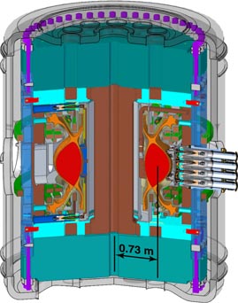
Figure 1. ADX is a compact, high power density, high-field (6.5 T) tokamak with demountable toroidal field magnets and internal poloidal field coils. It is designed to test advanced divertor and innovative RF current drive and heating techniques at performance parameters required for a fusion power plant while simultaneously attaining core plasma regimes prototypical of a reactor.
Download figure:
Standard image High-resolution imageSince the total fusion power output from a tokamak scales as (βN/q)2R3B4 (βN—pressure normalized to the Troyon limit [10], q—safety factor, R—major radius, B—magnetic field strength) while overall cost scales roughly as magnetic stored energy, R3B2, tokamaks that utilize very high magnetic field strengths have tremendous economic advantage. Recently, an exciting new high-field, compact design concept has been proposed [11], the 'affordable, robust, compact' (ARC) fusion pilot plant. This device is similar in size to the Joint European Torus (JET), but produces 270 MW net electrical power output. The concept uses high magnetic field (9.25 T on axis) to attain high power density in a compact size. Consequently, unlike other approaches, it does not need to push tokamak plasma physics performance parameters (e.g., confinement, beta, proximity to operational limits) beyond what has already been achieved simultaneously in present devices. Key features of the ARC concept are: high-temperature, high-field, demountable superconducting magnets; immersion blankets; and the use of LHCD and ICRF actuators located on the high-magnetic-field side for efficient current drive, current profile control and heating. With the possibility of ARC in mind, critical-path research on the road to fusion electricity shifts away from seeking further enhancements in core plasma performance at moderate magnetic field (e.g., increased beta) and more towards finding viable physics/engineering solutions for the support systems of the fusion power plant—power/particle handling, RF current drive systems, magnet systems, and blanket—while at the same time demonstrating good core plasma confinement.
ADX is prototypical in many ways for an ARC-like reactor concept, particularly in terms of its operation at high absolute plasma pressure but moderate plasma beta; it is a compact, high power density, high-field tokamak (6.5 T with possible upgrade to 8 T) with demountable toroidal field magnets. Nevertheless, innovative solutions demonstrated in ADX would qualify them for essentially any tokamak-based power plant scheme. Fusion power plants must all achieve high neutron wall loading at high fusion power gain. As a result, the power flux density flowing through their boundaries is generically the same. Divertor and RF systems must therefore operate at similar absolute plasma parameters (density, magnetic field, temperature) and attain similar levels of engineering performance (heat flux, erosion handling).
3. Mission
The mission for ADX can be stated succinctly: identify, develop and demonstrate plasma exhaust, PMI and RF current drive/heating solutions at FNSF/FPP/DEMO parameters that are compatible with obtaining high confinement core plasmas, and that scale to long pulse plasma operation. To this end, ADX targets the five milestones listed below. These address critical 'gaps' that must be bridged before proceeding to FNSF/FPP/DEMO, as outlined in planning documents and roadmaps from the US Office of Fusion Energy Science [12] and the European Fusion Development Agreement [13] (now reorganized as EUROfusion).
Milestones targeted by ADX
- 1Demonstrate robust divertor power handling solutions at boundary plasma parameters (heat fluxes, plasma pressures and PMI flux densities) approaching FNSF/FPP/DEMO conditions, which scale to long-pulse operation.
- 2Demonstrate nearly complete suppression of divertor material erosion, sufficient to sustain divertor lifetime for ∼5 × 10⁷ s of plasma exposure at FNSF/FPP/DEMO parameters.
- 3Achieve the above two goals while demonstrating a level of core and pedestal plasma performance that projects favourably to a fusion power plant and in physics regimes that are prototypical.
- 4Demonstrate efficient radio frequency current drive and heating techniques that minimize PMIs, scale to long-pulse operation and project to effective current profile control.
- 5Determine high-temperature PMI response of reactor-relevant plasma-facing material candidates, such as tungsten and liquid metals, in an integrated tokamak environment, assessing issues of material erosion, damage, material migration and fuel retention at reactor-level performance parameters.
4. Motivation: solutions needed for power exhaust and material erosion (milestone #1, 2 and 3)
4.1. Challenges
The challenges that face a power-producing tokamak reactor can be best appreciated by considering the challenges that face ITER. In ITER's planned baseline scenario [15], its QDT = 10 burning core with 33% input power radiated would send 100 MW of heat exhaust via a narrow channel (with an assumed width, λq ∼ 5 mm, at outer midplane) towards its tungsten, vertical target plate divertor [16]—the most advanced divertor concept at the time of ITER's design, pioneered by Alcator C-Mod [17]. Assuming that disruptions can be avoided/mitigated and ELMs can be reduced or eliminated [16], this steady heat flow would be accommodated (i.e., reduced to less than 10 MW m−2 surface heat flux) by producing a 'partially detached' divertor state, in which 70% of the scrape-off-layer (SOL) power is radiated, facilitated by impurity seeding (Ar, Ne, N). The projected value heat flux channel width (λq ∼ 5 mm) was highly uncertain, however, and a coordinated multi-machine investigation was initiated in 2010 to develop an empirical scaling law to ITER conditions. The results of this investigation do not support the assumption of λq ∼ 5 mm. In fact, the results clearly indicate [14] that λq in low-recycling H-modes is independent of machine size and scales inversely with poloidal magnetic field strength at the outer midplane, projecting to a λq in ITER that is the same as C-Mod, λq ∼ 1 mm (figure 2). Moreover, from simple geometry, this result means that the heat flux flowing along field lines into the divertor scales as q∥ ∼ PSOLB/R,7 with PSOL being the total power entering the SOL. This is a serious challenge for successful ITER operation; experiments are now examining if this scaling for upstream λq holds true when the divertor is in a partially detached regime.
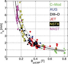
Figure 2. Results from multi-machine scaling [14] indicate that the heat-channel width, λq, is independent of machine size and scales inverse with poloidal magnetic field strength. This projects to λq ∼ 1 mm for ITER, having the same poloidal field strength as C-Mod. Reprinted from [14]. Copyright 2011 IOP Publishing.
Download figure:
Standard image High-resolution imageA fallback position is to increase core radiation but at the penalty of degrading confinement. As shown in figure 3, experiments suggest that in order to maintain H98 above 1, PSOL must exceed the L–H power threshold, which is expected to be PLH ∼ 50 MW for ITER. This implies that a doubling of the core radiated power fraction from 33% to 66% is possible, but not more. A factor of 5 reduction in 'planned λq' means that q∥ at the entrance to the divertor may be 2.5 times the value originally anticipated.
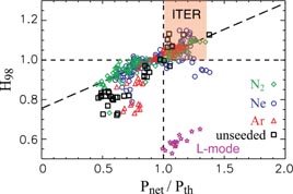
Figure 3. Good core confinement (H98 >1) requires SOL power (PSOL ∼ PNET) above the L–H power threshold value (Pth) [18]. This places a restriction on core radiation and sets a minimum value PSOL that the divertor needs to handle, PSOL ∼ Pth ∼ 50 MW for ITER. Reprinted from [18]. Copyright 2011 AIP Publishing LLC.
Download figure:
Standard image High-resolution imageExperiments are presently using a combination of core and divertor seeding to explore the maximum PSOLB/R that a conventional high-Z (W or Mo) vertical target plate can handle while maintaining good core confinement. ASDEX-Upgrade has obtained PSOLB/R ∼ 18 [MW-T/m] [19] while C-Mod has obtained PSOLB/R ∼ 25 [18]. Although experiments are continuing to optimize the tradeoff between power handling and confinement, this parameter is significantly short of PLHB/R ∼ 45 required for ITER. As illustrated graphically in figure 4, the requirements for a DEMO (as embodied in ARIES ACT1 and ACT2 concepts [20]) or a FPP (ARC concept [11]) are much worse, even if large core radiation fractions (∼85%) are assumed such that these devices operate with PSOL ∼ PLH—a situation potentially at odds with avoiding fuel dilution and maintaining adequate core confinement. If ITER finds that the empirical projection for λq is somehow wrong and that λq is more in line with originally planned values, then the power handling challenge for ACT1/ACT2/ARC is still a factor of 2 to 3 times worse than ITER, simply because plasma exhaust power densities are 2 to 3 times higher.
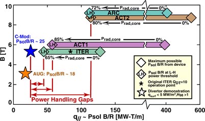
Figure 4. C-Mod and AUG have demonstrated H98 > 1 with acceptable divertor surface power densities (i.e. <5 MW m−2) at the indicated values of B and PSOLB/R (stars). Experiments are continuing to optimize performance, but these parameters are a factor of ∼2 away from ITER and very far from accommodating FPP/DEMOs as represented by ARIES ACT1, ACT2 [12] and ARC [6].
Download figure:
Standard image High-resolution image4.2. Divertor erosion gap
Long pulse length (∼5 × 10⁷ s) operation of FNSF/FPP/DEMO imposes an additional challenge on divertor operation, not encountered in present experiments or ITER—much more severe than the divertor power handling challenge: nearly complete suppression of material erosion and PMI damage at divertor target plates is required [21]. Steady-state heat removal of qs ∼ 10 MW m−2 on high-temperature solid targets requires thin refractory (W) plasma-facing components, on the order of ∼5 mm thick [22]. This restricts the allowed net surface erosion rate to be less than 1 mm per year, or a net W erosion flux of ΓW ∼ 1.5 × 10¹⁸ m−2 s−1. At an electron temperature of 6 eV, plasma surface heat flux at qs ∼ 10 MW m−2 corresponds to a bombarding ion flux of Γion ∼ 1.5 × 1024 m−2 s−1. Thus net W erosion yield per incident ion must be suppressed to 10−6, even in the presence of impurity ions (Ar, Ne, N) used for seeding. Measurements [23] and models find W sputtering yields in the divertor to be on the order of 10−4 for typical impurity concentrations—a performance 'gap' of a factor of 100. It was thought that prompt-redeposition physics would help—sputtered W ionizing within a Larmor orbit that carries it back to the plate. But deposited material is not tightly bound to the bulk and becomes mixed with impurities; subsequent sputtering yields can be 10 times that of the original bulk material [24]. Helium ion bombardment at energies exceeding 20 eV also damages tungsten via implantation and, among other things, leads to the formation of 'nano-tendrils' at elevated surface temperatures [25]—a new mechanism to destroy a solid material surface. Thus, the only solution—apart from using self-annealing, liquid metal targets—is to operate in regimes in which the divertor plasma is fully detached, i.e., a state in which electron temperatures are well below 5 eV, impurity ion impact energies are below sputtering and damage thresholds, ion–neutral collisions remove plasma momentum, radiation/neutrals carry heat to surfaces and ion fluxes to target plates drop by more than two orders of magnitude. Unfortunately, present experiments (with conventional divertors) have not been able to attain a fully detached divertor (i.e., an order of magnitude reduction in ion flux at all divertor target surfaces) while at the same time maintaining good core energy confinement. The highest values of q∥ ∼ PSOLB/R that have been attained with acceptable heat loads and good confinement are with partially detached divertors. The difficulty in extending the detachment region over the entire divertor target comes from the tendency of the 'thermal front' to intrude into the confined plasma by forming an 'X-point MARFE' [26], thereby cooling the pedestal region and degrading core performance. Just as in the case of heat flux control, conventional divertors seem to impose an unavoidable tradeoff between maintaining good core confinement and protecting divertor targets from destruction. While specific details of the detachment behaviour differ among experiments (e.g., radiative species mix, divertor target plate material and orientation, extent of detachment front), the overall behaviour is the same. Divertor solutions that can decouple the detachment response from the core plasma response have not yet been attained—let alone demonstrated at the power and particle flux densities required for a DEMO.
4.3. Potential solutions
Advanced magnetic divertors, such as the X-divertor (XD [27]), snowflake (SF [28]), Super-X divertor (SXD [29]) and X-point target divertor (XPT [9]), were conceived to address the extreme power exhaust challenge via a number of techniques (figure 5). Proof-of-principle experiments performed at low and moderate power fluxes are finding that the SF concept behaves roughly as anticipated: surface heat flux is reduced due to flux expansion, increased radiation and convective heat flows [30–34]. Further experiments are needed to compare performance improvement (i.e., heat flux reduction) of SF and XD concepts relative to an ITER-like vertical target plate divertor, which employs flux expansion via target tilt angle rather than poloidal field reduction.

Figure 5. Advanced divertors seek to spread the narrow incident heat channel, λq, onto a larger 'wetted area' by a combination of 'flux expansion' via target tilt and poloidal magnetic field coils, enhanced turbulence, radiation and interaction with neutrals. XPT divertor concept is shown at upper-right. This and the SXD place divertor target plates at large major radius in a remote divertor chamber. The ∼1/R variation of the parallel heat flux into the detachment zone (represented as an expanding flux tube in the graphic above) helps to stabilize the location of the thermal front—keeping it in the divertor volume. Long-legged, highly baffled divertors may also facilitate the use of liquid metal targets. Note: the pictures shown here and in figure 7 are 'artist's views' of the XPT concept; detailed modelling and optimization of this concept and others for ADX remain to be performed.
Download figure:
Standard image High-resolution imageSXD and XPT concepts are long-legged divertors that attempt to solve the power handling challenge by placing targets at large major radius in a separate divertor chamber. This yields a corresponding reduction in q∥ by total flux expansion, i.e., B ∼ 1/R. The XPT concept (shown in figure 5) starts with the SXD idea, but places an X-point in a divertor chamber as a 'virtual target', intercepting flux tubes that carry the highest q∥. The local X-point in the divertor can be a first order or higher order null, taking advantage of a 'churning mode' identified for snowflake topologies [35] to activate multiple legs—a 'snowflake target divertor'. Most importantly, the XPT may produce a stable 'X-point MARFE' that is localized to the divertor chamber, ideally equidistance from divertor chamber walls, to spread heat uniformly over a large surface area. This is the ultimate goal for any advanced magnetic divertor—produce a fully detached divertor, reduce surface heat loads and erosion to acceptable levels while at the same time maintaining high core plasma confinement by avoiding pedestal cooling.
Analysis shows [36] that the position of the detachment 'thermal front' (i.e., a region where the temperature drops abruptly along a field line) is set by the balance between parallel heat inflow at the front's leading edge, q∥, and the front's volumetric losses via a variety of means: intrinsic impurity radiation, extrinsic (seeded) impurity radiation, hydrogenic radiation, and charge exchange neutrals. A thermal front can fully accommodate the q∥ up to maximum value, q∥max, which, for a given impurity species radiator, is set by the plasma pressure and the impurity fraction. The lifetime of the impurity in the plasma also plays a role, affecting its average charge state and thus radiation level. When q∥ exceeds q∥max, the front gets 'pushed back' towards the target plate and/or the front gets 'burned though', i.e., the abrupt temperature drop along field lines is eliminated. Thus by placing the target plate or X-point target at large major radii, the detachment front may be stabilized; if the front attempts to move 'upstream' towards the confined plasma, it encounters a region of higher q∥ which arrests its motion (bottom panel in figure 5). For these reasons, the SXD and XPT concepts are the ones targeted first for testing in ADX, which sets the initial poloidal field coil design. MAST is scheduled to perform proof-of-principle tests of the SXD concept for the first time in 2016/17 [37]. Although these tests will be at low power density, they should provide valuable information.
Liquid metal targets, despite their added complexity, may turn out to be the only means of handling the highly focused exhaust from a fusion reactor, as well as tolerating heat transients (ELMs, disruptions). Long-leg, highly baffled divertor geometries can work synergistically with liquid metal target concepts, which employ vapour shielding physics, e.g., as addressed in [38]. By operating divertor surfaces at temperatures lower than the main chamber walls, liquid metals and impurities may be controlled by preferential condensation in the divertor. A successful liquid metal target technology would also eliminate the need to operate with a fully detached divertor; the self-annealing surface would accommodate the bombarding ion flux without damage. As discussed in section 7.2, ADX will employ a modular vacuum vessel design which would enable the development and implementation of liquid metal divertor target ideas. The lower, outer divertor leg would be a natural test bed. Implementation of successful liquid metal target options in the upper, outer leg may require up–down asymmetric divertor magnetic topologies/geometries, different from that shown in figures 7 and 13. The ability to modify the vacuum vessel to accommodate such possibilities is an important asset.
The above considerations strongly motivate the need for an ADX and define its requirements: ADX must not only have the power density and magnetic field strength to simulate reactor-level conditions, it must also have the flexibility in its design to test the most promising ideas for solving heat flux and erosion challenges.
4.4. Power and magnetic field requirements for an ADX
The electron temperature at the divertor target plate in a reactor will be in the range of ∼5 eV or less—this is dictated by atomic physics and the requirement that partial or full divertor detachment be attained. Stangeby and Leonard [21] argue that divertor target plate conditions of Te,div ∼ 5 eV and ndiv > 1021 m−3 must be attained in order to avoid rapid destruction of the divertor targets in a reactor by sputtering erosion. Having fixed the divertor electron temperature, the plasma density (and thus plasma pressure) in the divertor is determined by q∥—either by the requirement of conducting q∥ through the plasma sheath or by the requirement of dissipating q∥ by impurity radiation in a thermal front [36]. In order to match key dimensionless parameters that control PMI physics (e.g., λdebye/λion, ρz/λion, with λdebye = Debye length, λion = ionization mean free path, ρz = impurity Larmor radius), Te,div, ndiv and B must be made identical to a reactor [2]. Taken together, this means that B and q∥ combined with magnetic/target plate geometry must be made identical to a reactor. Consistent with this picture is the requirement that reactor-level B−fields are needed to produce reactor-level plasma pressures in the boundary plasma, due to beta limits associated with the edge plasma pedestal [39]. As discussed by Hutchinson and Vlases [3], by matching B, n and q∥ of a reactor it is also possible, at least in principle, to perform an approximate 'divertor similarity experiment' in which five key scale parameters (Te, ν* = Ld/λei, Δd/λ0, ρi/Δd and β, with Ld = divertor field line length, λei = electron–ion collisional mean free path, Δd = SOL thickness, λ0 = neutral mean free path, ρi = ion Larmor radius, β = 2μ0nT/B2) are identical to those of a reactor. The poloidal flux expansion and divertor leg length could be adjusted to do this. In any case, the overall message is clear: matching absolute reactor divertor parameters (B, q∥, ndiv, Te,div) is necessary to study reactor-relevant physics regimes. Based on the recent multi-machine empirical scaling of parallel heat flux [14], the parallel heat flux scales as q∥ ∼ PSOLB/R. This means that B, n and PSOLB/R in an ADX should be made similar to that in a reactor. From figure 6, it is clear that a compact, high-field tokamak is the natural choice for an ADX—it is the way to perform meaningful tests of advanced divertor prototypes without constructing a full-scale reactor; it removes the uncertainty and risk in trying to extrapolate divertor performance from extremely complex and uncertain computational models, developed and tested in regimes that are far from those expected in a reactor.

Figure 6. B and PSOLB/R for world tokamaks. (Arrows for EAST and KSTAR account for planned upgrades.) In order to simulate divertor conditions of a reactor, both B and PSOLB/R must be matched. A compact, high-field tokamak is the most cost-effective way to achieve this, as shown by Alcator C-Mod attaining parameters close to the range of ITER, ACT1 ACT2 and ARC. A similarly constructed ADX can push to high PSOL values at small cost, because of its small size.
Download figure:
Standard image High-resolution image5. Motivation: low-PMI RF actuators; efficient current drive, heating needed (milestone #4)
5.1. Challenges
It is recognized that RF current drive and heating technologies must evolve into primary actuators for fusion reactors, replacing the roles that neutral beams now play in most devices. As stated in a 2007 US DoE [12] report (addressing 'gap G-7' on page 190): 'The auxiliary systems typically used in current experiments, while extremely useful tools, are not generally suitable for a reactor. RF schemes are the most likely systems to be used and will require significant research to achieve the levels of reliability and predictability that are required.' For ICRF antennas and LHCD launchers, it means placing these actuators close to the plasma, where the challenge of efficient power coupling competes with minimizing PMI. For long pulse operation, the lifetime of the launcher will be determined by PMI. But most critically, the current drive system's efficiency (wall plug to plasma) and ability for current profile control are what matter the most; the viability of the tokamak concept as a steady-state fusion reactor depends on them. For this reason, LHCD is considered as a first-choice actuator; it is recognized as the most efficient RF current drive scheme. Unlike electron cyclotron current drive (ECCD) [42], the RF waves impart parallel momentum directly to electrons. On the other hand, ECCD may be a fallback option should the LHCD launcher PMI challenge prove impossible to solve.
5.2. Potential solutions: HFS launched ICRF and LHCD
5.2.1. Plasma–material interaction
From a PMI perspective, locating ICRF and LHCD antenna structures on the HFS of the torus with double-null magnetic equilibria is a potential game-changer (figure 7), yet it has never been exploited. Experiments clearly show that: (1) a low heat flux, quiescent boundary layer naturally forms on the HFS in double-null plasmas with: no heat/particle pulses reaching there from ELMs [45], essentially zero fluctuation-induced fluxes [40] and no 'blobs' (figure 8); (2) local plasma recycling fluxes are low, which minimizes neutral pressures in the vicinity of antenna/waveguide structures, leading to improved RF voltage handling [46]; (3) the flux of energetic ion orbit loss on the HFS is virtually non-existent; (4) energetic particles formed by RF fields have drift orbits that move away from the launch structure; (5) there is no impact from runaway electrons at this location; (6) any impurity ions that are produced by PMI on RF antenna structures would likely be very well screened, based on results from impurity transport experiments [43] (figure 9); (7) because of the steep profiles, the local density at HFS launch structures can be precisely controlled by adjusting the upper/lower X-point flux balance [47] and/or distance from the last-closed flux surface (LCFS) to launcher (figure 8).
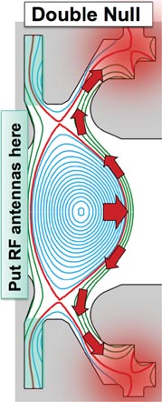
Figure 7. RF antennas can take advantage of the low-PMI, 'quiescent' SOL that forms on the HFS in double-null plasmas and the dominant power exhaust through the low-field side (LFS) SOL (represented by red arrows).
Download figure:
Standard image High-resolution image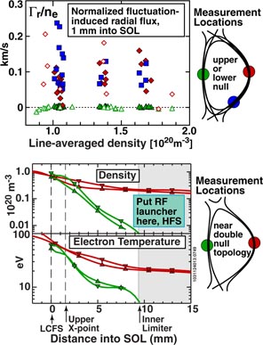
Figure 8. Fluctuation-induced radial particle fluxes are essentially zero on the HFS, independent of magnetic X-point topology (top panel; data are shown from discharges described in [40]; open and closed data points are from different run campaigns). As a result, in near double-null topologies, the HFS density and temperature profiles are extremely steep; conditions at local launch structures can be controlled externally by variation of X-point flux balance and/or distance between LCFS and launcher (bottom panel; data shown from discharges described in [41]).
Download figure:
Standard image High-resolution image
Figure 9. Measurements of impurity penetration factor (i.e., ratio of total number of core impurity ions to local injection rate) for N2 and CH4 impurity gases as a function of poloidal location in Alcator C-Mod. Data are from experiments described in [43]. Impurities injected from the HFS (poloidal angle = 180°) have remarkably low penetration factors—even lower than impurities injected into the divertor. In contrast, impurities injected on the LFS have penetration factors that are ∼10 times greater. Therefore, just from an impurity screening perspective alone, the HFS is the best location to put RF antennas; an order of magnitude reduction in core impurity concentration might be achieved for the same antenna-induced impurity source rate. The mechanism for enhanced impurity penetration on the LFS is thought to be caused by interchange turbulence—blobby transport (e.g. [44]) that is absent on the high-field SOL—in which clean, high density plasma exchanges its position with impure low density plasma. Experimental verification of this inward impurity transport mechanism on the low-field SOL has yet to be performed, however.
Download figure:
Standard image High-resolution imageOne might ask: can antennas be placed on the inner wall of a tokamak? Is there enough space? The answer is yes [11, 48]. The size of antenna/waveguide structures is dictated by RF wavelengths—not machine size—and these structures are already employed in compact tokamaks (e.g., C-Mod). Thus, inside-launch RF antennas can be designed to fit into the blanket of an FNSF/FPP/DEMO-sized device without compromising neutron shielding requirements while at the same time tapping into the local blanket cooling system. The RF 'plumbing' for an inside-launch LHCD system would not be much different than for coolant pipes in terms of size and robustness—metal waveguides, with no dielectrics, insulators or windows placed in the neutron environment. Potential designs for HFS LHCD and ICRF launchers in ADX are discussed in sections 7.3 and 7.4.
5.2.2. RF wave physics
HFS launch is a potential game-changer for LHCD wave physics, resulting in high efficiency current drive with profile control to mid minor radius [49–52] (figure 10). The increased magnetic field at this location enables waves to be launched with lower n∥, penetrating deeper into the plasma before damping. This alone can lead to significant increases in current drive efficiency—more than 60% in the Vulcan study [49]. By launching off midplane near a region of reduced poloidal field (i.e., near an X-point), ray trajectories can also be 'steered' to propagate directly towards the plasma centre. These improvements have been exploited in both the Vulcan and ARC [11] designs. In fact, the favourable LHCD physics of high-field launch is central to making these concepts viable.

Figure 10. Accessibility results from a ray tracing/Fokker–Planck LHCD study [51], used to examine the benefits of HFS launch for an FNSF-AT [53] test case. Accessibility on the HFS allows low n∥ rays to access r/a ∼ 0.6. Driven current profiles are much broader and can be tailored by launcher design. LHCD efficiency is improved by 40% to ηCD ∼ 3.4 × 10¹⁹ A W−1 m−2.
Download figure:
Standard image High-resolution imageRecent LHCD experiments in C-Mod have uncovered a clear, direct correlation between the local plasma density in the SOL and the onset of parasitic wave energy loss mechanisms (collisional damping [54], parametric decay instabilities [55, 56], wave scattering [57, 58] and full wave effects [59]). On the LFS, the SOL density profiles are broad, and, due to the rapid cross-field transport mechanisms that take place there, the density in the local SOL and at the launcher mouth is not controlled; the launcher must be placed very far from the LCFS to avoid PMI, particularly in a reactor. In contrast, the sharp density falloff in the HFS SOL (figure 8) allows the launcher to be located very close to the LCFS. This, combined with the ability for precise density control at the mouth may allow these SOL loss mechanisms to be virtually eliminated. Wave scattering from density blobs would also be non-existent.
HFS launch also leads to beneficial ICRF fast-wave physics [52]. With HFS launch, fast waves mode convert directly to ion Bernstein waves (IBW) and ion cyclotron waves (ICW), leading to strong single-pass absorption and direct electron heating. This avoids the generation of energetic ion tails and possible destabilization of energetic particle populations (including fusion alphas in a reactor), completely suppressing this mechanism for ion-induced sputtering of first-wall components.
In summary, we note that there is excellent three-way synergy among double-null plasmas, advanced divertor solutions and inside-launch RF systems—all working to focus the PMI onto systems that can handle it and away from systems that cannot—and at the same time providing unprecedented improvements in current drive and heating wave physics. These ground-breaking ideas, and the means to test and exploit them, are primary foci of the ADX conceptual design.
6. Critical need for FPP/DEMO: assess high-temperature PMI response (milestone #5)
In order to attain good thermal efficiency, fusion power plants will need to operate with high-temperature plasma-facing components [22]: divertor target plate coolant temperatures of ∼600 °C and surface temperatures well exceeding 1000 °C. This is a situation not yet experienced in present experiments (nor will it be in ITER) with consequences for tokamak PMI physics—affecting PMI material response to plasma exposure (figure 11), fuel retention and perhaps synergies with plasma operation. It is important therefore to find solutions that project towards applicability in a high material temperature environment. Progress can be made in ADX by providing for divertor targets and liquid metal concepts to be operated at high temperatures and to implement state-of-the-art in situ [60] and ex situ PMI diagnostics to assess material responses. Extensive R&D work for Alcator C-Mod has produced a complete engineering design for a toroidally-continuous, heated tungsten outer divertor (600 °C bulk temperature) [61], employing compact embedded heaters, radiation thermal shields and mechanical linkages that accommodate thermal expansion. Similar techniques can be used to produce heated test modules and/or full toroidal divertor targets in ADX.
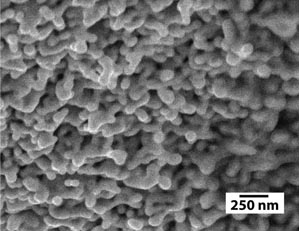
Figure 11. Tungsten nano-tendrils formed at high material temperature by helium plasma exposure in the Alcator C-Mod divertor. Experimental conditions are described in [25].
Download figure:
Standard image High-resolution image7. ADX conceptual design
An initial design concept for ADX is shown in figure 12. This concept employs the demountable, high-field copper magnet technology developed for Alcator C-Mod [62] and makes use of existing infrastructure presently supporting the C-Mod facility at MIT: experimental cell, power supplies and control systems, high power switching gear, a 225 MVA motor-generator/flywheel, advanced computing and data acquisition network, 8 MW source power 50–80 MHz ICRF system (upgraded to 10 MW and 90–120 MHz for ADX), 4 MW source power 4.6 GHz lower hybrid system and extensive plasma diagnostic systems. ECRH may also be considered as an upgrade option for ADX, but is not included in this initial design. As a design starting point, the overall footprint of ADX is kept the same as C-Mod's, allowing the upper and lower 'domes' and TF 'wedge plates' to be reused. The vertical height of the toroidal field coils, central solenoid and outer support cylinder is increased by approximately 0.5 m, providing space for a vertically-extended, load-bearing vacuum vessel that contains the poloidal field coils needed for a variety of advanced magnetic divertor configurations. In order to make more room for HFS RF systems, the plasma major radius is increased from 0.67 to 0.73 m, minor radius decreased from 0.22 to 0.2 m, while vertical elongation and overall plasma shaping are held approximately the same as in C-Mod.

Figure 12. Initial design concept and targeted performance parameters for ADX. ADX builds on the high-field, demountable toroidal field magnet technology and RF systems developed for the Alcator programme.
Download figure:
Standard image High-resolution image7.1. Divertor
Results from a magnetic equilibrium scoping study, examining the ability to produce different divertor configurations using a fixed poloidal field coil set, are shown in figure 13. The cases shown correspond to a 1.0 MA, 5.4 T discharge. ADX is expected to have a similar power exhaust channel width as Alcator C-Mod, in the range of 1 to 3 mm. The first 10 mm of the SOL (highlighted in orange) is accommodated by envisioned divertor topologies. A set of 10 poloidal field coils (5 upper and 5 lower) is added to the C-Mod coil set to produce the geometries shown. The arrangement of coils shown provides for coaxial feed line connections to external power systems, but a wide range of other configurations and divertor leg shapes is also possible. Maximum currents in the poloidal field coils do not exceed typical values for a comparable C-Mod discharge. Magnetic forces are also similar and readily accommodated by the rigid vacuum vessel and mechanical supports placed at regular intervals in toroidal angle—the technique presently used successfully in Alcator C-Mod.
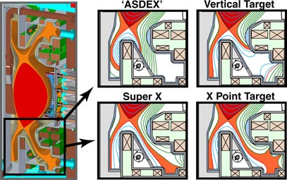
Figure 13. Initial scoping of divertor configuration flexibility using a fixed poloidal field coil set. ADX would also be capable of testing different divertor coil arrangements and vacuum geometries, including liquid metal target options. Magnetic equilibria shown are generated using ACCOME [63] with coil currents similar to those operated in Alcator C-Mod. The first 10 mm of the SOL mapped to the outer midplane is highlighted in orange.
Download figure:
Standard image High-resolution imageCryopumps are incorporated into the outer leg divertor chambers (small circle under the outer divertor leg, shown in figure 13), although their optimal placement and the optimum shape of the chambers has not yet been determined. It is envisioned that full or partial loop cryopumps would be used, employing an efficient 'pot' design developed for C-Mod [64], which does not require a flowing helium loop. Diagnosis of the divertor plasma, boundary plasma, and PMI at the divertor surfaces in the different configurations is crucial. Not shown are embedded gas feeds and divertor instrumentation that will be required to control and monitor divertor conditions. Optical access to the divertor volume is restricted compared to present-day tokamaks and will therefore require special radial ports that are included in the conceptual design.
One might ask: 'These poloidal field coil arrangements look like they will not have adequate room for neutron shielding. How can divertors like these be used in a fusion reactor?' A D–T neutron environment certainly places severe constraints on the placement of the coils and the design choices. Lackner and Zohm [65] considered the consequences of locating poloidal field coils far from the plasma and found that the coil currents required to produce a snowflake topology may become prohibitively high. But ADX is not constrained in these ways. Rather, ADX addresses a more fundamental question: given nearly complete freedom in coil arrangement, does there exist an advanced divertor scheme that can handle a fusion reactor's power exhaust density? Once having identified a successful scheme, there are several approaches that might be taken to implement it in a D–T environment. The first is to employ a coil arrangement that does have adequate shielding while retaining the desired physics effect. Kotschenreuther et al have found such schemes for the Super-X divertor [66]. The second is to employ non-superconducting poloidal field coils in critical locations that can withstand enhanced neutron damage while having sufficient, albeit reduced, operational lifetime. For example, single-turn copper control coils were proposed in the ARC concept [11]. These would survive for lifetimes of ∼2 years in the neutron environment and be replaced with the vacuum vessel. The use of a demountable, superconducting toroidal field magnet makes this possible. A combination of both schemes would probably be employed in a reactor—a set of radiation-shielded long-life superconducting coils to provide basic shaping in conjunction with replaceable shorter-lifetime coils that produce the fine structure and control of the divertor leg topology. In this sense, the development of demountable superconducting magnets and replaceable, radiation-tolerant divertor coils goes hand-in-hand with the development of advanced magnetic divertor schemes that can handle a reactor's power exhaust power density.
7.2. Demountable copper TF magnet
The demountable toroidal field magnet, with external superstructure, is an important feature of the ADX design, as well as being highly desirable for a reactor; (1) it facilitates the construction and maintenance of a very high field tokamak with internal poloidal field coils and (2) it serves as a 'shell' that can accommodate different vacuum vessel designs, poloidal field coil sets and/or divertor target components, facilitating relatively nimble configuration modifications. With the exception of RF launcher and antenna structures, it is envisioned that all internal vessel components (first-wall and divertor tiles, diagnostics, RF feeds, cryopumps) would be installed and tested off-line during assembly of an integrated vacuum vessel/poloidal field coil unit that is composed of modular sections (figure 14). One can also envision performing experiments on a specific divertor and/or RF concept in ADX while at the same time preparing new/modified vacuum vessel modules off-line, either on-site or off-site by collaborating institutions. This would be particularly valuable for implementing liquid metal divertor targets, where extensive off-line tests of the liquid handling system may be required. It should be noted that as part of C-Mod's routine maintenance programme, the sliding joints of the toroidal field magnets are inspected at regular intervals, requiring full disassembly of the superstructure—lifting the vacuum vessel with embedded coils to a temporary work location. The approach for ADX would be similar. A newly prepared vacuum vessel would be swapped out with the old one, or subsections of the modular vacuum vessel could be upgraded/replaced as needed to support the experimental programme.
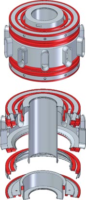
Figure 14. The ADX vacuum vessel (top) would be constructed from separate sections (bottom) that accommodate the advanced divertor poloidal field coil set (red). It is envisioned that divertor sections would be customized with specialized target materials and embedded diagnostics as needed to test different concepts, including heated and liquid metal targets.
Download figure:
Standard image High-resolution image7.3. Pulse length
Using cryogenically cooled copper magnetics (LN2), the overall plasma pulse length in ADX is projected to be ∼3 s at full performance and longer (∼5 s) at modestly reduced field and current. Based on preliminary estimates, the existing 225 MVA motor-generator at the PSFC combined with primary source power would allow 6.5 T, 1.5 MA operation for a 1 s flat-top. However, since the magnet systems and overall superstructure are based on the Alcator C-Mod design, it would support 8 T, 2 MA operation with an appropriate power systems upgrade.
One might ask: 'how is a pulse length of ∼3 s with ∼1 s flat-top relevant for developing steady-state power handling, PMI and RF solutions?' The answer is that a ∼ 3 or even ∼1 s pulse (τpulse) is actually ideal for ADX's mission. It is much longer than plasma energy (τE) and particle (τp) confinement time scales as well as PMI (τPMI) and current relaxation (τCR) time scales [48], but it is shorter than first-wall component thermal equilibration times (τthermal). Solutions identified in ADX can therefore be projected with confidence toward steady-state operation:
- τpulse ≫ τE, τp—steady power and particle exhaust is established in core and divertor; divertor performance, control methods, impurity behaviour, core performance can be assessed.
- τpulse ≫ τPMI—steady ion fluxes and material erosion/redeposition fluxes are established; erosion and redeposition, ion-induced damage rates (divertor and RF actuators) can be assessed. State-of-the art, in situ material surface diagnostics (e.g., [60]) can be employed to determine material response between discharges and to project their viability for long-pulse operation.
- τpulse ≫ τCR—fully relaxed current profiles are established; non-inductive current drive and current profile control for enhanced core plasma confinement scenarios can be assessed.
- τpulse < τthermal—first-wall components are 'inertially-cooled'. In this respect, ADX would not simulate steady-state reactor conditions. But τpulse < τthermal provides important practical and economic advantages: (1) surface heat fluxes of ∼40 MW m−2 (∼1 s exposure) can be accommodated by refractory materials without surface melt damage; (2) the high cost and complexity of steady-state cooling is avoided, both for first-wall components and for RF systems; (3) simplified schemes for testing liquid metal divertor target ideas can be employed.
As stated in section 3, ADX's central mission is to identify reactor-relevant plasma physics solutions that extrapolate to steady state. The proposed pulse length is ideal for this purpose. A top priority for magnetic fusion energy development is to demonstrate solutions for divertor power and erosion handling that can operate successfully on these time scales and at the absolute performance parameters that are required (power exhaust density, magnetic field strength, plasma pressures) while at the same time producing excellent core plasma performance. Lacking that demonstration, any investment in next-step steady-state experiments carries a very high risk.
ADX would not address effects related to thermal equilibrated walls and the 'working' of material from long-time plasma (or neutron) exposure, e.g., film growth and/or surface modifications at very large fluences. In principle, high power, linear plasma-material test devices can be used to explore key aspects of this long-time material 'working' behaviour, once viable divertor solutions are found—i.e., the magnetic geometry, compatible materials, control schemes needed—and the resultant plasma parameters at the target plates (particle and energy fluxes, plasma densities and temperatures) are characterized in ADX.
Finally, while ADX would readily identify core plasma regimes that are time stationary (or not), over its 1–3 s pulse length, ADX would not fully resolve very long-time core plasma evolution (i.e., exceeding ∼10 to ∼30 energy confinement times), such as might occur from high-Z impurity accumulation inside an internal transport barrier.
7.4. Divertor plasma parameters
The parameters shown in figures 6, 15 and 16 highlight ADX's unique ability to test divertor solutions at reactor-level conditions. As discussed in section 4.4, it is necessary to match absolute values of both B and q∥ of a reactor in order to reproduce the divertor and PMI physics regimes of a reactor. Based on a multi-machine database [14], the parameter PSOLB/R is the figure-of-merit that determines the relative magnitude of the 'upstream' q∥ in the tokamak SOL. ADX's high field, high power and small major radius push PSOL,MAXB/R, λq and q∥ well beyond what is available from current or other planned experimental tokamaks, accessing values that are comparable to and go beyond ITER (see figure 15, and top panel in figure 16).

Figure 15. Comparison of power exhaust parameters for current and proposed tokamaks. For Alcator C-Mod and ADX, cases for two different magnetic fields and currents are shown, separated by colons. (1)—total source power. The range shown accounts for planned or proposed upgrades. In practice, the total input power is restricted by operational beta limits and compatibility with operation at maximum field, which is not accounted for here; (2)—power density through LCFS, based on total source power and no core radiation; (3)—power through LCFS divided by major radius, based on total source power and no core radiation; (4)—figure of merit for upstream parallel heat flux density (q∥), based on λq scaling as 1/Bθ; (5)—figure of merit for upstream poloidal heat flux density (qθ), based on λq scaling as 1/Bθ; (6)—heat flux channel width normalized to that in ADX (6.5 T), based on multi-machine scaling for λq [14]; (7)—SOL parallel heat flux normalized to that in ADX, based on multi-machine scaling; (8)—heat flux channel width expansion factor required to accommodate total source power while attaining less than 5 MW m−2 surface power load on two divertor targets, based on multi-machine scaling for λq; (9)—SOL parallel heat flux normalized to that in ADX, based on λq scaling linear with major radius. Data taken from [4, 11, 14, 20, 37, 67–80].
Download figure:
Standard image High-resolution image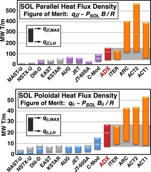
Figure 16. Parallel (top) and poloidal (bottom) SOL heat flux density scale parameters for existing tokamaks compared to ADX, ITER and representative FNSF/FPP/DEMO devices: ARC, ACT1 and ACT2. The top of the vertical bars corresponds to the maximum possible power into the SOL (PSOL,MAX) based on total installed source power, fusion alpha power, and no plasma radiation. Grey bars account for maximum planned upgrades. Upper bars for C-Mod and ADX are for 8 T, 2 MA operation. The bottom of the vertical bars corresponds to setting PSOL equal to the L–H power threshold, PLH, for the device. This is thought to be the lowest allowed value of PSOL consistent with attaining H98 > 1, although as indicated in figure 4, this condition may require unacceptably high levels of core plasma radiation and impurities in fusion reactor plasmas. Thus the bottom of the orange vertical bars indicate the minimum performance parameters that must be demonstrated by advanced divertor solutions before that reactor concept can be considered viable. Experimental tokamaks can test divertor concepts, but only up to their maximum values of PSOL. Thus, in addition to uniquely having reactor-level magnetic field strengths, ADX is uniquely qualified to test divertor solutions at the heat flux densities required to qualify them for FNSF/FPP/DEMO devices (grey shaded region).
Download figure:
Standard image High-resolution imageThe magnitude of the upstream poloidal heat flux density, qθ, can be scaled from another figure-of-merit parameter, PSOLBθ/R. The bottom panel in figure 16 compares PSOLBθ/R among world tokamaks. Again, ADX pushes this quantity far beyond what will be available from current or other planned experiments.
For ITER and devices such as ARC, ACT2 and ACT1, which are representative of FNSF/FPP/DEMO (orange bars in figure 16), it is highly desirable to operate with the lowest possible values of PSOL compatible with obtaining good core plasma confinement. As discussed in section 4.1 (figure 3), data suggest that this lowest value is near the L–H power threshold. Thus the bottom of the orange vertical bars in figure 16 represent the minimum values of PSOLB/R and PSOLBθ/R for which a divertor solution must be found (consistent with good core plasma confinement) before these reactor concepts can be considered viable. Existing experimental tokamaks can test divertor concepts, but only up to the maximum values of PSOL available. Thus, in addition to having the required reactor-level magnetic field strengths, ADX is uniquely able to test divertor solutions at the heat flux densities needed to qualify them for FNSF/FPP/DEMO devices, as indicated by the grey shaded regions in figure 16.
For advanced divertors that attain a fully detached, dissipative plasma condition, PSOLBθ/R is important because it determines the required upstream-to-divertor heat flux footprint expansion factor, i.e., the required spreading of the upstream heat-channel width via radiation and plasma–neutral interactions onto a much larger 'wetted area' in the divertor chamber, as illustrated in the top panel of figure 5. For a maximum surface heat load, qs,max, the expansion factor, S, must be large enough to satisfy the rough inequality, PSOL/(4πRSλq) < qs,max, which accounts for two active divertor chambers. With λq scaling as 1/Bθ, S scales as PSOLBθ/R.
Figure 15 (note 8) shows values of S that are needed to spread the tokamak's total source power uniformly over the surface of two divertor chambers, while keeping the surface heat flux less than qs,max ∼ 5 MW m−2. For ARC, ACT1 and ACT2, expansion factors on the order of ∼1000 are required. These numbers, combined with values of λq ∼ 1 mm from the multi-machine database scaling, determine the minimum size that an advanced divertor chamber must have in a reactor, i.e., the poloidal perimeter of its cross-section must be roughly on the order of 1 m. Thus, the divertor chamber in a reactor will have a cross-sectional size that is actually not much bigger than ADX (figure 13). This fact also tells us that, unlike ADX, advanced divertors in a fusion power plant may not need to occupy a large fraction of the poloidal cross-section of the device. In scaling to a reactor, the cross-section of the core plasma must grow by a factor of ∼5 (ARC) or more (ACT1, ACT2) in linear dimension compared to ADX. But the upstream heat flux width entering into the divertor chamber and the required cross-sectional size of the divertor chamber would remain similar.
For Super-X and X-point target divertors, reactor designs must accommodate the extended major radii of the outer divertor legs. However, if the legs do not extend beyond the outer midplane of the core plasma, the impact on toroidal field magnet design and size is minor [29], particularly in reactor designs that must have the outer toroidal field coil leg extended in major radius to accommodate sector maintenance [80].
Finally, it must be recognized that the physics that underlies the scaling of the heat flux width, λq, is not yet fully understood. The empirical parameterization of upstream λq was obtained for low-recycling divertor regimes in which the 'heat flux footprint' is imprinted on the divertor target and measured by thermography. Further research might find that upstream λq departs from the multi-machine H-mode scaling [14], particularly in dissipative divertor regimes, perhaps exhibiting a positive power law scaling exponent with respect to major radius. This scenario is considered in the last row of data in figure 15 in which λq is taken to scale with major radius. In this case, ADX would access divertor q∥ values that exceed ACT1, ACT2 and all other world tokamaks. In this sense, divertor concepts that prove viable in ADX would be qualified as low-risk options for next-step devices.
7.5. LFS ICRF heating
Through decades of research on the Alcator devices, the MIT PSFC has extensive experience with high power ICRF and LHRF systems—pushing the envelope of high-power antenna technologies and leading the field in the area of RF wave physics [82]. Ion cyclotron range of frequencies (ICRF) hydrogen minority heating of deuterium plasmas has proven particularly effective, coupling up to 6 MW from three antennas on the LFS of Alcator C-Mod (two two-strap and one four-strap) with surface power densities exceeding 10 MW m−2. Most recently, an advanced field-aligned 4-strap antenna [81] has demonstrated remarkable performance compared to conventional antennas: low impurity source rate, excellent load variation tolerance and operation at high neutral pressure. ADX will make use of this breakthrough and employ high power field-aligned antennas on the LFS (figure 17). The vacuum vessel will be specially designed to locate coaxial vacuum feedthroughs at optimal positions with respect to field-aligned antenna elements. RF power systems presently being used for C-Mod would be reused for ADX, upgraded to higher power and modified for higher source frequencies (90–120 MHz) in order to take advantage of the high single-pass absorption of minority hydrogen heating scenarios at toroidal fields in the 6.5 to 8 T range. These systems will deliver ∼8 MW to the plasma, producing power exhaust heat flux densities through the LCFS that are prototypical of a reactor, >1 MW m−2, thus providing the intense auxiliary heating needed to test the advanced divertor concepts on ADX.
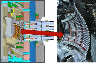
Figure 17. Advanced, field-aligned ICRF antennas developed for the Alcator C-Mod programme (right panel image [81]) will be the primary plasma heating method for ADX, employing hydrogen minority ion cyclotron heating in deuterium plasmas. Three antennas will be deployed on the LFS, delivering 8 MW of absorbed power. Coaxial feeds through the vacuum vessel will be placed at optimal locations with respect to the field-aligned straps.
Download figure:
Standard image High-resolution image7.6. HFS RF systems
In addition to accommodating advanced divertors, the ADX vacuum vessel will be specifically designed to support inside-launch LHCD and ICRF systems. A concept for an embedded RF feed system is shown in figure 18. Waveguide windows and RF feedthroughs are placed inside the toroidal field coils at a small major radius, which has the added benefit of locating cyclotron resonances in the pressurized section of the transmission line, reducing the risk of arcing at high power. These attach to radial feeders that pass between toroidal field coils. It is envisioned that this 'RF plumbing' would be a permanent part of the vacuum vessel infrastructure. LHCD launchers and ICRF antennas would be connected to these feed points and replaced and/or modified as needed via manned access inside the vessel.
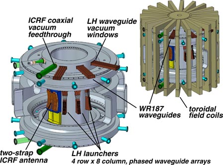
Figure 18. The ADX vacuum vessel will be purpose-built for inside-launch LHCD and ICRF systems. In this concept, ICRF and LHCD vacuum feedthroughs and windows are placed at the top and bottom of the vacuum vessel, with radial RF feeds fitting between toroidal field coils. LHCD will be performed exclusively from the HFS, employing four 4 × 8 phased waveguide arrays (4 MW source power). The vacuum vessel will be designed with sufficient port space to allow all ICRF heating power to be applied via HFS launch as well.
Download figure:
Standard image High-resolution image7.6.1. Inside-launch LHCD
The MIT PSFC presently has 4.6 GHz RF sources with a total power of 4 MW that are used to support the Alcator C-Mod research programme. ADX would utilize these systems for HFS launch LHCD. Figure 19 shows a conceptual design for a launch structure placed below the midplane on the HFS. In this design, the launcher is fed by four WR187 waveguides with each carrying the output from a single klystron. Each waveguide would pass vertically along the inner cylinder of the vacuum vessel and split into four waveguide rows for this conceptual design (similar to the 'LH2' launcher on C-Mod [83]), although space is available to include additional rows. Each vertical waveguide also employs an embedded phase shifter (similar to a bi-junction) to produce the toroidal phasing. Each assembly would form a 4 × 8 phased array, optimized to launch LH waves with n∥ of approximately 1.6, and after waveguide losses, provide 0.5 MW of power to the plasma. A total of four launchers would be employed. The face of the waveguide array would be set slightly behind first-wall protection tiles on the inner wall to prevent damage to the launcher if the LCFS makes contact with the inner wall during startup, rampdown or off-normal events.
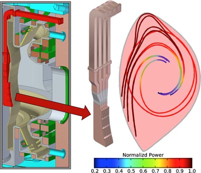
Figure 19. (left) Conceptual design of a HFS LHCD launcher (4 × 8 phased waveguide array) utilizing the vacuum windows and waveguides built into the ADX vacuum vessel. GENRAY/CQL3D modelling for a C-Mod I-mode plasma (right) indicates excellent ray trajectories and good current drive efficiency. The colour scale labelled Normalized Power corresponds to the power in each ray that is damped along that ray path using the quasilinear electron Landau damping from CQL3D normalized to the incident power in the ray.
Download figure:
Standard image High-resolution imageResults from an initial scoping study using the GENRAY/CQL3D ray tracing Fokker–Planck code [84, 85] are shown in figure 19. Target parameters are taken from an Alcator C-Mod I-mode plasma: 5.6 T, 1.0 MA, central density of 1.8 × 10²⁰ m−3 and central temperature of 5.5 keV. Waves are launched with a unidirectional spectrum at n∥ = 1.6. As anticipated, favourable trajectories with excellent radial penetration are obtained when launched from the HFS below the midplane of the device, producing a broad non-inductive current profile. The poloidal 'steering' technique shown in figure 19 takes advantage of the combined effects of toroidicity and poloidal magnetic field that characterize off midplane launch and that result in a steady increase of parallel wavenumber as the ray propagates to the plasma core. Furthermore, HFS launch takes advantage of the low PMI and good RF coupling properties of the local SOL, as discussed in section 5.2.
The predicted wave propagation in figure 19 is qualitatively different from what was observed in the poloidal 'steering' study of the LFS launcher on Alcator C-Mod, where the launcher poloidal angle was optimized to achieve high single-pass absorption. In order to illustrate the difference, figure 20 shows a comparison of the LH wave propagation characteristics and absorption profiles for the HFS launcher and a LFS launcher with launched n∥ = 1.6 and 2.5, respectively. The LFS launcher is located at the same height as the launcher in [59]. The radial power deposition profile (and also the driven current density profile—not shown) for HFS launch is distributed through the core region from 0.2 ⩽ r/a ⩽ 0.65 with a peak at r/a ≈ 0.3. In contrast, the LFS case has a power deposition profile with a narrow peak at r/a ≈ 0.6; only small levels of LH power make it into the core region. The ability to couple faster phase velocity waves (i.e. lower n∥) from the HFS makes it possible to drive current farther into the hot plasma core where high current drive efficiency is possible
 .
.

Figure 20. Comparison of LH wave propagation and absorption in ADX (B0 = 5.6 T, Ip = 1.0 MA, ne(0) = 1.8 × 10²⁰ m−3, Te (0) = 5.5 keV) for HFS and LFS launch at n∥ = 1.6 and 2.5, respectively. Shown is the LHRF power deposition (W cm−3) versus r/a with an inset of the poloidal projection of the ray trajectories.
Download figure:
Standard image High-resolution imageThe density range over which lower hybrid waves are accessible to ADX plasmas is illustrated in figure 21, comparing HFS and LFS launch cases. High magnetic field strength combined with HFS launch provides excellent LHCD access in ADX. For on-axis magnetic fields greater than 6.5 T, lower hybrid waves launched with n∥ = 1.6 from the HFS would have access to plasma densities at r/a ∼ 0.75 approaching or exceeding ne ∼ 2 × 10²⁰ m−3—a factor of ∼3 increase in plasma density compared to LFS launch.

Figure 21. Comparison of LH wave accessibility in ADX for HFS and LFS launch. With on-axis toroidal fields of 6.5 T, HFS lower hybrid waves at n∥ = 1.6 access r/a = 0.75 with local densities approaching ne ∼ 2 × 10²⁰ m−3, a factor of 3 higher density than for LFS LH waves.
Download figure:
Standard image High-resolution image7.6.2. Inside-launch ICRF:potential elimination of boronization
It is anticipated that the primary plasma heating systems on ADX will be field-aligned ICRF antennas located on the LFS (section 7.5). This robust, proven technology can deliver the power needed for ADX's advanced divertor mission. However, as indicated in section 5.2, there are many compelling reasons to implement HFS launch for all RF systems. In addition to the beneficial RF physics, this configuration would essentially eliminate all impurity sources on the LFS that would otherwise be in close proximity to the plasma (launchers, protection limiters), potentially yielding an order of magnitude reduction in core plasma impurity level for sputtered and non-recycling impurities (see figure 9). Indeed, experiments with boronization on Alcator C-Mod found that the most important surfaces to boronize are the ones located on the LFS [5]. Thus, implementing HFS launch for all RF systems would go a long way towards eliminating the need to apply low-Z coatings for impurity control—a technique that does not scale well to a reactor. For this reason, the ADX vacuum vessel will be designed to accommodate HFS ICRF antennas (figure 18) with the intention of migrating all ICRF power to that location. In principle, four two-strap antenna systems (8 MW delivered) can be implemented on the inside wall, while still accommodating room for four LHCD launchers.
Figure 22 shows a conceptual design for a two-strap, HFS ICRF antenna option in ADX. Each strap would be centre-grounded and fed symmetrically by RF striplines that pass vertically along the inner wall to coaxial vacuum feedthroughs. The antenna straps and Faraday cage could also be tilted off vertical (∼6°) to align these components approximately with the local pitch of magnetic field lines—a field-aligned antenna for the HFS, although this is not depicted in the design drawing in figure 22.
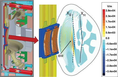
Figure 22. Conceptual design for a two-strap ICRF antenna on the HFS of ADX. Coaxial RF vacuum feedthroughs connect to vertical striplines that feed a symmetric, centre-grounded antenna mounted on the inner wall (left). TORIC modelling using a C-Mod plasma reveals excellent single-pass absorption and direct electron heating, facilitated by efficient mode conversion to IBW. Contours of the left circularly polarized component of the ICRF electric field in (V m−1) for 1 MW of absorbed power are shown on the right. Locations of the ion–ion hybrid layer (Xii) and hydrogen cyclotron layer (XH) are shown.
Download figure:
Standard image High-resolution imageTORIC simulations have been used to explore HFS ICRF wave propagation physics in ADX, using representative C-Mod plasmas. As anticipated, incident fast waves mode convert directly to IBW and ICW [86]. This is because the fast-wave branch connects directly to IBW/ICW branches at the ion–ion hybrid layer. In contrast, fast waves launched from the LFS must tunnel past the hydrogen cyclotron resonance layer to get there. The mode converted waves damp directly on electrons via linear electron Landau damping and the relative balance between ion/electron absorption may be controlled via the hydrogen minority fraction, nH/ne. For nH/ne ∼ 0.15 (case shown in right panel of figure 22) the incident fast-wave power is absorbed nearly 100% via mode conversion. This is a very important result—complete absorption of the incoming fast wave is obtained without formation of energetic ion tails. This means that issues associated with fast ion loss or destabilization of energetic particle populations (including fusion alphas in a reactor) are eliminated and resultant fast-ion induced sputtering of first-wall components is suppressed. High single-pass absorption for the fast wave is also very important for suppressing RF-enhanced sputtering associated with fast waves impinging on first-wall surfaces, converting to slow waves and causing large sheath potentials due to sheath rectification effects. This mechanism was shown to be very important in C-Mod [87] and would be virtually eliminated in ADX with HFS launch. The fast-wave to IBW mode conversion scenario is also attractive as a physics tool because it has been found to produce poloidal flow drive in Alcator C-Mod [88] and TFTR [89]. With 100% of the fast-wave power undergoing mode conversion, HFS ICRF launch may provide an essential tool—perhaps the only tool available—to produce and control flow shear in the core of a reactor at the levels needed to suppress plasma turbulence. Experiments in C-Mod (with LFS launch) have already demonstrated toroidal velocity drive of up to ∼30 km s−1 MW−1, which is comparable to neutral beam injection in JT60-U and JET [90].
7.6.3. Current profile control in ADX
ADX has all the critical elements needed for successful current profile control, namely, high LHCD efficiency with broad off-axis LH current density profiles in discharges with high bootstrap current fraction. The high available ICRF heating power (∼8 MW) and strong ICRF absorption scheme (hydrogen minority in deuterium) is expected to provide high enough electron temperature target plasmas (Te(0) > 5−6 keV) for near 100% single-pass absorption of the LHCD power at line average densities of ∼1.4 × 10²⁰ m−3, thus avoiding parasitic absorption mechanisms associated with weak single-pass damping in present-day experiments [54, 59, 91]. Furthermore, with direct electron heating from HFS ICRF, it will be possible to achieve hotter electron temperatures in high βp discharges. Increasing βp facilitates access to advanced tokamak regimes with high bootstrap current. The degree to which the remaining current can be replaced by bootstrap current will then depend on the radial extent of the transport barrier that can be triggered with off-axis LHCD as well as the confinement properties of the reversed-shear plasma (see for example [6, 7]).
8. Critical need: core and pedestal physics research at reactor-relevant conditions
Not only will ADX be an essential facility to develop divertor and RF sustainment solutions, it will also be an essential platform for core and pedestal physics research at highly reactor-relevant parameters. By using exclusively RF actuators, the device will have no core fuelling or external torque. Core parameters are expected to push well beyond those on C-Mod, which has achieved central electron temperatures exceeding 8 keV and currently holds the record for average plasma pressures (1.8 atm). Presently, the pressure on C-Mod is limited by available heating power and the lack of high-power divertor solutions that avoid high levels of impurity radiation, e.g. the tradeoff between divertor survival and core plasma performance described above in section 4.1. High-Z impurity influx at high powers also is a limitation, particularly at lower plasma densities. With heating source power increased from 8 MW (C-Mod) to 14 MW (ADX), the success of advanced divertors, optimized RF launchers and techniques to dramatically reduce plasma–wall interactions (HFS launch, elimination of LFS PMI) will combine to break through these barriers. Thus ADX will, for the first time, provide access to reactor-relevant values of both absolute and normalized pressures, and study crucial core and pedestal physics issues needed for a reactor, which must operate at similarly high—or higher—magnetic field.
A particularly valuable research tool in ADX is the ability to perform high-field launch LHCD for current profile control. Efficient wave coupling and enhanced current drive efficiencies would enable the exploration of non-inductive scenarios at higher plasma densities while at the same time modifying the current profile to improve core plasma confinement. An important research topic will be exploring the level of H98 that can be routinely attained in ADX and projecting those results to reactor scenarios. ICRF mode conversion flow drive, which is expected to be enhanced significantly by HFS launch, is another unique tool that ADX can apply in this area. Another critical research topic for ADX is seeking out and exploring physics of high-performance ELM-suppressed pedestals, their operational space, compatibility with advanced divertor solutions and applicability to a reactor. ELMs are not allowed in a reactor—therefore an assessment of the ability to operate in naturally ELM-suppressed regimes is critically important. However, as a backup plan, one may also consider implementing active ELM control via resonant magnetic perturbations and/or pellet pacing.
Outlined below are focused areas of research that would directly target ADX's milestone #3, restated as: Achieve [divertor power handling and erosion control] while demonstrating a level of core and pedestal plasma performance that projects favourably to a fusion power plant and in physics regimes that are prototypical.
8.1. Core confinement physics
It is well recognized that core plasma energy confinement, as commonly characterized by H98, is a critical parameter that determines the viability of next-step devices. Uncertainty in the H factor at the 10% level can make the difference between success and failure for a burning plasma experiment or a fusion power plant [92]. Moreover, enhanced levels of H98 are often assumed in reactor designs. Although much progress has been made in core transport modelling, first-principles quantitative prediction is well beyond our current capabilities. Prediction of pedestal performance in ELM-suppressed and ELM-less regimes is even more daunting. We have no physics-based models that can make quantitative predictions for such discharges. To minimize the degree of extrapolation for future devices, experiments in the right regime (magnetic field, plasma density, with electron heating and equilibrated electrons and ions, and ELM-suppressed) and with the right heating and current drivers (i.e. with no particle or momentum source) and with the right divertor geometry and materials are crucial.
While general studies of transport continue to be important, research on ADX would focus on the ability to robustly and reliably attain H98 above 1 using only the class of tools and wall materials that would be available in a reactor. The high-field launch LHCD system should allow attainment of low-shear and reversed-shear equilibria [6] that have been shown to lead to improved energy confinement [93]. At the same time, physics-based models would be tested and calibrated to allow application in reactor regimes with minimal extrapolation and high confidence. To properly characterize transport models, comparisons of experimental fluxes, profiles and fluctuations with those derived from simulations must be analysed with modern statistical tools [94].
Without a means to apply significant external torque—which is the case for ADX and the expectation for a fusion reactor—a main control knob for core transport is the current profile. This is predicted from linear gyrokinetic theory as well as nonlinear simulations that show a strong dependence of critical gradients on magnetic shear [93]. ADX would provide an ideal platform on which to study the effects of magnetic shear on the achieved gradients and overall confinement. A key goal would be the development of scenarios that feature enhanced core confinement in non-inductive operation, made possible with the proposed current drive tools.
The origins of intrinsic rotation and its role in setting the transport levels would also be a point of focus. Significant levels of flow and flow shear are commonly present in plasmas without external torques [95] and C-Mod has already operated in regimes where the flow shear from intrinsic rotation enables creation of ITBs [96]. Even with lower levels of rotation, the shear could have a quantitative effect that must be characterized and understood. ICRF mode conversion flow drive, enhanced by HFS launch, is expected to produce significant flow shear in the core plasma of ADX. This can be used for physics studies and for the enhancement of core plasma performance [88]. Most importantly, ICRF mode conversion flow drive may be a means to affect flow profiles in the core of a reactor. Its physics and the prospect for its application to reactor-scale devices is therefore an important area of study in ADX.
With 10 MW of auxiliary power delivered to the plasma, ADX is expected to attain values of βN(= 〈β〉aBT/Ip) in the range of ∼1.5%. This is well below the threshold for external kink modes but may be sufficient to trigger neoclassical tearing modes and, without mitigation, could lead to confinement degradation. Although such modes would not impact ADX's divertor mission, their presence would provide an opportunity to demonstrate techniques for control and suppression. ADX has a number of RF actuators for this task: elevate qmin and tailor current profile with application of LHCD, reduce/eliminate sawtooth triggers by application of ICRF mode conversion electron heating and current drive (as demonstrated in C-Mod [97]) and affect flow shear via application of ICRF mode conversion flow drive.
ADX would address the issue of electron–ion coupling and the effect that has on gradients relative to the marginal stability point for each species. Strong electron–ion equilibration can have deeper effects than simply Ti ∼ Te (though this is an important consequence for micro-stability). For strongly equilibrated plasmas (as reactor-grade plasmas must be) both ion and electron temperatures will be close to marginal stability for the species with the lower critical gradient length. If the critical gradient length profiles for the two species are not identical—and in general they will not be—then the turbulence may be heavily influenced by the species providing the marginal stability. This is unlike the case of heating each species to approximately the same temperature in an uncoupled plasma, where each is independently driven to marginality. Thus the turbulence dynamics may be quite different for the two cases. This may be particularly important for 'other' transport channels—that is, it may be critical for predicting density and rotation profiles which are expected to respond quite differently in plasmas dominated by electron versus ion turbulent transport.
8.2. Pedestal physics—ELM-suppressed regimes
Enhanced core performance in present-day and future devices depends on the attainment of edge transport barriers; these are the 'pedestals' on which core profiles build. However current understanding of pedestal physics—the conditions for barrier formation, the transport and stability physics that regulate them—is far from complete, particularly in regimes relevant for reactors: good core confinement, ELM suppression, acceptable levels of divertor heat load and target erosion, and at the same time, dealing with reactor-level power exhaust densities. In this regard, ADX is an essential pedestal physics research tool for the world research programme. With the implementation of an advanced divertor that can successfully handle plasma exhaust surface power densities well above 1 MW m−2 with minimal negative impact on the confined plasma, ADX would achieve unprecedented pedestal parameters. Based on extrapolation from C-Mod results [98], and using the EPED-like scaling pped ∼ BTBPOL [39], the ultimate pressure pedestal achievable on ADX could push well past that of any existing machine, even topping expected values for ITER (∼0.1 MPa). H-mode pedestals with normalized power PSOL/PLH in the range of 2–3 would be attained, promoting access to enhanced H98 (see figure 3) and low pedestal collisionality (ν* < 1). Access to these unique conditions will test existing pedestal models (e.g. EPED [39]) and new first-principles models as they emerge. A particular focus will be on the critical task of assembling the database required to project pedestal conditions in ELM-suppressed regimes.
At high plasma densities, ADX should trivially access enhanced D-alpha (EDA) H-mode, one of the most well understood variety of stationary ELM-suppressed high-confinement regimes [99]. EDA H-mode would be a good initial platform for developing advanced divertor solutions that can fully mitigate heat fluxes, suppress divertor target erosion, while maintaining a hot pedestal—extending beyond the dissipative divertor studies with ITER-like target geometries pioneered in Alcator C-Mod [18]. Ultimately, operation in stationary low-collisionality regimes must be demonstrated and found compatible with an advanced divertor concept.
A promising ELM-suppressed, high energy confinement regime is the I-mode [8]. I-modes have temperature pedestals without density pedestals, L-mode impurity confinement and energy confinement that exhibits relatively weak degradation with heating power,
 , which scales very favourably for reactor operation. Recent work on C-Mod and other tokamaks shows that the window for I-mode opens up substantially at high magnetic field [100]. Data from C-Mod (figure 23) delineate the I-mode window in terms of toroidal magnetic field and input power (Ploss), normalized by density and plasma surface area, Ploss/neS. These data are for single-null operation with unfavourable grad-B drift direction. The L- to I-mode power threshold (L–I) is independent of magnetic field while the I- to H-mode threshold (I–H) increases strongly with field, ∼B0.78. The access region for I-mode forms a triangle in this parameter space. These data imply that I-mode could be readily accessed on ADX with only 1.6 MW at line average densities of 1020 m−3, while by increasing the density to 2.5 × 10²⁰ m−3, it should be maintained up to 12 MW of power. I-mode has been shown experimentally to be compatible with near-DN configurations, although more studies are needed to examine the heat flux sharing in this configuration. ADX will have the flexibility in input power and magnetic topology to explore I-mode in a comprehensive way, examining synergies with advanced divertors and developing physics-based understandings of pedestal transport and stability to guide its development as a reactor regime.
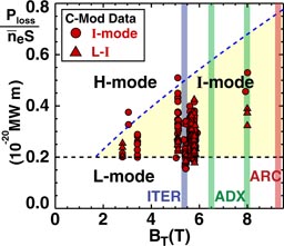
Figure 23. Normalized input power, Ploss/neS, versus toroidal field for discharges that attained I-mode in Alcator C-Mod. L–I transitions show little field dependence, while the upper range of powers, typically set by I–H transitions or at high field the available power, increases strongly with B. Note that the few 8 T cases used a weak ICRF absorption scheme, hence powers may be overestimated. I-mode is an attractive regime for ITER and ARC, and would be explored fully in ADX. Experimental conditions are described in [100].
Download figure:
Standard image High-resolution image
The attainment of low collisionality pedestals at high pressure and high power (made possible with advanced divertors) combined with the ability to modify edge current profiles (inside-launch LHCD) would allow ADX to explore regions in pedestal MHD stability space that would otherwise be inaccessible—shifting the balance between pressure-driven versus current-driven instabilities in determining the limits on the pressure pedestal. ADX will use these tools to seek out and evaluate additional regimes with continuous edge relaxation mechanisms, like QH-mode [101], or the recently predicted super-H-mode [102].
8.3. Active pedestal control options
Naturally occurring ELM-suppressed regimes are the first choice for reactor operation and they would be most vigorously pursued in ADX. However, one can consider systems for active control of the pedestal in ADX (e.g., ELM suppression, enhanced impurity transport), such as via the application of resonant and non-resonant magnetic perturbations [103] or specially designed antennas to excite edge modes [104, 105]. Although not yet included in the conceptual design outlined above, ADX could readily accommodate such systems. With all RF systems moved to the HFS, there would be ample room for a set of low n/m in-vacuum coils or antenna structures to be placed on the LFS. However, the benefits of these systems, beyond being interesting physics tools, must be weighed against their complexity, risk and scalability to reactors.
9. Summary
The tokamak is the most advanced magnetic plasma confinement device ever devised; it has the potential to produce abundant energy from plasma fusion. Based on the confidence gained from decades of core confinement physics research, ITER in its D–T phase is projected to produce 10 times more power out than in. Moreover, recent developments in high-temperature, high-field superconducting magnetics hold promise that this same core physics may lead to a compact electricity-producing pilot plant, as envisioned in the 'affordable, robust, compact' (ARC) concept [11]—a facility no bigger than devices operating today but producing hundreds of megawatts of net electricity. This approach is particularly exciting because it does not push core performance beyond what has already been attained. However, order-of-magnitude improvements of the support systems are still required for any tokamak that aspires to produce net electricity—robust systems for power/particle handling, erosion control, and steady-state RF current drive—and these systems must utilize techniques that are compatible with attaining a burning plasma core. Nevertheless, with the possibility of constructing high-field, compact, superconducting tokamaks, magnetic fusion has entered a new era: core plasma confinement appears good enough. The viability of the tokamak as a fusion device now depends on demonstrating solutions for the supporting technologies.
Fortunately, decades of research have also revealed detailed information about the physics of boundary plasma, divertors, RF wave propagation and RF actuators. As outlined in sections 4 and 5 of this paper, exciting new ideas exist for order-of-magnitude improvements in power exhaust/erosion handling (e.g., Super-X divertor, X-point target divertor, liquid metal targets) and techniques for efficient, low plasma-material interaction RF actuators for heating and current drive (e.g., high-field side launch LHCD and ICRF, double-null plasmas). These are the kinds of approaches needed to make fusion energy a reality. Unfortunately, no facility presently exists in the world (nor is any being built) that is able to test these ideas at the plasma conditions required to qualify them for a reactor or that has the flexibility to fully implement these approaches. For example, in order to obtain the appropriate divertor physics/PMI regime in terms of dimensionless parameters, the absolute magnitudes of magnetic field and parallel heat flux density must be the same as in a reactor (section 4.4). In order to implement inside-launch RF systems, a tokamak must be designed from the outset with the infrastructure for this purpose.
Recognizing this critical gap in the world fusion research programme, the MIT Plasma Science and Fusion Center and collaborators are proposing a high-performance, high-field Advanced Divertor and RF tokamak eXperiment, ADX—a tokamak with the ability to develop and test innovative power/PMI handling and RF current drive/heating ideas at the performance parameters (power/particle flux densities) and plasma physics parameters (plasma density, magnetic fields, current relaxation time relative to pulse length) required to qualify them for next-step devices. The mission for ADX can be stated simply: identify, develop and demonstrate plasma exhaust, plasma-material interaction and RF current drive/heating solutions at reactor parameters that are compatible with obtaining high confinement core plasmas, and that scale to long pulse plasma operation. Progress on this mission can be measured against the attainment of five key milestones, as outlined in section 3.
An initial design concept for ADX is presented. It uses the proven magnet technology developed for the Alcator programme: demountable LN2-cooled copper toroidal field magnetics (6.5 T nominal, 8 T possible), rigid vacuum vessel supporting internal poloidal field coils configured for advanced divertor geometries and incorporating inside-launch LHCD and ICRF systems. It makes use of the extensive infrastructure and expertise at MIT that presently supports the C-Mod facility (experimental cell, power systems, control systems, RF systems, diagnostics, etc). As a starting point, the 'footprint' of ADX is kept the same as Alcator C-Mod, allowing major structural components to be reused. The vacuum vessel and overall height is extended by 0.5 m. This provides sufficient room for an arrangement of poloidal field coils that can produce a variety of advanced high-performance magnetic divertor configurations. A modular vacuum vessel design can accommodate the coil set. In addition, it allows subsections of the vessel to be customized and tested off-line to prepare for different divertor coil arrangements, the use of liquid metal targets and/or heated target assemblies. The vacuum vessel also has sufficient room for embedded waveguides and RF feeds to power LHCD launchers and ICRF antenna structures located on the inside wall. Conceptual designs are presented for an inside-launch 4 × 8 LHCD phased array and a two-strap ICRF antenna. Initial assessments of plasma wave physics from both systems are very favourable—good LH current drive and excellent ICRF absorption. The ICRF scenario makes use of an efficient fast wave to ion Bernstein wave mode conversion scheme, which produces direct electron heating, avoids the formation of high energy ion tails and suppresses the level of unabsorbed fast-wave power incident on first-wall surfaces, which has been linked to RF-enhanced energetic ion sputtering via sheath rectification.
While the vacuum vessel is designed to accommodate high-field side launch of all RF power, it is envisioned that ADX will start its mission with low-field side ICRF systems, making use of a high-performance field-aligned antenna design, which has demonstrated excellent performance in Alcator C-Mod. This low-risk technology (8 MW coupled to plasma) will insure a fast-start for the divertor physics mission and allow a parallel exploration of inside-launch ICRF options. Inside-launch LHCD would be implemented from the beginning, employing up to four launchers (2 MW coupled to plasma). Additional launchers and LHCD power could also be added in later upgrades.
Based on extensive operational experience from Alcator C-Mod, including boronization of its high-Z wall at different major radii [5], we believe that the ultimate solution for attaining high plasma performance in reactor is to implement high-field launch for all RF systems. The ADX research programme would target this goal. In addition to taking advantage of highly beneficial RF physics, this configuration would essentially eliminate all impurity sources on the low-field side that would otherwise be in close proximity to the plasma (launchers, protection limiters). Instead, such impurity sources, if they still occur, would come from the high-field side. This would exploit the excellent impurity screening behaviour of the scrape-off layer at this location, which could produce an order of magnitude reduction in core plasma impurity level (figure 9). This is another potential game-changing approach for magnetic fusion—eliminate the need to apply low-Z coatings for impurity control (e.g., boronization), a technique that does not scale well to a reactor.
The combination of increased heating power, advanced divertor solutions, optimized RF launchers and reduced impurity levels has the potential to push core and pedestal plasma parameters well beyond that of Alcator C-Mod, which has already achieved central electron temperatures exceeding 8 keV and holds the record for average plasma pressures (1.8 atm). Thus ADX will, for the first time, access reactor-relevant values of both absolute and normalized pressures, and push pedestal parameters into reactor regimes. This will allow exploration and optimization of favourable ELM-suppressed pedestal regimes such as the I-mode, which has a large operating window at high magnetic fields. ELMs cannot be tolerated in a reactor. The importance of having a research platform to perform this research cannot be overstated.
ADX is prototypical in many ways for an ARC-like reactor concept: exclusive use of RF systems for heat and current drive, including inside-launch LHCD; operation at high absolute plasma pressure but moderate plasma beta; equilibrated electrons and ions; operation in regimes with low or no torque, and no fuelling from external heating and current drive actuators. This gives ADX the unique opportunity to explore enhanced core confinement physics, such as made possible by reversed central shear, using only the types of external actuators that are considered viable for a fusion power plant. Such an integrated demonstration of high-performance core-divertor operation with steady-state sustainment is precisely what is needed to inform the development pathway towards an ARC-like reactor concept.
ADX is conceived as a national facility. It is envisioned as an experimental platform to engage experts, both nationally and internationally, from a broad range of expertise: advanced divertors, advanced RF systems, core plasma, pedestal, boundary layer and plasma–wall interaction physics—to attack the next level of challenges on the road to fusion energy. The conceptual design outlined here is just a sketch of what could be done with a 6.5 to 8 T tokamak, using existing technology and existing infrastructure at MIT. ADX will undoubtedly evolve, and we hope that it does, guided by input from all those who wish to participate.
Acknowledgments
The ADX concept is being refined with support from many colleagues. We especially acknowledge: N. Asakura, D. Brower, L. Delgado-Aparicio, R. Goldston, S. Krasheninnikov, D. Ryutov, S. Scott, P.C. Stangeby, G. Tynan and F. Waelbroeck. This work is supported by US DoE agreement DE-FC02-99ER54512.
Footnotes
- 7
Heat flowing poloidally at the outer midplane (qθ) passes through an area 2πλqR, which sets its magnitude as qθ ∼ Psol/2πλqR. Parallel heat transport is the dominant contribution to the poloidal heat flux, q∥ ∼ qθB/Bθ. The scaling λq ∼ 1/Bθ implies that q∥ scales as ∼PsolB/R.