
Abstract
Use of 2G HTS coated conductors in several power applications has become popular in recent years. Their large current density under high magnetic fields makes them suitable candidates for high power capacity applications such as stacks of tapes, coils, magnets, cables and current leads. For this reason, modeling and simulation of their electromagnetic properties is very desirable in the design and optimization processes. For many applications, when symmetries allow it, simple models consisting of 1D or 2D representations are well suited for providing a satisfying description of the problem at hand. However, certain designs such as racetrack coils and finite-length or non-straight stacks, do pose a 3D problem that cannot be easily reduced to a 2D configuration. Full 3D models have been developed, but their use for simulating superconducting devices is a very challenging task involving a large-scale computational problem. In this work, we present a new method to simulate the electromagnetic transient behavior of 2G HTS stacks and coils. The method, originally used to model stacks of straight superconducting tapes or circular coils in 2D, is now extended to 3D. The main idea is to construct an anisotropic bulk-like equivalent for the stack or coil, such that the geometrical layout of the internal alternating structures of insulating, metallic, superconducting and substrate layers is reduced while keeping the overall electromagnetic behavior of the original device. Besides the aforementioned interest in modeling and simulating 2G HTS coated conductors, this work provides a further step towards efficient 3D modeling and simulation of superconducting devices for large-scale applications.
Export citation and abstract BibTeX RIS
1. Introduction
The high current carrying capacity at high temperatures, decreasing price ($ kA−1 m−1) and availability in long lengths of second generation (2G) HTS tapes has made them excellent candidates for several power applications. Use of 2G HTS tapes allows compact designs for cables such as Roebel [1] or twisted stacked-tape cable conductors [2], magnetized stacks [3] and large magnet coils [4–6] among others. All these designs share one common structural feature: a cross-sectional plane shows a stack-like structure. For instance, besides the case of magnetized stacks, uniformly packed coils can be seen as a stack-like conductor making a closed loop and Roebel cables can be modeled as a pair of stacks of tapes.
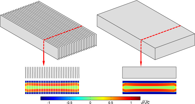
Figure 1. Comparison of a complete model considering the actual layout of a stack of superconducting tapes (left) and its corresponding homogenized model (right). The corresponding normalized current density distributions are shown at the bottom. For visualization purposes, in the model corresponding to the actual geometrical layout, the superconducting layers' actual thickness is artificially expanded during post-processing.
Download figure:
Standard image High-resolution imageUnderstanding and being able to predict the behavior of such devices is of large importance for design and optimization purposes. Hence, tools for modeling and simulating their electromagnetic properties are necessary in this process. To this day, several models capable of simulating infinitely long stacks composed of many 2G HTS tapes are already available [7–10]. These models provide a very valuable tool for analyzing long straight stacks and large circular coils. However, for most of the aforementioned power applications, 3D models are needed to take into account several factors such as the end effects in magnetized stacks or current leads, the structure of racetrack or saddle coils or even the interaction of long cables used in windings. Nevertheless, developments in 3D models for these 2G HTS tapes stack-like devices are scarce and limited to particular cases such as modeling of Roebel cables [11, 12]. In this work, we present a homogenization tool for modeling and simulating these stack-like devices in 3D.

Figure 2. Domains used for imposing the integral constraints in a stack of tapes. Actual stack layout in which all the tapes are considered (a), one integral constraint per conductor is needed. Homogenized domain (b), only one integral constrain is needed. Discretized homogeneous domain (c), one integral constraint per subdomain is needed.
Download figure:
Standard image High-resolution imageLarge circular coils and stacks made of 2G HTS tapes have already been modeled taking into account the actual layout of the materials in the composing tapes up to the μm scale. Examples of such 2D simulations are found in [7] and [13] among others. However, computation of large-scale stack-like devices is a time demanding task. Several 2D approaches using homogenization techniques have been proposed as a way to reduce the computing time needed to estimate AC losses in superconducting stacks of finite height [9, 10, 14, 15]. In particular, for large stacks modeled in 2D, use of an anisotropic homogenous-medium approximation has provided a speedup of two orders of magnitude in the computational time without undermining accuracy when compared to calculations made using models describing the internal geometrical layout [10]. The main goal of this work is to present the extension of the 2D homogenization technique introduced in [10] to 3D, so that more complex stack-like structures can be modeled and simulated with ease and within a reasonable computing time.
2. Methodology
Following the 2D method presented in [10], in this work we extend that approach to the 3D case. All calculations presented here are carried out using the H-formulation of Maxwell's equations as described in [10, 16]. The main idea is to find a homogeneous anisotropic bulk-like material that retains the overall electromagnetic properties of a stack of tapes carrying the same current each but with a much simpler geometrical layout that does not include the individual tapes of the stack. The general concept is presented in figure 1 by considering an infinite stack of tapes for the sake of simplicity. Since the problem is essentially a 2D problem, the comparison is made using the material properties and the method as described in [10]. Here, the features on the left correspond to the actual stack where the geometrical layout of the individual tapes is considered. The right side of the figure presents the homogeneous bulk model. The lower part of figure 1 shows a cross-sectional view of the current distributions obtained for both the model depicting the actual geometrical layout of the stack and its corresponding homogeneous bulk model. As already pointed out in [10], one can note that good agreement between both current profiles is obtained. To guarantee that the current distribution in the homogenized stack corresponds to an equal current share in each conductor, integral constrains are used. The following section describes their main features and techniques regarding their implementation.
2.1. Integral constraints
When considering a stack of tapes carrying the same current, as it is the case for the cross section of a coil, integral constraints can be used. In that way, the net current within each conductor is set to a given value. Considering the stack of nc tapes presented in figure 2(a), a set of integral constraints of the form

guarantees the requested current share. Here J is the current density,  is the current imposed to each tape and
  is a unitary vector defined locally as being tangential to the tapes in the stack, pointing in the intended direction of the current flow. One can note here that the position
  where the constraint is placed is arbitrary, as the high resistivity of the air or insulation domain will prevent the current from flowing outside the superconducting domains. This makes fk uniform and equation (1) can be rewritten as:

Use of (1) for the anisotropic homogenous-medium approximation (see figure 2(b)) is not possible as there are no longer any separated conductors that could be individually considered. Therefore, a different approach should be used to ensure the desired current distribution. For this purpose, one can consider the homogenized stack as being composed of infinitely thin tapes. Then, the following condition:

can be used to impose a current  to every one of these thin tapes. One must note again that in the case of stacks and coils where individual tapes share the same current, g becomes uniform. Therefore, the aforementioned constraint becomes:

In the following subsections three different ways to impose this condition are presented.
2.1.1. 2D integral constraint
A first approach is the direct enforcement of (4). Numerically, this requires defining an integral constraint in 2D. In this way, the constraint should specify the total current flowing tangentially to the tapes in the stack or winding in the intended direction of the current flow. For an infinite stack as in the one presented in figure 2, this tangential direction is parallel to the  vector, so
  . In the case of a racetrack coil whose straight section of length 2 y0 is aligned with the direction as the one in figure 3, is given by the following expression:
One can note that circular planar coils can also make use of (5) by setting y0 = 0. In general, expressions for other, more complicated, windings or stack-like structures can easily be found provided that the packing of the tapes is uniform. Constraint (4) can then be imposed by means of Lagrange multipliers.
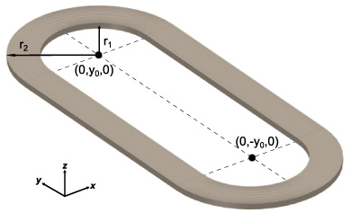
Figure 3. Geometrical layout of a racetrack coil.
Download figure:
Standard image High-resolution image2.1.2. Use of anisotropic resistivity
One alternative procedure is to use an anisotropic resistivity tensor that provides a very high resistivity in the direction normal to the tapes' surface. Therefore, the E–J relationship can be expressed as:

Here, ρ∥ corresponds to the homogenized resistivity of the superconducting stack and ρ⊥ is an artificially imposed high resistivity used to prevent current flow in the direction normal to the tapes' surface.
2.1.3. Manual discretization of the homogenized bulk
Alternatively, and following a similar approach as the one presented in [10], a manual discretization approach is considered. This implies partitioning the homogenized bulk in smaller domains following the direction tangential to the tapes windings as shown in figure 2(c). The rationale behind this simplification is that in large coils or stacks, neighboring tapes experience similar electromagnetic conditions and hence behave in a comparable manner. To prevent current sharing among the subdomains, highly resistive layers are placed between them. Then the subdomains Ω1, Ω2, ..., Ωns, of the homogeneous bulk correspond to a bundle of neighboring tapes. Hence, by using only one element to discretize the thickness of the subdomain, a similar behavior for each tape in the bundle is ensured. Computationally this has a similar effect to the strategies discussed in the previous sections, but allows for a finer control upon the mesh density, the number of degrees of freedom and ultimately the computational time required for simulations.
2.2. Jc(B) dependence and E−J relationship
As mentioned before, in this work, all calculations are made using the H-formulation of Maxwell's equations [16]. To account for the magnetic flux density dependence of the critical current density Jc, the following expression is used:
here B∥ and B⊥ are respectively the parallel and perpendicular components of the magnetic flux density. The parameters Jc0, k, Bc and b have the respective values of 49 GAm−2, 0.275, 32.5 mT and 0.6. These parameters correspond to a characterization (not reported here) for the Jc(B∥, B⊥) for the HTS tape used in [17] using an elliptic fit. This corresponds to a self-field critical current Ic of 160 A at 77 K. The remaining parameter, fHTS, is the volume fraction of the superconducting material in the homogenized bulk[10]. In what follows, we will refer to Jc(B∥, B⊥) simply as Jc(B). To describe the E–J relationship, a power law is used:
here, the critical electrical field E0 at which J = Jc(B∥, B⊥) is set equal to 1 μV cm−1. The exponent n = 21 in the power law is used to describe how abrupt the transition from the superconducting to the normal state is.
3. Results
In this section first we present a validation test case for the proposed homogenization method, then we apply it to simulate a typical 3D case: racetrack coils.
3.1. Test case for validation
To validate the proposed strategy, the case of a stack consisting of 50 4 mm-wide tapes having a total height of 2 cm was considered. Assuming a thickness for the superconducting layer of each tape of 1 μm, this corresponds to a volume fraction, fHTS of 2.5 × 10⁻³. AC currents at 50 Hz were imposed in each of the tapes in the stack. The straight stack was modeled following two different approaches: a 2D model for large stacks as described in [7] which takes into account the 50 different conductors in the original layout of the stack, and the 3D homogenized model as described in the previous section. Since the conductivity of the superconducting layers is much higher than that of the other materials involved, and no magnetic substrate is used, only the superconducting layers were simulated. As a mean to compare both models, AC losses were computed for different current amplitudes. The results are shown in figure 4. It is important to note the good agreement over the large range of applied currents and over more than two orders of magnitude for the calculated AC losses.
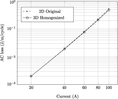
Figure 4. Comparison of the AC loss in a stack by modeling the original stack in 2D and as a 3D anisotropic homogenous-medium approximation.
Download figure:
Standard image High-resolution image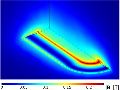
Figure 5. Magnitude of the magnetic flux density in the three symmetry planes of the racetrack coil at a peak current value of 100 A.
Download figure:
Standard image High-resolution image3.2. Modeling and simulation of racetrack coils
Having successfully tested the proposed 3D homogenization with a 2D stack, the aim is set in addressing more complicated problems. Just like infinitely long straight stacks can be modeled in 2D, circular coils can be modeled using an asymmetrical approach, yielding again a 2D model. Therefore, we have chosen to use the proposed homogenization technique for a design that can not be modeled with 2D tools: racetrack coils. Racetrack coils, such as the one shown in figure 3 have two straight and two round sections. Taking advantage of the symmetry planes, only one eighth of the coil was considered for modeling and simulation. Material properties used for simulating the racetrack coil were the same as the ones described for the stack in the previous section. The model considered a 50 turn single racetrack coil wound using 4 mm wide tape with geometrical parameters y0 = 7.5 cm, r1 = 1.5 cm and r2 = 3.5 cm as shown in figure 3. Just like before, a volume fraction, fHTS of 2.5 × 10⁻³ was considered. AC currents at 50 Hz were imposed to the homogenized coil.
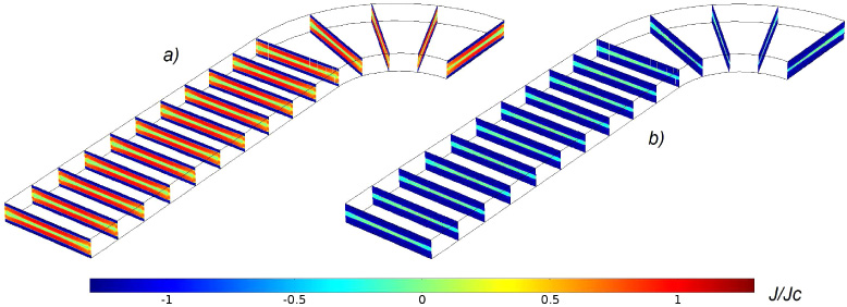
Figure 6. Normalized current density J/Jc(B) at zero crossing (a) and at peak current (b).
Download figure:
Standard image High-resolution image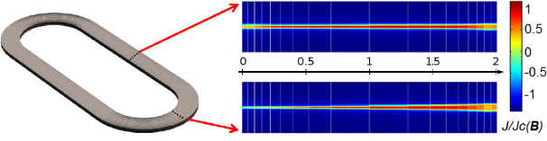
Figure 7. Cross section plot of the normalized current density J/Jc(B) at peak current for the middle of the straight section (top) and the middle of the round section (bottom). The rule in the center of the figure shows the distance (in cm) from the innermost turn of the coil.
Download figure:
Standard image High-resolution imageFigure 5 shows the magnitude of the magnetic flux density at the three symmetry planes of the racetrack coil at a peak current value I of 100 A. The highest magnetic flux density is localized in the inner part of the round section, with a value of 234 mT. In the internal region of the coil, close to the coil's plane, the magnitude of the field is almost uniform with a value of about 10 mT. However, clear differences are observed in both the straight and the round sections of the coil, showing the true three dimensional structure of the model.
Normalized current density distributions J/Jc(B) for both zero crossing (a) and peak current (b) values are shown in figure 6 for the case of a transport current of 100 A. One can note how the homogenization method allows for calculating the current distribution in any place within the stacked tapes. At a first glance, it might seem that the current distributions for each particular case (a) and (b) are rather uniform in the direction of the coil's winding. However as it will be shown that is not necessarily the case. Figure 7 shows the current distributions close to peak value for a transport current of 120 A for two particular locations: the middle of the straight section (top right) and the middle of the round section (bottom right). First, one can note that the current distributions are not symmetric, they have larger critical regions close to the coil's inner side. Secondly, this effect is considerably bigger in the cross section corresponding to the round part. This means that the current is limited by the innermost turn of the coil in the round section. Looking at figure 5 it is easy to see how this relates to the high magnetic flux density in this region of the coil and the fact that a Jc(B) relationship was used.
So far, the model presented here has proved to be useful to calculate magnetic field, current distribution and critical current for a coil under current transport conditions. All of this within a 3D framework.
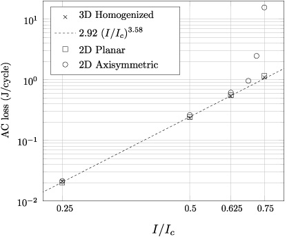
Finally, AC losses were computed for different current amplitudes at 50 Hz for a 50 turn coil made with geometrical parameters y0 = 7.5 cm, r1 = 3.5 cm and r2 = 5.5 cm. These correspond to the coil frame designed as part of the Superwind project at DTU [18]. These estimates are presented in figure 8. The dashed line shows a power law fit of the form Q = 2.92 (I/Ic)3.58. Here, Q is the AC loss in J/cycle, I is the amplitude of the current and Ic the self field critical current of the tape (160 A). A coil of similar size was studied in [7] by means of a 2D planar model. Although the tape characteristics in [7] were different, in said work a similar exponent (3.6351) in the power law fit is reported. For the purpose of comparison, losses were also calculated using both 2D planar and 2D axisymmetric models. The 2D planar model assumed two opposing stacks of 50 tapes each separated by 7 cm. Losses per unit volume were computed and scaled to the volume of the racetrack coil. The 2D axisymmetric model assumed a circular coil of 50 tapes with inner radius of 3.5 cm and outer radius of 5.5 cm. Again, losses per unit volume were computed and scaled to the volume of the racetrack coil.
As shown in figure 8, losses computed using a 2D axisymmetric model provided good agreement only for a limited range of currents but diverged for large I/Ic values. This behavior can be easily understood since for a given current amplitude, the field in the innermost turn of a circular coil is larger than that of its corresponding racetrack coil. Therefore, as the current increases, the innermost turn of the circular coil will saturate faster than that of the racetrack coil, hence yielding much larger losses. On the other hand, the 2D planar model showed good agreement with the 3D homogenization method. For the reasons presented above, this agreement is expected to decrease for larger currents when the effect of the round section of the racetrack coil becomes more important or for coils with smaller straight sections.
4. Conclusions
In this work, a 3D homogenization technique used to model stacks and coils of 2G HTS coated conductors was presented. The method complements a previous work of ours where the 2D case is addressed. Three different ways to impose the integral constraint condition can be chosen and for ease in implementation and computation, a strategy based upon manual discretization of the homogenized bulk was adopted here. Although no zero conductivity perpendicular to the tapes' surface was implemented, to prevent current sharing among the subdomains, highly resistive layers were placed between them, proving to be a good solution.
Figure 8. Computed AC losses with three different models: 3D homogenized, 2D planar and 2D axisymmetric. A power law fit of the form Q = 2.92 (I/Ic)3.58 for the 3D homogenized model is also shown (dashed line).
Download figure:
Standard image High-resolution image
For validation purposes, the 3D homogenization method was tested against a state of the art 2D model considering all the individual conductors and enforcing all the individual currents. Both methods provided a remarkable good agreement over a large range of applied currents and over more than two orders of magnitude for the calculated AC losses.
Finally, racetrack coils which provide a more complicated layout that can not be accurately modeled using 2D methods were considered. The 3D homogenization model allowed us to investigate the magnetic field and the current distributions within the coils for the case of transport current. The method was later used to estimate AC losses in a racetrack coil under transport current at several amplitudes. For comparison, AC losses were also computed using a 2D axisymmetric model, and a 2D planar model. As expected, all models converged in the low current amplitude regime, but the 2D axisymmetric model diverged for large I/Ic values. Remarkably, the 2D planar model showed good agreement with the 3D homogenized model for all the currents studied. However, as explained in the previous section, this agreement is expected to decrease for larger current amplitudes.
Furthermore, the 3D homogenization technique presented here is useful for determining not just the value of the critical current but also its distribution within the coil. This makes this homogenized model a valuable tool for further coil optimization and for considering interactions with other coils or materials and even as part of a larger rotating machinery, where more complicated effects that can not be modeled in 2D take place close to the machine's ends. Other areas of application for this work include transport current studies of non planar coils and other stack-like structures such as cables. Future work will involve testing this model experimentally.
Acknowledgments
This work was funded by the Helmholtz University Young Investigator Group Grant VH-NG-617. The authors would like to acknowledge Dr Nenad Mijatovic (Department of Electrical Engineering at the Technical University of Denmark) for his technical advice regarding the use of an anisotropic resistivity to enforce the current flow in the direction tangential to the tapes' winding. V Zermeno would like to thank Dr Mads P Sørensen (Department of Applied Mathematics at the Technical University of Denmark) for access to his computational resources.