

Abstract
This paper presents a topical review of the current state of the art in modelling the magnetization of bulk superconductors, including both (RE)BCO (where RE = rare earth or Y) and MgB2 materials. Such modelling is a powerful tool to understand the physical mechanisms of their magnetization, to assist in interpretation of experimental results, and to predict the performance of practical bulk superconductor-based devices, which is particularly important as many superconducting applications head towards the commercialization stage of their development in the coming years. In addition to the analytical and numerical techniques currently used by researchers for modelling such materials, the commonly used practical techniques to magnetize bulk superconductors are summarized with a particular focus on pulsed field magnetization (PFM), which is promising as a compact, mobile and relatively inexpensive magnetizing technique. A number of numerical models developed to analyse the issues related to PFM and optimise the technique are described in detail, including understanding the dynamics of the magnetic flux penetration and the influence of material inhomogeneities, thermal properties, pulse duration, magnitude and shape, and the shape of the magnetization coil(s). The effect of externally applied magnetic fields in different configurations on the attenuation of the trapped field is also discussed. A number of novel and hybrid bulk superconductor structures are described, including improved thermal conductivity structures and ferromagnet–superconductor structures, which have been designed to overcome some of the issues related to bulk superconductors and their magnetization and enhance the intrinsic properties of bulk superconductors acting as trapped field magnets. Finally, the use of hollow bulk cylinders/tubes for shielding is analysed.
Export citation and abstract BibTeX RIS
1. Introduction
The ability to generate a permanent, stable magnetic field unsupported by an electromotive force is fundamental to a variety of engineering applications. The magnetization—a useful measure of the ability to generate a magnetic field—of conventional permanent magnets, such as NdFeB and SmCo, is independent of sample volume and is therefore limited by the material properties of the permanent magnet. Bulk superconducting materials, on the other hand, trap magnetic flux via the generation of macroscopic electrical currents, which leads directly to an increase in magnetization with sample volume. This, in turn, potentially overcomes this fundamental limit in the size of field generated by conventional permanent magnets.
Bulk superconductors, acting as trapped field magnets (TFMs), can trap magnetic fields of magnitude over ten times higher than the maximum field produced by conventional magnets, which is limited practically to rather less than 2 T, less than the saturation magnetization of iron [1]. Indeed, it has been shown that (RE)BCO (where RE = rare earth or Y) bulk superconductors can trap fields greater than 17 T—the long-standing world record field generated by an arrangement of two bulk superconductors of 17.24 T at 29 K [2] was recently exceeded by 17.6 T at 26 K in [3]. Additionally, bulk superconductors can exhibit Jcs of 5 × 10⁴ A cm−2 at 1 T and 77 K (the boiling point of liquid nitrogen), resulting typically in trapped fields of up to between 1 and 1.5 T for YBCO and greater than 2 T for (RE)BCO at this technologically important temperature, with 3 T the highest trapped field at 77 K so far [4]. It should be noted that the values quoted are with respect to standard, non-irradiated YBCO and (RE)BCO samples, but neutron-irradiated, radioactive YBCO samples have exhibited higher Jc values [5, 6] and trapped fields over 2 T at 77 K [5–8].
Another superconductor that shows promise in bulk form as TFMs is MgB2. MgB2 was first reported in [9] and although the transition temperature for this material is low (39 K), which requires a lower operating temperature (15–20 K) and more complex cryogenic system than that for (RE)BCO bulks, the material is cheaper, lighter weight and has a more homogeneous Jc distribution. Furthermore, the relative ease of fabrication of MgB2 materials, as well as their long coherence length [10], lower anisotropy and strongly linked supercurrent flow in untextured polycrystalline samples [11, 12], has enabled a number of different processing techniques to be developed. Significant improvements continue to be made in terms of in-field Jc and trapped field capability:
- 5.4 T at 12 K was achieved with a single 20 mm diameter MgB2 bulk fabricated by hot-pressing ball-milled Mg and B powders [13];
- 4 T at 11 K and 3 T at 20 K with a pair of 30 mm diameter MgB2 bulks fabricated by conventional sintering [14];
- 3.6 T at 13.2 K and 2.8 T at 20 K with a single 38 mm diameter Ti-doped MgB2 bulk fabricated by the hot isostatic pressing method [15];
- 3.14 T at 17.5 K with a pair of 25 mm diameter MgB2 bulks fabricated by uniaxial hot pressing [16];
- 1.5 T at 16.4 K with a 30 mm diameter MgB2 bulk fabricated by a capsule method [17]; and
- 1.3 T at 15 K with a 55 mm diameter sample (with a 6 mm central hole) fabricated by the reactive Mg liquid infiltration technique [18].
There has also been some recent work on the possibility of utilizing stacks of (RE)BCO tapes as pseudo-bulk TFMs [19–23]: up to 7.34 T has been trapped at 4.2 K using a stack of 120 layers of 12 mm square high-temperature superconducting (HTS) coated conductor [19].
As a result, there is great interest in using these materials as TFMs in a number of engineering applications, including magnetic bearings, energy storage flywheels, magnetic resonance imaging, magnetic separation and rotating machines [24–26]. Significantly, the higher magnetic loading in rotating machines would provide an increased torque/power density, resulting potentially in a machine that is smaller and lighter in weight than conventional devices of the same rating [27, 28]. However, investigating and predicting the magnetization of these technologically important materials and developing practical magnetizing techniques is crucial to using them as TFMs in applications of these types.
A number of analytical and numerical models have been proposed for simulating the properties of bulk superconducting materials and modelling is a powerful tool to understand the physical mechanisms of their magnetization, to reproduce and assist in the interpretation of experimental results, and predict the performance of practical bulk superconductor-based devices. In addition, in the case of bulk superconductors, such numerical modelling can be used to predict and propose new magnetizing techniques, which is more difficult to achieve experimentally.
Analytical models can be easier, faster and more accurate compared to numerical methods, such as those based on the finite element method (FEM), but are limited to specific geometries and simplified assumptions [29]. Numerical models can overcome some of these limitations and simulate more complex geometries and situations, but this comes at the expense of increased computational requirements, more complex software implementation and longer computational times [30]. An example is the multi-physical numerical model required for the pulsed field magnetization (PFM) of a bulk superconductor, which requires both electromagnetic and thermal considerations over a very short time scale.
Numerical modelling is a particularly important and cost-effective method to guide both superconducting material processing and practical device design as many superconducting applications head towards the commercialization stage of their development in the coming years. Therefore, this paper presents a topical review of the current state of the art in modelling the magnetization of bulk superconductors, including both (RE)BCO and MgB2 materials. In addition to the analytical and numerical techniques currently used by researchers for modelling, the paper also reviews some of the experimental results that support the modelling results, and the implications of these for designing practical trapped flux-type devices, such as bearings and electric machines.
In section 2, a simple analytical method to calculate the trapped field of a bulk superconductor based on the Bean critical state model is presented, as well as an overview of analytical and numerical techniques used to model superconducting materials in general. In section 3, the commonly used practical magnetization techniques are summarized with a particular focus on the PFM technique, including understanding the role of inhomogeneities, multi-pulse techniques and pulse coil configurations, on the flux dynamics of the magnetization process. In section 4, the effect of externally applied magnetic fields in different configurations on the attenuation of the trapped field is discussed, and in section 5, a number of novel and hybrid bulk superconductor structures are described, including improving the thermal properties of bulk superconductors, ferromagnet–superconductor structures, and hollow bulk cylinders/tubes for shielding. Finally, the paper is concluded in section 6 with a view towards the future and the remaining challenges in this active field of research.
2. Calculating trapped fields
2.1. Analytical techniques
Based on the critical state model presented by Bean [31, 32], the peak trapped magnetic flux density, Btrap, at the centre of the top surface of a single-grain bulk superconductor, oriented with its thickness parallel to the c-axis, due to an induced, persistent supercurrent is given in its simplest form by

where μ0 is the permeability of free space, Jc is the critical current density of the superconducting material, and a is the sample radius. k is a correction factor to the simple Bean (slab) approximation due to the finite thickness, t, of a disc-shaped bulk superconductor sample, based on application of the Biot–Savart law, given by [16, 17]:

A more general formula for the field at any height (z) above a superconducting disc of radius a and thickness t was presented in [17, 33–35]:
Equation (1) implies two main approaches for improving the field trapping ability of a bulk superconductor: (1) by enhancing the critical current density through improved flux pinning and increased sample homogeneity, and (2) by increasing the sample size. In addition to these factors, the performance of a bulk superconductor can be limited by strong Lorentz forces that result in large mechanical stresses on the material that can induce cracks in the sample and severely degrade the trapped field [3], and a heat exchange rate with the cryogenic fluid or cooling apparatus that is too low can result in significant temperature rises in the material [36].
An overview of analytical methods and formulae for modelling HTS materials is presented in [37], but this work focuses chiefly on thin strips and stacks thereof, and is therefore most applicable to HTS wires, cables and related devices. Analytical expressions have been derived for the current and field distributions using the Bean assumption (constant Jc) for an infinitely thin disc for the static non-linear case [38], as well as for perpendicular time-varying periodic external magnetic fields [39]. Numerical solutions also exist for superconducting discs of finite thickness [40–43], and in [44], Brandt calculated the electromagnetic response of a disc of finite thickness in a perpendicular time-varying magnetic field, extending his work on a thin strip in [45]. Whilst analytical methods are easier and faster to implement compared to numerical methods, they are limited to specific geometries and simplified, homogeneous assumptions regarding the superconductor's electromagnetic and thermal behaviours. Such methods are usually based on the critical state model (constant Jc and no frequency dependence) and can only deal with simple, uniform fields. Numerical methods, which are introduced in the following section, can be used model more complex, practical situations, for arbitrary geometries and applied fields, and where the superconductor's behaviour can vary depending on a number of different variables.
2.2. Numerical techniques
There exist a number of different numerical techniques that have been applied variously to the modelling of superconducting materials [30, 46], including the finite difference method [47], the combined sand-pile/Biot–Savart method [48–51], the Fourier Transform method [29], minimization or variational techniques [52–58] and FEM. In general, FEM techniques are the most commonly used and developed methods, and these can be applied to superconducting material problems using a variety of formulations [30, 59, 60]: namely the A–V [61–63], T–Ω [64–66], H [67–78] and E [59, 79–81] formulations, and Campbell's equation [63, 82]. Maxwell's equations can be written in each of these formulations and these formulations are equivalent in principle, but the solutions of the corresponding partial differential equations can be very different [83]. It should be noted that many of these examples are applied to geometries other than superconducting discs in the above references, but in the remainder of this paper, recent applications of such numerical techniques related specifically to bulk superconductor magnetization are highlighted in more detail.
3. Investigating practical magnetization techniques
There are three magnetization techniques for magnetizing a bulk superconductor that are in common use: zero field cooling (ZFC), field cooling (FC) and PFM. The basic principles behind the ZFC and FC techniques are shown in figure 1 using the Bean model [31, 32] approximation, which assumes a constant Jc. The field, Hp, in figure 1 is called the full penetration field and is directly related to equation (1) for a disc of finite thickness (for an infinitely long slab, Hp = Jca, where a is the half-width of the slab).

Figure 1. Zero field cooling (ZFC) and field cooling (FC) bulk superconductor magnetization techniques using the Bean model [31, 32] approximation. Reproduced with permission from [84]. For ZFC (left), a magnetic field equal to the full penetration field, Hp, is applied to a pre-cooled sample (top panel), which is increased to 2Hp (middle panel), and then the field is removed, trapping a field H0 = Hp (bottom panel). For FC (right), a magnetic field H0 is applied to a sample above its critical temperature Tc (top panel), which is then cooled below Tc and the field is slowly removed (middle panel; where the applied field is reduced to 0.5H0), trapping a field equal to the applied field H0 (bottom panel).
Download figure:
Standard image High-resolution imageIn ZFC, the superconductor is cooled below its critical temperature, Tc, prior to the application of a large magnetic field, typically of several tesla. A magnetic field of comparatively lower magnitude is applied in the FC process to a superconductor at a temperature above Tc, which is then cooled below Tc. In either case, to trap the maximum possible field corresponding to the sample's flux-trapping ability, the magnitude of the applied field needs to be at least Btrap (at least Btrap in FC; 2Btrap in ZFC), assuming Bean's model [31, 32].
The ZFC and FC magnetization techniques invariably require large magnetizing coils, which is impractical for most applications of these materials. The PFM technique is similar to ZFC, except that the large magnetic field is applied via a pulse on the order of milliseconds, rather than ramped up and down slowly over a period of many minutes or even hours. Achieving reliable, in situ magnetization is crucial to producing a competitive and compact machine design in trapped flux-type rotating machines, and the PFM technique shows great promise as a compact, mobile and relatively inexpensive magnetization technique for the magnetization of these and other TFM-based devices.
3.1. PFM technique
One significant issue with the PFM technique is that the trapped field produced is generally smaller than that of ZFC or FC, particularly at lower operating temperatures, due to the large temperature rise ΔT associated with the rapid dynamic movement of the magnetic flux in the interior of the superconductor during the PFM process [85]. However, at higher operating temperatures (closer to Tc, such as 77 K) fields have been trapped close to that of FC [8, 35, 86–88].
Compared with the record trapped field (17.6 T at 26 K), which was generated by the slower FC technique, it has been experimentally confirmed that the trapped field by PFM cannot exceed the trapped field by FC. Accordingly, the record trapped field produced by PFM is only 5.2 T at 29 K [89]. Therefore, it is important to understand the flux dynamics when magnetizing a bulk superconductor using the PFM technique in order to achieve an optimum trapped field profile and to investigate how these results translate into a practical magnetizing technique for applications such as trapped flux-type superconducting electric machines [90].
There are many experimental results published in the literature and the following issues have been confirmed for the PFM technique:
- The temperature rise increases with increasing magnitude of the applied pulsed magnetic field and with decreasing operating temperature for an identically applied field, which comes from the stronger magnetic forces and the decreased heat capacity of the bulk at lower temperatures, respectively [91];
- The temperature rise during PFM increases for increased Jc values of the bulk, which is strongly related to the pinning force, Fp [92];
- The temperature rise, which arises due to the pinning loss and the viscous loss [92, 93] takes place adiabatically during PFM, because a large amount of the heat generation takes place instantaneously and the cooling power is finitely limited. The low thermal conductivity of the bulk also seriously affects the thermal and electromagnetic responses; and
- The experimental setup, including the thermal pathways between the cooling system (either cryogenic fluid or cryocooler) and the sample, and the type and form of the epoxy impregnation of the bulk (if present), can heavily influence the resultant magnetization [91].
All of these results could be clarified by measuring the maximum temperature, Tmax, of the bulk surface after the application of the pulsed field. Because of significant temperature rises and the inverse relationship between Jc and the temperature, T, the bulk cannot be magnetized to its highest potential, but also the bulk is not irreversibly damaged by PFM, as far as has been observed thus far.
3.2. Understanding flux dynamics
The most important characteristic of a superconductor for any practical superconducting device is the maximum electrical transport current density it can maintain without resistance, or its critical current density, Jc [94]. Therefore, one of the most crucial aspects of superconducting bulk material and device modelling is providing accurate data for the in-field performance, including anisotropy, of Jc at different temperatures, i.e., Jc(B, T). If this behaviour is known in detail, it is possible to accurately predict the magnitude and shape of the trapped field profile and the flux dynamics of the magnetization process.
The results of the numerical simulation strongly depend on Jc(B, T) and it is necessary to adjust this relationship precisely to the experimentally obtained one. Kim [95] and Anderson [96] showed that the critical current in 'hard,' or type II, superconductors (for example, HTS materials) exhibit a strong dependence on temperature, as well as local magnetic field, which is expressed in the following, generalized empirical relationship:

where Jc is the local critical current density, B is the magnitude of the local field, B0 and β are material-dependent constants that can vary with temperature and Jc0 is the magnitude of critical current density when the local field is zero. Jc0 can be considered a constant value or as a temperature-dependent function Jc0(T) if thermal considerations are necessary. Equation (4) has been applied variously to bulk superconductors in [97–102]. The material-dependent constants can be estimated via the trapped field profile of the bulk (for example, [97]) or by measurements of the magnetic moment hysteresis (m-H) loops of sub-specimens taken from the bulk (for example, [16, 103, 49]) at different temperatures.
Equation (4) does require some modification to include the so-called 'fish-tail' or 'peak' effect in some (RE)BCO superconductors, where there is a 'second peak anomaly' found in some bulk samples [26, 104, 105]. An exponential fitting function has also been proposed to represent such behaviour [106]. It also requires some modification in the case of HTS wire where there is a dependence of Jc on both the magnitude and orientation of the magnetic field seen by the superconductor [107]. Furthermore, as described in section 3.2.2, a different equation is needed to represent the behaviour of MgB2 materials because there is no peak effect and there is a drastic suppression of Jc in the presence of a magnetic field.
During PFM, since there are localized (and sometimes large) changes in temperature and magnetic field, it is important to introduce a precise relationship for Jc(B, T). This is largely due to the role of inhomogeneities in the superconductor and this is the subject of the next section.
3.2.1. Inhomogeneities in (RE)BCO bulk superconductors
Inhomogeneities occur during the growth process of c-axis seeded, single grain (RE)BCO bulk superconductors, resulting in the formation of growth section regions (GSRs) and growth sector boundaries (GSBs), as shown in figure 2, with a higher Jc for the GSBs in comparison with the GSRs [98, 108–110]. These play a significant role in the magnetization of these materials, particularly for the PFM technique, where they can affect the magnitude and shape of the trapped field and the maximum temperature rise, and different results are observed in comparison to FC and ZFC, particularly for lower applied fields [111]. Jc can also vary as a function of position in a sample: generally a lower Jc is found at the edge with respect to the centre and at the bottom with respect to the top [26, 33, 112]. In general, and for most standard cases, the equation for Jc is relatively easy to introduce into a model once the dependence on magnetic field, temperature and position is known [107].

Figure 2. YBCO (left) and GdBCO (right) bulk superconductor samples. The growth sector boundaries (GSBs) are shown for each sample. © IOP Publishing. Reproduced by permission of IOP Publishing from [90]. All rights reserved.
Download figure:
Standard image High-resolution imageThe role of inhomogeneities in the PFM process has been analysed numerically in [90, 98, 99, 113]. In [90], a model is presented based on the three-dimensional (3D) FEM H-formulation [75, 77, 90, 114], but in principle, as described in section 2.2, other formulations are interchangable. There also exist two-dimensional (2D) infinitely long [69, 70, 72–74, 115] and 2D axisymmetric [78, 116] versions of the H-formulation for the reader's reference.
In the 3D H-formulation, the governing equations are derived from Maxwell's equations—namely, Faraday's (5) and Ampere's (6) laws:


where H = [Hx, Hy, Hz] represents the magnetic field components, J = [Jx, Jy, Jz] represents the current density and E = [Ex, Ey, Ez] represents the electric field components. μ0 is the permeability of free space and for the superconducting and air sub-domains, the relative permeability is simply μr = 1. However, this formulation also allows the introduction of magnetic subdomains into the model by introducing a relative permeability μr ≠ 1, which may be not constant, but varies with magnetic field, i.e. μr(H), where H is the magnitude of the magnetic field [73, 74, 76].
It is assumed that the electric field E is parallel to the current density J [69, 72, 73, 75] such that J = σE or E = ρJ, where σ and ρ are the conductivity and resistivity, respectively, and both highly non-linear. The electrical behaviour of the superconducting material is modelled by the E-J power law [117, 118], where E is proportional to Jn, as shown in (7).

where E0 = 1 μV cm−1 is the characteristic electric field and n is an appropriate value for the superconductor. For HTS materials, n usually varies between 5 (strong flux creep) and 50 (limiting value between HTS and LTS materials) [60, 61, 73], and for n > 20, it becomes a good approximation of Bean's critical state model, for which n → ∞. In the case of [90], n = 21.
In order to simulate the thermal effects of an external field on the trapped field, a thermally-isolated model of a bulk superconductor can be used to simulate liquid nitrogen cooling [90] or a cold head and vacuum [78, 103, 113] can be included in the model with or without a spacing plate between the cold head and sample.
The following thermal transient equation can be used in this model to model the thermal properties of the system:

where ρ, C and κ are the mass density, specific heat and thermal conductivity of the bulk sample, respectively.
In the simulation, suitable assumptions must be made regarding the specific heat and thermal conductivity for both MgB2 and (RE)BCO bulks. Figure 3 shows a comparison of the typical measured specific heat [119, 120] and thermal conductivity [121, 122] for MgB2 and (RE)BCO bulk superconductors. At the typical operating temperature for each bulk (Ts = 15 K for MgB2 and Ts = 40 K for (RE)BCO), the specific heat per unit volume of MgB2 is three orders of magnitude smaller and the thermal conductivity is about three times larger, compared with those of the (RE)BCO bulk. These results suggest that a larger temperature rise is expected in the MgB2 bulk under identical heat generation, but the generated heat diffuses faster.

Figure 3. Comparison for MgB2 and (RE)BCO bulk superconductors of (a) specific heat and (b) thermal conductivity.
Download figure:
Standard image High-resolution imageThe heat source Q in the thermal model is derived from the product of the electric field and current density throughout the bulk superconductor, defined as Q = E · J, where  and
and  describing the adiabatic condition where the temperature rise comes from the local dissipation due to magnetic flux motion.
Jc0(T) is the temperature dependent critical current density of the superconductor, given by:

where α is the critical current density extrapolated to T = 0 K, Tc ≈ 90–92 K in the case of a (RE)BCO bulk superconductor, and m = 1.5 [78, 90, 103, 123] or 2 [124, 125]. There are also examples where a linear Jc(T) relationship is assumed ([99, 101] and see sections 3.3.1 and 4). It is common practice for modellers to use an equation, such as equation (4) (or equation (19) for MgB2 in section 3.2.2), to fit the measured experimental data at a particular operating temperature, Top, and then use equation (9) to represent the thermal behaviour of the superconductor for variations in temperature around Top, which assumes that the material-dependent parameters in equation (4) do not vary significantly for such temperature variations.
Although there can be some temperature rise during the slower FC and ZFC magnetization techniques [126], the effects are not as pronounced as for PFM and generally, for a slow enough applied field, an electromagnetic model is usually sufficient.
An external magnetic field is usually applied to the bulk along the z-axis, perpendicular to the top surface of the sample, by setting appropriate boundary conditions in the model. It is also possible to introduce the magnetizing coil itself as a separate entity in the model to investigate the influence of the coil type and shape on the trapped field, e.g., solenoid [78, 98], vortex [127] and split [100] coils, which is described in more detail in section 3.3.2.
The applied field can take a variety of forms—sinusoidal, trapezoidal, triangular and so on—but the following equation is often used in the case of PFM to represent the practical experimental waveform observed when discharging capacitors through a magnetizing coil [90, 103]:

where τ is an appropriate value for the rise time of the pulse.
In [90], the trapped field distribution and maximum temperature rise for an applied pulsed magnetic field is compared for a completely homogeneous bulk superconducting sample with an ab-plane Jc of 1 × 10⁸ A m−2 and an inhomogeneous sample with the same average Jc, but with Jc varying as a cosine function in the ab-plane [75], as shown in figure 4. The thick, dashed lines represent the GSBs. Other than this spatial variation of Jc, a constant Jc approximation is considered for the in-field behaviour for the purposes of comparing the role a varying Jc between GSBs and GSRs plays on the magnetization of the sample, but in theory, a field- or position-dependent Jc may be introduced into the model. In this case, there are two models:
- (1)A homogeneous bulk sample with an average Jc of 1 × 10⁸ A m−2
- (2)An inhomogeneous bulk sample with Jc of 1 × 10⁸ A m−2 with x–y spatial variation ± 0.1 × 10⁸ A m−2
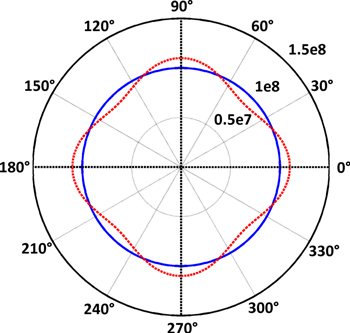
Figure 4. Spatial distribution of the critical current density Jc(θ) in the ab-plane (xy-plane) of the bulk superconductor for the two cases being analysed (homogeneous and inhomogeneous). © IOP Publishing. Reproduced by permission of IOP Publishing from [90]. All rights reserved.
Download figure:
Standard image High-resolution imageConsistent with the experimental results presented in [90], the inhomogeneous Jc distribution results in a distorted trapped field profile, where flux is trapped preferentially in regions of stronger pinning (higher Jc). Flux does enter the regions of weak pinning GSRs more easily, but flux can also leave these regions more easily, and localized heating acts to reduce Jc and pinning strength further. The homogeneous model traps a larger overall magnetic field and a lower temperature rise is observed in comparison to the inhomogeneous one [90].
This kind of modelling framework allows the presence of the various inhomogeneities that arise during the processing of (RE)BCO bulk superconductors to be considered, including inhomogeneous Jc distributions (between top and bottom regions or between the seed and outer edge of the bulk [33, 128], for example) and the presence of current limiting grain boundaries and cracks. It can also be used to assist optimization of processing techniques, such as samples with novel seed arrangements [129–133], as well as PFM techniques and coil design, for practical bulk superconductor applications.
3.2.2. Homogeneous MgB2 bulk superconductors
In contrast to the Jc distribution of (RE)BCO bulk superconductors, bulk MgB2 has a more homogeneous Jc distribution, making studies on such systems somewhat easier because simplified assumptions regarding the geometry and Jc distribution can be made. Such studies can also assist in understanding more deeply the physics of (RE)BCO bulk superconductor magnetization.
In [126], a 2D axisymmetric model is implemented using the A–V formulation in combination with measured critical current density Jc(B, T) profiles and the experimental results for MgB2 bulk samples magnetized by the FC technique were reproduced well. The value of the peak trapped magnetic field Btrap and the trapped field profile can be estimated precisely for bulks of any shape, for various applied fields and operating temperatures.
In the A-V formulation, the magnetic vector potential A is defined by


Since

we have

where V is an arbitrary scalar and can be considered the potential due to electrostatic charges from (12). This formulation has two main advantages: the contour of A directly gives the magnetic lines of force in 2D Cartesian geometry and there are a large number of problems in which A is scalar, requiring only one variable, instead of three, to describe the vector field B [46].
Using Ampere's law (6), we obtain

Since  we also obtain

Based on this formulation and the relationships described thus far, the following electromagnetic and thermal equations were derived in [126] for a 2D axisymmetric system representing a cylindrical bulk superconducting disc.


This model also includes the magnetizing coil, instead of uniform boundary conditions representing the applied field, as shown in figure 5. In (17), J0 is the 'forced' coil current density and J is the induced superconducting current density, and (18) is the 2D axisymmetric form of (8). The heat generated in the bulk, Q, is again calculated as Q = E · J.
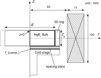
Figure 5. Schematic view of the experimental setup and the basis for the numerical model of bulk MgB2 superconducting discs magnetized by FC presented in [126]. © IOP Publishing. Reproduced by permission of IOP Publishing. All rights reserved.
Download figure:
Standard image High-resolution imageAs described in section 3.2, a suitable approximation for the Jc(B, T) characteristics of the bulk is required and the homogeneity of the MgB2 bulk means a relatively smaller number of sub-specimens are required for data fitting, especially with respect to varying position, in comparison to (RE)BCO bulks. In [126], Jc(B, T) for each MgB2 bulk at 10 K and 20 K was fitted, as shown in figure 6, using the following relation [134]:

where B0 and γ are the fitting parameters for each temperature. In addition, the E-J power law (7) with n = 100 and the Jc0(T) relationship given by (9) are used with Tc = 39 K.

Figure 6. Estimated Jc(B) characteristics for both MgB2 bulks in [126] at 10 K and 20 K. The solid lines show the fitting curves used in the simulation. © IOP Publishing. Reproduced by permission of IOP Publishing. All rights reserved.
Download figure:
Standard image High-resolution imageThe modelling results reproduce the experimental results well, as shown in figure 7, and the slight difference between the two may be explained by slight inhomogeneities in the Jc and/or temperature distributions in the bulk. When the applied magnetic field is removed, a bell-shaped trapped field profile materializes (see figure 7), which may originate from the steep magnetic field dependence of Jc. These results are in contrast with those using Bean's critical state model described in sections 2 and 3, highlighting the limitations of such a model, which results in a conical profile. It also highlights the necessity of accurate Jc(B, T) data for modelling bulk superconducting magnetization. It was also found that increasing the diameter of the bulk is not an effective route to improving the peak trapped field, but efforts should focus on improving the Jc(B) properties.

Figure 7. (a) Simulation results for the trapped field Bz (z = 0 mm) at 10 and 20 K for each MgB2 bulk. The solid lines show the experimental results. (b) Cross-sections of the trapped field profiles at 20 K for each bulk at z = 0 (bulk surface) and 3 mm [126]. © IOP Publishing. Reproduced by permission of IOP Publishing. All rights reserved.
Download figure:
Standard image High-resolution image3.3. Other considerations for magnetization
3.3.1. Multi-pulse techniques
There are many considerations and variables for the PFM technique, including the pulse duration, magnitude and shape, the temperature(s) at which the pulse is applied, the number of pulses and the shape and type of the magnetizing coil(s), and some novel PFM techniques have been proposed to improve the trapped field because the trapped field from a single pulse is often a fraction of the sample's trapped field capability as indicated by FC magnetization [90, 125]. For example, multi-magnetic pulse techniques, such as an iteratively magnetizing pulsed-field method with reducing amplitude [135] and a multi-pulse technique with step-wise cooling (MPSC) [136, 137]. The record achievement of 5.2 T at 29 K using PFM was carried out using a modified MPSC (MMPSC) technique [89, 93].
In [138], the authors use a 2D axisymmetric model, based on the critical state model and a Jc(B) relation given by the Kim model, to reproduce the experimentally observed trapped field profile for a bulk that is magnetized further by a second pulsed field again after being partially magnetized by an initial pulsed field. Re-pulsing the bulk sample with temperature control is found to be effective for increasing the magnetization for a partially magnetized sample.
In [139], the H-formulation presented in [68] is extended to the numerical analysis of the MMPSC technique to compare magnetization from a successive magnetic pulse application (SPA) method and evaluate the underlying physical mechanisms governing the process. For this qualitative analysis, the model considers an infinitely long cylinder of width the same as the diameter of the sample, an E-J power law (7), a linear relationship for Jc(T) and adiabatic conditions for the thermal analysis. For SPA, several pulsed fields of similar magnitude are applied to a sample, which is held at a constant cooling temperature. For MMPSC, pulsed fields of relatively smaller magnitude are applied initially to a sample that is cooled to a relatively higher temperature, and then the sample is cooled further and subject to pulses of larger magnitude. A schematic diagram of these two processes is shown in figure 8.
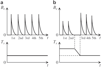
Figure 8. Schematic diagrams of the profiles of external applied magnetic field and cooling temperature for PFM with (a) the SPA method and (b) the MMPSC method. Reprinted from [139], copyright 2008, with permission from Elsevier.
Download figure:
Standard image High-resolution imageThe numerical results for a single pulse agree qualitatively with experimental PFM results whereby increasing the magnitude of the applied pulse after full magnetization results in an increasing reduction in trapped field [90, 92, 103, 110]. The SPA multi-pulse technique results in a trapped field that saturates with successive pulses, with no significant additional flux trapped for further pulses. The MMPSC technique, on the other hand, results in a higher trapped field after a few pulses, but a similar temperature rise in the sample in comparison to SPA. The numerical simulation confirmed the advantage of the MMPSC technique and the experimental results in [140].
In [141], the authors applied the numerical technique in [103] to evaluate the MMPSC technique. Extending the results above [139], the real cylindrical geometry of the sample was modelled and the time evolution and position dependence of the magnetic field and temperature were reported, in order to further understand the flux dynamics and temperature propagation when using MMPSC. It was found, in particular, that the increase in trapped field after the second pulse could be explained by a reduction in temperature rise from the pulse due to the flux already trapped from the initial pulse. Such numerical analyses can assist in developing and optimizing novel magnetizing techniques in terms of the number of pulses, temperature profiles and so on, in order to maximize the trapped field.
3.3.2. Different magnetization coil arrangements
Another important practical consideration for the magnetization of bulk superconductors is the shape and type of the magnetizing coil(s). Solenoid coils are most commonly used for fundamental measurements on such materials, but a number of other coil structures have been investigated to improve the performance of the magnetization process and with consideration to magnetizing bulk superconductors practically in TFM-based applications.
Split coil magnetization [100, 125, 142, 143], where a pair of magnetizing coils are placed above and below the bulk, instead of around the periphery of the bulk (solenoid coil), has a number of merits: heat generated in the sample may be removed along the sample's ab-plane, which has a thermal conductivity an order of magnitude higher than along the c-axis [103]; coils smaller than the diameter of the sample itself can be used, which allows for a more compact magnetization structure; and it has been reported that such coils can increase the total trapped flux significantly [144]. A special type of split coil arrangement, known as vortex-type coils [145–149], has also been developed and implemented in an axial gap-type HTS synchronous machine [146, 150] to magnetize a rotor utilizing bulks as TFMs.
In [151, 152], flat racetrack-shaped magnetizing coils were developed in order to use PFM to magnetize an array of bulk superconductors as field poles in a radial flux-type HTS synchronous motor. It may also be possible to use superconducting materials of different Tcs and a dual cooling system to develop an in situ FC magnetization process for YBCO bulk plates using the superconducting stator coils of an electric machine, as described in [153].
Numerical simulations of the PFM process using split- and vortex-type magnetization coils were presented in [100] and [127], respectively. Figure 9 shows the geometric configuration for a reference solenoid coil and two types of vortex coils analysed in [127]: an S-coil, where the outer diameter of the coil is smaller than the bulk diameter, and an L-coil, where the coil is larger than the bulk diameter. The simulation results support many of the observed experimental results and suggest that the maximum trapped field can be larger for lower applied fields in comparison to a solenoid coil. Figure 10 shows the trapped field and maximum temperature rise at the centre of the bulk surface for the three coils and the results are compared with the experimental results of [154]. Both [100, 127] show that with split/vortex coils, the magnetizing mechanism is different in that, instead of flux penetrating from the periphery (or edge) of the bulk, the flux penetrates from the top/bottom surfaces. The process is most effective with coils smaller in diameter than the bulk. Furthermore, it is shown that there is significantly less heat generated when pulsing with vortex coils, and a longer pulse application time, which is recognized to be important in the case of solenoid-type coils [103], is not necessary for such coils. These results are promising for reducing the size of the array of capacitors required for PFM systems.

Figure 9. Geometric configuration for modelling vortex-type coil magnetization of bulk superconductors (a) vortex S-coil, (b) vortex L-coil and (c) solenoid coil. © IOP Publishing. Reproduced by permission of IOP Publishing from [127]. All rights reserved.
Download figure:
Standard image High-resolution image
Figure 10. (a) Trapped field Bz (r = 0) and (b) maximum temperature Tmax (r = 0) at the centre of the bulk surface as a function of applied field Bex using the three coils (vortex S-coil, vortex L-coil and solenoid coil) shown in figure 9. (c) Reported experimental results by Ida et al in [154]. © IOP Publishing. Reproduced by permission of IOP Publishing from [127]. All rights reserved.
Download figure:
Standard image High-resolution imageSuch numerical analyses can assist in optimizing the shape and type of the magnetizing coil(s) to take into account practical considerations for TFM-based devices that require a compact and efficient magnetization technique that also maximizes the trapped field.
4. AC losses and demagnetization effects
It is well known that, at a finite temperature, thermal energy can allow flux lines inside a superconductor to move from one pinning point to another due to the Lorentz force arising from the interaction between the current and flux density [155]. This is known as flux creep [156–158] and leads to a slow, logarithmic decay (log t) of trapped field in a bulk superconductor over time [33]. Hence, a consequence of the finite n value in the power law relationship, given by (7), is the relaxation of the magnetization due to flux creep, which is more suitable to describe the behaviour of HTS materials than true critical state models [115]. Because of the logarithmic time dependence of the trapped field, the decay in trapped field is large immediately after magnetization, so it is important experimentally to know the time at which the trapped field measurement was taken, which can be a cause of mismatch between the experimental results and numerical simulation.
When a magnetized bulk superconductor, magnetized parallel to the c-axis, is subjected to an external magnetic field that may be parallel or perpendicular (the so-called 'crossed field effect' [22, 115, 159, 160]) to its pre-magnetization, it can suffer a partial or full decay of the trapped field [115], which is also known as the 'collapse of the magnetic moment' [159]. This can significantly reduce the bulk's potential as a TFM and can result in the failure of such bulk magnets in practical applications [116]. In a trapped flux-type superconducting synchronous machine [150, 161–163], for example, where the HTS bulks act as TFMs, bulk (RE)BCO samples can be employed in the rotor and magnetized parallel to the c-axis before the machine rotates. In these rotating machines, the position of bulk sample is expected to follow continuously the rotating field generated by the three phase stator/armature winding. In practice, however, any ripples in the applied torque on the shaft may cause the trapped field to become misaligned with the direction of stator over a short time period [164]. Due to vibration, lateral movement or an inhomogeneous stator field, an HTS bulk in a practical device may experience periodic variation of the external applied field [165, 166]. Although the most severe influence of external ac field arises when the field direction is perpendicular to the initial trapped field of HTS bulk [115, 167], the trapped field can decay or even be erased by the influence of an external time-varying field parallel to the direction of trapped field even when the amplitude is much smaller than the trapped magnetic field [167–169].
In [115], the properties of bulk (RE)BCO samples were analysed numerically in the crossed field configuration, i.e., the externally applied field is orthogonal to the magnetization of the superconductor, using the 2D infinitely long H-formulation. The numerical model qualitatively reproduced the observed experimental results, and indicated that the suppression of magnetization comes predominately from the redistribution of the supercurrent in the bulk, leading to a rotation of the plane of symmetry of the current distribution such that it opposes the variation in magnetic flux imposed by the external field. If a field-dependent Jc(B) is included in the model, then the effect is increased whereby the magnitude of Jc reduces. In [159], a similar model is used to analyse the remagnetization process of a (RE)BCO sample partially demagnetized by an orthogonal field by applying a small magnetic field between transverse cycles that is parallel to the original magnetization. Such models allow analysis of the dynamics of the complex supercurrent flowing in the bulk, as shown in figure 11, for various combinations of applied external fields [159].
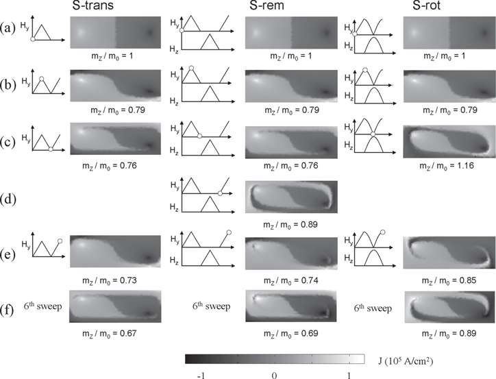
Figure 11. Modelled data of the complex current density distributions Jx(y, z) within the cross-section of the bulk sample at selected times during each of three cycles of an applied magnetic field of magnitude Hmax = 0.5Hp. The magnetic moment normalized to the initial value, mz/m0, is also given below each current distribution. More details on the configuration of the applied fields can be found in [159]. © IOP Publishing. Reproduced by permission of IOP Publishing. All rights reserved.
Download figure:
Standard image High-resolution imageIn addition to the attenuation of trapped field in bulk superconductors caused by flux creep and shielding current redistribution within the HTS bulks, careful consideration must also be given to changes in the thermal properties related to heat generated in the bulk. Similar to the considerations for PFM (and to a lesser degree for FC and ZFC) described earlier in this section, there is heat generated in the sample due to the penetration of an external time-varying field into the bulk, resulting in a temperature rise [170]. The experimentally observed temperature rise due to an AC field has been described successfully qualitatively using a linear temperature dependence Jc(T) with Bean's model [169] or a field-dependent Jc(B) and n(B) [101] and assuming a constant convective heat transfer between the sample and coolant [171]. In [172], analytical expressions were derived for the steady-state (equilibrium) temperature of the bulk sample subject to an ac field based on Bean's model for an infinite slab and an infinite cylinder with a constant heat transfer coefficient. By defining two specific threshold magnetic field Htr1 and Htr2, the model can predict a 'low' or 'high' steady-state temperature due to the alternating field, where thermal runaway occurs above Htr2. In [173], the authors use a semi-analytical approach for a superconducting disc of finite thickness based on Brandt's algorithm [174, 175], which uses the Biot–Savart law to determine the current density J(r, z, t) inside the superconductor [54, 174–176]. This algorithm is used to compute, for one period of ac field, the power dissipated locally, P(r, z), for a given Jc(r, z) distribution for a constant temperature, and is coupled to a heat diffusion algorithm, which is used to compute the time evolution of the local temperature, T(r, z), for a given time interval ΔtH, caused by a given P(r, z) distribution and specific thermal boundary conditions. The superconducting disc is discretized with steps Δr and Δz (Nr x Nz rings of width Δr and thickness Δz), as shown in figure 12. The time evolution of the ring temperature is calculated from the distribution of the dissipated power P(r, z) using (20):

where ΔT is the finite variation of temperature during the finite time interval Δt, corresponding to a number of periods of applied field (e.g., 10–20 cycles ≈ 0.2 ms). cp, ρ and ΔV are the specific heat, density and finite volume of each ring element, respectively, and the sum of Qi elements are the four heat fluxes shown in figure 12: Qup, Qdown, Qin and Qex. Using such a method, the authors were able to reproduce the experimental result of heat diffusing from the corner of the sample towards the centre and to investigate the space- and time-dependent temperature distribution during the application of an ac field.

Figure 12. (a) Cross-section of the superconducting disc modelled in [173] showing the thermal boundary conditions. The lateral (r = a) and top (z = b) surfaces exchange heat with the cryogenic fluid by convection. The central plane (z = 0) and the axis (r = 0) are adiabatic. (b) Cross-section of a ring element of width Δr and thickness Δz. The heat flux directions, Qup, Qdown, Qin and Qex, are indicated by the arrows. © IOP Publishing. Reproduced by permission of IOP Publishing. All rights reserved.
Download figure:
Standard image High-resolution imageFEM techniques can also be applied to such problems and in [116] the influence of a time-varying field, applied parallel to the initial magnetization, on trapped field attenuation was investigated using the 2D axisymmetric H-formulation. Electromagnetic and combined electromagnetic-thermal models were used to investigate the influence on the trapped field profile of flux creep, shielding current redistribution and the heat generated by the penetration of the time-varying field into the bulk. Without the inclusion of thermal effects, it was found that the larger penetration depth for lower frequencies causes greater attenuation of the trapped field. However, when including the thermal model, the higher temperature rise for higher frequencies decreases the trapped field significantly. As found experimentally [167, 168], external fields of large enough magnitude can attenuate the trapped field severely, including cases where the trapped field in the bulk material is almost erased. Such models can help better explain the main causes of trapped field attenuation, with regard to penetration depth, redistribution of supercurrent, and thermal effects due to heat generated from ac losses.
Some research continues to be carried out on reducing the effect of such alternating fields for practical applications using shielding [177–179], and predicting the effect of different shielding materials, such as conventional conductors, superconducting wire (which was presented in [177] using the A–V formulation and a constant Jc approximation based on [180]) and ferromagnetic materials, is an interesting area of research for numerical modelling that should receive some attention in the near future.
5. Novel and hybrid superconductor structures
In this section, some novel and hybrid bulk superconductor structures designed to overcome a few of the aforementioned issues and enhance the intrinsic properties of bulk superconductors acting as TFMs are described, including improved thermal conductivity structures and ferromagnet–superconductor structures. Finally, the analysis and use of hollow bulk cylinders/tubes for shielding is discussed.
5.1. Improved thermal conductivity composite structures
As described in detail in section 3.1, heat generation is a significant problem when carrying out PFM of bulk superconductors, having a significant detrimental effect on the maximum trapped field from this magnetization process. In [78], Patel and Glowacki analyse the effect of various thermal conductivities in the ab-plane (kab) and along the c-axis (kc) on the trapped field following PFM. The 2D axisymmetric H-formulation to simulate PFM by a solenoid coil for two types of cooling environment—a thermally isolated bulk (representing conduction cooling by helium gas) and a bulk cooled via a cold head in a vacuum. For an isolated bulk, a higher kab increases the overall trapped flux, but decreases the peak trapped field at the centre of the top surface; kc has a negligible effect on both. For the cold head system, increasing kc can significantly increase the trapped field and it is unnecessary for a high kab.
Since it is difficult to enhance the thermal conductivities of the superconducting material to the levels analysed in [78], the authors introduce a composite structure for the bulk using metal plates or discs embedded in the bulk, as shown in figure 13. It was found that structures A and C (see figure 13), in particular, could improve the trapped field and overall trapped flux by around 20–30% in comparison to the bulk alone. In fact, this is considered one advantage of using stacked tape pseudo-bulks [19–23], in addition to the improved mechanical strength from the presence of a metal alloy substrate and a more homogeneous and uniform Jc in the radial and axial directions for the tape [20]. Stacked tape pseudo-bulks are a relatively new area of research and numerical modelling can play an important role in the understanding and optimization of such structures, and more concretely identify their advantages and disadvantages. An initial attempt has been made in [181] to model a composite stacked tape bulk using an effective thermal conductivity based on values for Hastelloy (the tape's substrate material), YBCO and silver contributions, but improving the assumptions of the model and modelling realistic tape layers in terms of their electromagnetic and thermal properties is an area of interest for the future.

Figure 13. Composite bulk superconductor structures with enhanced thermal conductivity modelled in [78] for a 46 mm diameter bulk cooled by a cold head. The grey-coloured domains represent the bulk superconductor and green represents the added metal plates or discs embedded in the bulk and the cold head. © IOP Publishing. Reproduced by permission of IOP Publishing. All rights reserved.
Download figure:
Standard image High-resolution imageAlthough MgB2 bulk materials can be made with a higher thermal conductivity in comparison to (RE)BCO bulks (see figure 3(b) and [78, 182]), the thermal and magnetic stability of such bulks with higher Jc(B) characteristics can be unstable, resulting in flux jumps during magnetization that can dramatically affect the trapped field [183]. Indeed, such composite structures may also have a positive effect on the magnetization of MgB2 bulks.
The drilling of holes in the sintered powder before the crystal growth [184–186] has been proposed as a method to improve the processing of single grain bulk HTS materials, which offers a larger surface area for oxygen diffusion, enabling a higher oxygen content and a reduction in the number of macrocracks formed during oxygen annealing [187]. The mechanical resistance of the TFM can be increased by impregnating the holes with a resin [2, 186] and research has also been carried out investigating the role of other filler materials, such as solder [188], copper [189] and soft ferromagnetic powder [187], for which the experimental results suggest that all of these techniques can contribute to an increased trapped field and/or flux.
In [189], the 3D combined electromagnetic-thermal model based on the H-formulation (see section 3.2.1) is used to analyse the local heating effects for holes with embedded copper and it was found that heat removal is improved for such a structure. In [187], the A–V formulation presented in [36] was used to simulate the effect of filling the holes with soft ferromagnetic powder, as shown in figure 14, by introducing a relative permeability μr for the ferromagnetic subdomains. The concentration of flux lines inside the filled holes increases the average magnetic flux density in the sample and there is an increase in trapped flux. This technique can overcome the inherent reduction in trapped field/flux resulting from drilling the holes, which was a key finding in [36], where this model was originally used to simulate the effect of different arrays of holes on the trapped field profile. It was found that a polar triangular lattice of drilled holes, in comparison the other arrays shown in figure 15, resulted in the largest trapped field, though the trapped field is considerably less than an undrilled bulk.

Figure 14. YBCO bulks with drilled holes before and after filling with soft ferromagnetic powder (a) Sample A before impregnation. (b) Sample A after impregnation. (c) Sample B before impregnation. (d) Sample B after impregnation [187]. © IOP Publishing. Reproduced by permission of IOP Publishing. All rights reserved.
Download figure:
Standard image High-resolution image
Figure 15. (a) The four lattices of drilled holes analysed numerically in [36]. (b) Trapped field profiles along the bulk diameter calculated by the model, with a sweep rate of 10 mT s−1 and n = 25, including a reference bulk superconductor without holes. © IOP Publishing. Reproduced by permission of IOP Publishing. All rights reserved.
Download figure:
Standard image High-resolution image5.2. Hybrid ferromagnet–superconductor structures
It is well known that using a combination of ferromagnetic and superconducting materials can enhance the performance of the superconductor and macroscopic hybrid ferromagnet–superconductor structures have been considered in various applications. Magnetic covers, or flux diverters, have been used in a number of configurations with the wire form of superconductors: to totally enclose the filaments [190] or fill the slits between filaments [191] in a striated YBCO conductor, as a sheath around a BSCCO-2223 multi-filamentary tape [192, 193] or in a C-shape to cover only the edges [194, 195] and as a horse-shoe cover for a YBCO conductor [196]. Most of these configurations resulted in a reduction in loss but [192, 193] reported a loss increase, indicating that the shape and location play an important role in loss reduction. An ac loss reduction can also be achieved using ferromagnetic covers on the edges of multiple superconducting tapes in a stack [197], and diverters have also been investigated for power transmission cables [198] and synchronous generators [199]. It is also possible to reduce the ac loss in superconducting coils using such techniques [76, 200].
As described in section 5.1, soft ferromagnetic powder can be used to fill drilled holes in a bulk superconductor [187] and it was shown in [1, 201] that the insertion of an iron yoke in the central hole of a YBCO ring can modify the trapped magnetic field profile and enhance the trapped flux. In [97], the authors investigate the combination of a YBCO bulk with a soft FeNi ferromagnetic alloy machined into various shapes, such as cylinders and rings, as shown in figure 16, in order to modify and improve the trapped field profile.
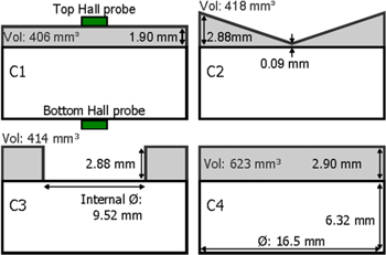
Figure 16. Cross-sections and dimensions of the hybrid ferromagnetic (shaded)–superconductor (white) configurations (F/S hybrids) investigated experimentally and numerically in [97]. Reprinted from [97], copyright 2014, with permission from Elsevier.
Download figure:
Standard image High-resolution imageNumerical modelling using the Brandt method [174, 175] was used initially to determine the current distribution as a function of applied field based on equation (4) and Campbell's equation [63, 82] was then used to understand and compare the dynamics of the flux penetration for the hybrid structures. The soft ferromagnetic property of the FeNi alloy was incorporated by modifying the left hand side of Campbell's equation from  to
to  where μr is represented by the function:

where μr,max = 1.7 × 10³ and μ0Msat = 1.4 T based on experimental measurements of the material's B–H curve. Similarly, a more precise fitting function can be used to represent the field dependence of the ferromagnetic material, μr(H), as described for the H-formulation section 3.2.1 and in [73, 74, 76, 202]. The numerical modelling in [97] provides a valuable insight into the difference in the contour lines of A when the ferromagnet is added to the bulk, as shown in figure 17, and how this affects its magnetization. The ferromagnet acts as a shield by concentrating and deflecting the magnetic flux lines from the TFM, but the overall trapped flux is enhanced in such structures.
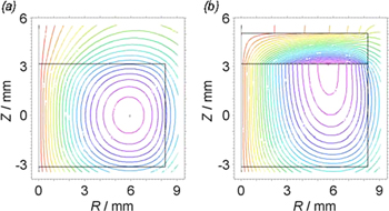
Figure 17. (a) Contour lines of the vector potential A in the fully magnetized remanent state for the superconductor without any ferromagnetic alloy addition in [97]. The results are obtained by solving Campbell's equation [63, 82]. (b) The same contour lines for the hybrid ferromagnet–superconductor structure C1 shown in figure 16. Reprinted from [97], copyright 2014, with permission from Elsevier.
Download figure:
Standard image High-resolution image5.3. Hollow bulk cylinders and tubes for shielding
In addition to acting as TFMs with high magnetic fields, hollow, cylindrical or tube-shaped bulk superconductors are also able to shield magnetic fields in a more efficient way than an equivalent ferromagnetic cylinder [203–205]. This shielding property has also been exploited in bulk superconductor reluctance machines [206, 207], where the magnetic field along the direct axis is enhanced by reinforcing the low reluctance path provided by the ferromagnetic material in the rotor.
In [204], the authors present an analysis of the magnetic shielding properties of a polycrystalline Bi-2223 superconducting tube subject to ac and dc axial magnetic fields. A numerical model based on [174, 175] is again used to simulate the experimental results. The tube can effectively shield an axial field up to a threshold axial field, Blim, that is determined by the length of the tube and its mean radius, but also the exact Jc(B) dependence of the superconductor. For decreasing tube length, Blim can be severely reduced due to demagnetization effects. Two mechanisms for the field penetration in the superconductor are described: one from the external surface and one from the opening ends of the tube; the latter being supressed for long tubes. Finally, the shielding factor is increased for increasing frequency, which is explained in terms of the power law, shown in equation (7). However, the effect of heat generation due to the motion of vortices was not examined, which may have a significant influence as described in [116].
In [205], this study is extended to analyse the effect of a cap on the ends of the tube, effectively closing the tube, and for tubes of shorter length, this has a noticeable, positive effect on the maximum shieldable field and the uniformity of the shielding. In addition, the effect of a non-superconducting joint and of inhomogeneities in the superconducting properties is investigated, which can both act to reduce the magnitude and location of maximum field attenuation.
Finally, in [208], the authors investigate the shielding properties of hybrid ferromagnetic-superconductor shielding tubes, which had previously been studied mostly experimentally [209–211]. The addition of a ferromagnetic cylinder either inside or outside the superconducting cylinder, as shown in figure 18, can substantially improve the shielding limit, which is maximized using the Ferro Out configuration, i.e., the ferromagnetic tube is placed outside the HTS tube. With the assistance of numerical simulations, which include the electrical properties of the superconductor and saturation of the ferromagnet, the shielding effect for the ferro out configuration is decomposed into two processes: attenuation from the ferromagnetic layer (independent of the HTS layer) and a decrease in magnetic flux density in the wall of the HTS tube, according to its own shielding factor. The mechanism for the Ferro In configuration is slightly different in that the presence of the ferromagnetic tube improves the magnetic field decay in the HTS tube. The height of the ferromagnetic tube also plays an important role, which can be optimized using numerical methods.

Figure 18. (a) Configurations of the ferromagnet–superconductor tubes considered in [208]. The ferromagnetic tube (black) is placed either (2) inside (Ferro In) or (3) outside (Ferro Out) the HTS tube. (b) The shielding factor (SF) as a function of applied magnetic flux density for the three configurations. © 2010 IEEE. Reprinted, with permission, from [208].
Download figure:
Standard image High-resolution image
6. Conclusion and view towards the future
In summary, this paper provides a comprehensive review of the current state of the art in modelling the magnetization of bulk superconductors, including both (RE)BCO and MgB2 materials. Numerical modelling is a powerful tool to understand the physical mechanisms of their magnetization, to assist in interpretation of experimental results, and to predict the performance of practical bulk superconductor-based devices. It is also a particularly important and cost-effective method to guide both superconducting material processing and practical device design as many superconducting applications head towards the commercialization stage of their development in the coming years.
A simple analytical method to calculate the trapped field of a bulk superconductor based on the Bean critical state model is described, in addition to an overview of the analytical and numerical techniques used to model superconducting materials in general. The commonly used practical techniques to magnetize bulk superconductors are summarized with a particular focus on PFM, which is promising as a compact, mobile and relatively inexpensive magnetizing technique. A number of numerical models developed to analyse the issues related to PFM and optimize the technique are described in detail, including understanding the dynamics of the magnetic flux penetration and the influence of material inhomogeneities, thermal properties, pulse duration, magnitude and shape, and the shape of the magnetization coil(s). The effect of externally applied magnetic fields in different configurations on the attenuation of the trapped field is also discussed. A number of novel and hybrid bulk superconductor structures are described, including improved thermal conductivity structures and ferromagnet–superconductor structures, which have been designed to overcome some of the issues related to bulk superconductors and their magnetization and enhance the intrinsic properties of bulk superconductors acting as TFMs. Finally, the use of hollow bulk cylinders/tubes for shielding is analysed.
With a view towards the future, many of the numerical techniques developed so far provided detailed qualitative results based on valid assumptions, but more quantitative results can be made with more accurate assumptions, including the input data used for the models—for example, improving the Jc(B, T) characterization of (RE)BCO bulk superconductors using a number of sub-specimens from the sample. This task, however, is more challenging than merely taking more specimens from a sample because often the estimated macro-Jc of the whole sample is smaller than the micro-Jc measured for small samples. As with all numerical modelling, trade-offs need to be made based on valid assumptions, where possible using data that have been verified experimentally.
The complexity of numerical models continues to increase, allowing researchers to simulate increasingly complex geometries and situations with various realistic parameters and conditions. Again there are trade-offs for the numerical technique itself, including, for example, the number and type of mesh elements, error tolerances and the use of symmetry, and analytical models are a helpful tool to check the sensibility of the numerical model in its basic form. The use of symmetry in the case of a cylindrical, disc-shaped bulk greatly alleviates the computational requirements, but there are several cases where a 3D model is needed. A 2D axisymmetric model may take up to an hour or two, but 3D models of even a single 3D bulk can require hundreds of thousands of elements to ensure sufficient accuracy and can take the good part of a day or longer to solve for one particular set of parameters. For models to extend to more complex shapes and arrays in 3D, which is required for superconducting device modelling, as well as for modelling stacked tape pseudo-bulks, there is a strong need for improving the computational speed and memory requirements by the refinement of existing techniques and the development of new ones.
Acknowledgments
Dr Mark Ainslie would like to acknowledge the support of a Royal Academy of Engineering Research Fellowship. Professor Hiroyuki Fujishiro would also like to acknowledge support in part by a Grant-in-Aid for Scientific Research from the Ministry of Education, Culture, Sports, Science and Technology, Japan. This research was also supported in part by a Royal Society International Exchanges Scheme grant, IE131084.