
Abstract
The atom-scale characterisation of interfaces between transition metal oxides and liquid water is fundamental to our mechanistic understanding of diverse phenomena ranging from crystal growth to biogeochemical transformations to solar fuel production. Here we report on the results of large-scale hybrid density functional theory-based molecular dynamics simulations for the hematite(001)-liquid water interface. A specific focus is placed on understanding how different terminations of the same surface influence surface solvation. We find that the two dominant terminations for the hematite(001) surface exhibit strong differences both in terms of the active species formed on the surface and the strength of surface solvation. According to present simulations, we find that charged oxyanions (-O−) and doubly protonated oxygens (-OH ) can be formed on the iron terminated layer via autoionization of neutral -OH groups. No such charged species are found for the oxygen terminated surface. In addition, the missing iron sublayer in the iron terminated surface strongly influences the solvation structure, which becomes less well ordered in the vicinity of the interface. These pronounced differences are likely to affect the reactivity of the two surface terminations, and in particular the energetics of excess charge carriers at the surface.
Export citation and abstract BibTeX RIS

Original content from this work may be used under the terms of the Creative Commons Attribution 3.0 licence. Any further distribution of this work must maintain attribution to the author(s) and the title of the work, journal citation and DOI.
1. Introduction
Interfaces between transition metal oxides and liquid water have attracted considerable attention in the research community due to their importance in e.g. atmospheric science [1], catalysis [2], energy storage [3], colloid chemistry [4], energy harvesting [5, 6], and artificial photosynthesis. Whilst much effort is currently invested to improve the properties of oxide materials for a range of different applications, by e.g. nanostructuring [7] and doping [8], it becomes increasingly important to obtain also a better molecular understanding of their interactions with liquids and electrolytes.
There are a number of experimental techniques available to elucidate the structural and electronic properties of oxides in contact with liquid water. For instance, crystal trunctation rod (CTR) experiments can give information on stable surface terminations as well as changes in the layer structure upon solvation [9, 10]. Sum frequency infrared spectroscopy is a powerful tool to probe vibrational modes at the surface of specific crystal faces [11, 12]. And with regard to electronic properties, transient absorption spectroscopy (TAS) emerged as a powerful technique to determine the lifetime of excess charge carriers in transition metal oxide photoelectrodes [13]. The molecular-scale interpretation of these measurements can be challenging, however. Here atomistic molecular dynamics simulation of aqueous interfaces can give valuable atomistic information that either complements available experimental data or helps with their interpretation.
Classical molecular dynamics simulations have been employed for modelling of oxide/water systems for some time and they gave insightful information mostly on structural properties [14]. However, the oxide/water interface is a chemically active region, where electronic polarization effects can be strong and where proton attachment and dissociation events occur frequently. The energetics of surface protonation, let alone chemical reactions of adsorbates, are difficult to describe correctly with classical force field approaches. It is therefore desirable to develop more accurate approaches like density functional theory (DFT)-based molecular dynamics simulation (MD) that, at the same time, can be used to sample the important solvent configurations, and indeed thermal fluctuations, at the interface.
In a series of recent papers, Sprik and co-workers developed and applied the DFTMD approach to investigate the energy level alignment [15], electric double layer [16] and the thermochemistry of proton coupled redox reactions at the TiO2/water interface [17]. Our group has recently carried out similar DFTMD simulations of another important interface, hematite (α-Fe2O3)- liquid water [18]. One of the most abundant metal oxide minerals on Earth, hematite has regained much attention in recent years for its prospect of efficiently converting sunlight into chemical energy via photoelectrochemical (PEC) water splitting [5, 6].
Of the different crystal faces of hematite, the (001) surface is considered to be the most prevalent one. It has therefore been extensively studied both by experiment [10, 19–21] and theory [22, 23]. Moreover, there are two major terminations for this surface that have been shown to be of particular interest [19, 24, 25]: oxygen and iron termination. Other terminations are stable e.g. under presence of surface vacancies [26]. In our previous investigation, that focused exclusively on the oxygen terminated (001) surface in contact with liquid water, we found that the surface protons form distinct binary patterns with protons pointing either in-plane or out-of-plane. The patterns exist for about 1 ps and spontaneously interconvert in an ultrafast, solvent driven process within 50 fs. This results in only about half of the terminating protons pointing towards the solvent and being acidic, and half of the protons pointing in-plane.
In this work we investigate the second most dominant termination of the hematite (001) surface, denoted iron termination, in contact with liquid water, see figure 1(a). As in our previous investigation on the oxygen terminated surface, we use DFTMD employing the hybrid density functional HSE06 with the fraction of exact exchange reduced to 12%. This functional was shown to reproduce the antiferrosymmetric spin pattern and other electronic properties such as band gaps and band ordering very well [18, 27]. The hematite slab is solvated with about 35 Å of water and the picosecond interfacial dynamics probed with DFTMD. We then characterise the influence of solvation on the hematite layering, the structure and dynamics of the terminating hydroxyl groups as well as the solvent structure close to the interface.
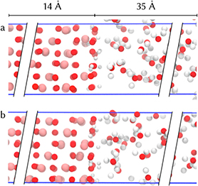
Figure 1. Hematite/liquid water simulation cells showing only the interface part: iron termination (a) and oxygen termination from [18] (b). The fully periodic box is shown with blue bars. For each of the slabs (hematite and water), the dimension along the surface normal is indicated.
Download figure:
Standard image High-resolution imageWe find that the surface protons of the iron terminated surface have a much stronger preference to point in-plane, or even away from the solvent than in case of the oxygen terminated surface. This is due to one iron sublayer missing in the iron terminated surface. As a consequence of this, solvation of the iron terminated surface is less strong and the water network is less structured than for the oxygen terminated layer. Importantly, we observe spontaneous proton dissociation and attachment events within the surface that were not observed before for the oxygen termination. Our simulations suggest that in addition to neutral (-OH) terminations, oxy-anions (-O−) and doubly protonated terminal oxygen atoms (-OH ) co-exist on the iron surface at the point of zero potential charge.
2. Computational details
The simulation of the iron terminated hematite/water interface is carried out similarly as reported previously for the oxygen terminated system [18]. We modelled a fully periodic slab system with a hematite layer of about 14 Å, and a water layer of about 35 Å, (see figure 1). The hematite slab consists of a  bulk structure super cell with 30 atoms each excluding terminations, while the water layer has 92 water molecules. Previous simulations have shown that this system size is sufficiently large to ensure bulk-like properties in the middle of the slabs [18] which is supported by experiment [28].
The hematite layer was initially set up to have bulk unit cell geometry followed by adding the surface oxygen layer necessary to make the slab symmetric [9] and protonating the surface according to the point of zero charge [29]. This way, for both terminations there was no net dipole for the slabs along the surface normal [30]. This part of the system has been constrained for the classical pre-equilibration of the water layer. Since full equilibration is not computationally feasible at DFT level, the system was pre-equilibrated with classical force fields [31, 32] at 330 K and 1 atm first, followed by DFT-MD equilibration of the whole unconstrained system. From the classical MD trajectory, two snapshots at 100 ns apart have been selected as starting points for two independent DFT-MD runs. Therefore, the solvent configurations in the two snapshots are uncorrelated. The results reported here are averaged over 15 ps (oxygen termination, see [18]) and 7.5 ps (iron termination) of surface solvation dynamics.
We estimated finite size effects due to the short, lateral dimensions by performing an additional calculation on a  super cell system with the same water layer thickness as before and the same simulation methodology. To make these additional calculations computationally feasible, we removed two middle iron layers in the initial
  hematite bulk structure. After this step and classical pre-equilibration as outlined above, 7 ps of surface dynamics have been sampled.
In order to understand how our results for the iron-terminated surface depends on the choice of density functional, we compared the present hybrid functional calculations to molecular dynamics at the PBE+U level. Starting from eight equidistant configurations from the HSE06(12%) trajectory for the  system, we branched off simulations at DFT+U level with an effective
  [27, 33, 34] resulting in a total of 9.5 ps of surface dynamics.
As shown in previous work [18, 27] hybrid functionals are necessary to describe both electronic and structural properties accurately. With other approaches like DFT+U it is difficult to describe more than one important property well at the same time, such as the magnetic moment on the iron atoms and the internal geometry [27, 33, 35, 36]. We have used the HSE06 functional [37] with 12% Hartree–Fock exchange (HFX) [27], auxiliary density matrix method (ADMM) [38], Goedecker–Teter–Hutter (GTH) pseudopotentials [39] and D3 dispersion correction [40] with Becke–Johnson damping [37]. Only the 3s, 3p, 3d and 4s electrons (for iron atoms) and the 2s and 2p electrons (for oxygen atoms) were treated explicitly. We have performed a NPT simulation with a flexible and fully periodic simulation box at 330 K and 1 atm using the Quickstep module from CP2K [41] with a time step of 0.5 fs.
3. Results
3.1. Solid interface structure
For the interpretation of crystal truncation rod (CTR) experiments, it is helpful to have information on an atomistic level, since the fit of the model to the experimental data involves a large number of degrees of freedom [6, 9, 10, 42]. Figure 2 shows the layer positions relative to the experimental bulk structure. For each layer and each frame of the simulation, a single plane has been fitted using singular value decomposition. The central oxygen layer of the symmetrically layered hematite slab has been used as point of reference for measuring distances between the layers. The resulting ensemble averaged layer positions suggest that the oxygen-terminated hematite structure resembles closely the bulk structure, as shown experimentally [9, 43]. The slab thickness is slightly higher for the oxygen termination, leading to hematite density being reduced by 1%. For the iron termination, the slab thickness is reduced, compared to the bulk structure with the same number of oxygen layers. This result is expected as an iron sublayer is missing beneath each of the two slab surfaces when compared to the bulk structure. The relative reduction in thickness between the two terminations of about 0.3 Å, is in good agreement with experiment [9].
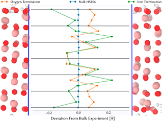
Figure 2. Layer positions along the surface normal averaged over the trajectory for both trajectories. The experimental bulk structure [44] is used as reference. Data for oxygen terminated hematite are taken from [18].
Download figure:
Standard image High-resolution image3.2. Liquid interface structure
The structural properties of the liquid phase of the interface are of particular importance for the understanding of charge transfer mechanisms. To compare the two most common terminations [9, 14, 19], the topmost bulk-like layer that is shared between both of these terminations has been chosen as the point of reference, namely the second oxygen layer. This layer has been fitted by a plane using singular value decomposition. For any atom, the distance to said plane has been determined and collected in a histogram over the full trajectories.
Figure 3 shows the atom number density for the two terminations. For the iron termination, the single iron layer is not divided into two sublayers as it would be the case for the oxygen termination, but the variance in positions is similar for both terminations which hints towards similar rigidity of the iron layers. However, the variance in position of oxygen atoms at the surface is much higher in the case of the iron termination, since there are less subsurface iron atoms stabilising this layer. This has a direct influence on the hydrogen positions which have been analysed in-depth before [18] for the oxygen termination. The first peak is due to hydrogen atoms in the same plane as the surface oxygen atoms, and the second peak is due to hydrogen atoms pointing towards water. The in-plane peak is much broader for the iron termination, simply because there are fewer iron atoms in the subsurface layer. This opens up more volume and reduces the Coulomb repulsion between the protons and Fe3+ sites. Besides, the aforementioned variance in oxygen atom positions contributes to a broadening of both hydrogen peaks in the histogram. It is worth noting that the ratio of the integral values of the in-plane and out-of-plane peak are different for the two terminations. While for the iron termination the ratio is  , for the oxygen termination it is
  . This means that for the iron-terminated hematite fewer protons are oriented towards water than for the oxygen-terminated hematite. Consequently, fewer protons are favourably oriented for deprotonation. The reasons for this, in particular the hydrogen bond network across the surface, are discussed separately further below.
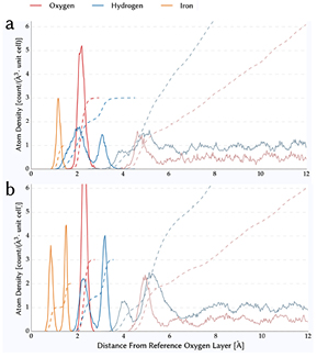
Figure 3. Atom number density for (a) iron terminated hematite/water interface simulated in present work and (b) oxygen terminated hematite/water interface taken from [18]. Solid lines show the binned histogram while dashed lines show the integral atom number density.
Download figure:
Standard image High-resolution imageFigure 4 shows the density profile of liquid water. Reaching the bulk water density within 5 Å, of the surface confirms the bulk-like structure in the middle of the water slab. Surprisingly, for both terminations, there is only one prominent peak of water density hinting towards a single layer of water molecules forming the adsorption layer with the oxygen termination exhibiting a smaller second peak. For other liquid water–solid interfaces, two large peaks have been found regularly: e.g. for gold [45], rutile TiO2 [16], silica SiO2 [46, 47], corundum Al2O3 [43]. This points towards strong screening of the hematite surface dipole by the adsorbed water layer as follows. In the atom number density plot in figure 3, it is clearly visible that the surface dipole of the iron termination is smaller than the one of the oxygen termination, since the number of contributing OH groups pointing towards the aqueous part of the interface is smaller. This results in a smaller surface dipole and a shorter screening length, explaining the absence of a second peak in the number density profile for the iron-termination. The single-peak density profile found in our simulation matches experimental x-ray reflectivity (XR) results [43] and is important for interpretation of experiments probing the work function of hematite [48].

Figure 4. Water density profile for the two terminations averaged over the full trajectories.
Download figure:
Standard image High-resolution imageThe width of the first density peaks is an indicator for the strength of the adsorption. A narrow peak would be the result of strongly confining interactions. While this measure is similar for both terminations within the accuracy of this simulation, the position of this peak is significantly shifted by 0.2 Å, along the surface normal vector between the two terminations. Since the missing iron sublayer in the iron termination results in a reduced distance between the two outermost oxygen layers, this shift is expected (see figure 2). This shift is in perfect agreement with experimental crystal truncation rod (CTR) results from Trainor et al who found 0.2 Å shift, as well [9].
Integrating the density from figure 4 over the first peak results in a surface coverage that is about 25% lower for the iron termination than for the oxygen termination. This may be a direct consequence of the smaller surface dipole resulting in increased disorder [48], less efficient packing and therefore lower coverage. However, this greatly reduces the number of hydrogen bonds with a water molecule as donor and a hematite oxygen atom as acceptor, as described below.
3.3. Autoionization
Within 450 fs of ab initio MD simulation of the aqueous interface we observe spontaneous proton transfer between two hydroxyl terminating groups. This results in the formation of a formerly negatively charged oxyanion (O-) and a doubly protonated oxygen atom (OH ), which remain stable until the end of the simulation. One such proton transfer event is observed for each of the 4 surfaces in our two simulation runs, and two such events on one surface.
The proton transfer can occur via two different path ways: direct transfer between two neighbouring oxygens and water molecule-mediated. For the solvent-mediated process, there are six stages (see figure 5). First, a water molecules reorients such that it accepts a hydrogen bond from a OH group ((a) in figure 5) at the surface followed by this water molecule donating one hydrogen bond to a neighbouring surface OH group (b). Since this now forms a cooperative chain of hydrogen bonds, these bonds are stabilised [49, 50] helping the migration of a proton from a surface OH group to the water molecule consequently forming an hydronium ion (d). Although hydronium hydrogen bonds are stronger than regular water hydrogen bonds [51], the one to the surface oxygen that just lost a proton breaks quickly (e), leaving the hydronium ion stable for about 50 fs which is typical for the lifetime of a hydronium ion in water [52, 53] and matches similar reports for TiO2 surface [54, 55]. In the final step, the proton partaking in the in-plane hydrogen bond along the surface is pushed towards the former acceptor site and forms a bond there while still being connected to the former donor site by forming a hydrogen bond in reverse direction (f). This last step is also observed spontaneously multiple times without the mediation of a hydronium ion, but in all cases, a transient cooperative hydrogen bond network is formed as precursor of the deprotonation. Over the course of the trajectory, the total number of surface protons remains stable, so there is no net deprotonation of the hematite surface.
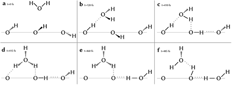
Figure 5. Steps of the solvent-mediated proton transfer process (a)–(f). The hematite slab surface is indicated by a thin grey line; above that is the water slab.
Download figure:
Standard image High-resolution imageDuring stages (d) and (e) in figure 5, we observe an additional water on above the hydronium ion accepting a hydrogen bond from the third hydronium proton that is not taking part in the hopping mechanism at the surface. This geometry is close to the one of the Eigen cation which has shown to support proton hopping [56].
This process describes a proton hopping mechanism for forming an energetically favourable surface termination similar to the Grotthuss mechanism and hints towards hydronium supporting formation and cleavage of surface hydroxyl groups [57]. This is compatible with previous findings that found proton mobility to correlate with the rate of hydrogen bond cleavage [58], since we have found particularly short life times for hydrogen bonds across the surface (see table 1).
Table 1. Lifetimes of HB between and within the subsystems water and hematite relative to the lifetime of HB within bulk water for the two terminations.
| Donor | Acceptor | Rel. lifetime (%) iron | Rel. lifetime (%) oxygen | ||
|---|---|---|---|---|---|
| Stillinger | Average | Stillinger | Average | ||
| Water | Water | 100 | 100 | 100 | 100 |
| Water | Hematite | 31 | 34 | 83 | 82 |
| Hematite | Water | 116 | 89 | 114 | 75 |
| Hematite | Hematite | 20 | 31 | 19 | 48 |
Note: Shown for the method proposed by Stillinger [59] and for averaging the distribution of lifetimes employed in [18].
We attribute the lack of observations of this mechanism for the oxygen surface to the subsurface iron atoms that stay very close to the surface and inhibit not only cooperative hydrogen bonds [18] which would drastically reduce the frequency of proton hops [60] but also the transition of protons between neighbouring surface oxygen sites. Although this complex solvent-mediated process is observed only once in our simulation, it happened fast and spontaneously which points towards this process occurring frequently for larger systems, in particular since autoionisation in general is underestimated by neglecting quantum nuclear effects [61].
The direct transfer has been observed for quartz [62]. This gives an atomistic description of the process forming the experimentally [20, 24] found Fe=O sites that have been shown to be stable in vacuum [63] even though hydroxylated surfaces have been estimated to be more stable in aqueous conditions [25]. Other experiments support the formation of Fe=O sites for low water coverage [64] since this correlates with reduced hydroxyl group coverage [65], which explains why this behaviour is observed for the iron termination only since the oxygen terminated surface has a high water coverage (see figure 4).
3.4. Hydrogen bonds
Hydrogen bonds play a major role in surface termination orientation [66], solvent ordering [48, 67] and work function [68] for solid–liquid interfaces. Therefore, it is important to get a better understanding of the impact of the hematite surface on the stability and orientation of the hydrogen bonds in water and at the surface. We consider hydrogen bond formation if the O-O distance is less or equal to 3.5 Å, and the O-H-O angle is at least 160. Experimental evidence is pointing towards temporary violations of these criteria on the timescale of a few 10 fs [69], which was sometimes attributed to libration movements [70, 71]. Besides, the fixed distance and angle criteria have been criticised for its somewhat arbitrary cutoff parameters [72, 73]. For these reasons, we allowed transient violations of the hydrogen bond criterion up to a time τ. This time interval has been parametrised to reproduce the HB lifetime distribution from bulk water [69] for the bulk-like section of the water layer in the system.
Given the comparably short trajectory it is hard to find a reliable criterion to measure the lifetime of hydrogen bonds [49, 59]. In table 1, we compare two approaches: calculating the average duration of an uninterrupted hydrogen bond between unique triples of donor, proton and acceptor [18] and extracting the lifetime from the fitted exponential decay constant of the time-shifted population of uninterrupted hydrogen bonds [59]. While the difference in the actual numbers illustrates the precision to be expected from these methods at the time scale of our trajectories, the overall picture is the same: hydrogen bonds from water to hematite have a substantially shorter lifetime for the iron termination than for the oxygen termination.
There are four types of hydrogen bonds that have been investigated; hydrogen bond donor and acceptor are water molecules in bulk solution, protonated surface oxygen as hydrogen bond donor (acceptor) and a solvent water molecule as hydrogen bond acceptor (donor), and two oxygen atoms in the top oxygen layer as hydrogen bond donor and acceptor, respectively. Table 1 shows the calculated lifetimes as a percentage of the lifetime of hydrogen bonds in bulk water, for all four types of hydrogen bond donor-acceptor interactions and for both surface terminations (O and Fe termination). The resulting lifetimes for the two terminations are very close to each other with the exception of the water (donor)-hematite (acceptor) hydrogen bonds, where the lifetime is much shorter for the iron termination. We attribute this difference to the stronger preference for the iron-terminated surface to orient the proton parallel to the surface (see figure 3) and to its lower surface coverage (see figure 4). The preferential OH alignment parallel to the surface (see figure 7) possibly leads to a flattening of the potential energy surface for adsorbed water molecules. Consequently, the ability to switch HB acceptor increases leading to shorter lifetimes. Lower coverage of the surface is generally expected to increase disorder [48] resulting in more metastable adsorbate configurations, as long as the water–water hydrogen bond interaction is not much stronger than the substrate-water one [74] which in fact is the case for hematite, as shown in table 1.
Figure 6 illustrates the disruption of the hydrogen bond network at the interface. The bars show the fraction of water molecules in the first solvation layer of the interface that donate zero, one or two hydrogen bonds to neighbouring water molecules minus the corresponding fraction for water molecules in the bulk. The oxygen terminated surface is shown in red, the iron terminated in green, and for comparison we also show data for the Au/water interface, taken from the literature [45]. Near the surface, the number of water molecules with no or one hydrogen bond is significantly higher than in bulk, while the number of water molecules with two hydrogen bonds is greatly reduced. This means that the regular hydrogen bond pattern is greatly reduced, thus facilitating [75, 76] the occurrence of hydronium at the interface, as observed in our calculations and other simulations [77]. Comparing the extent of the disruption of the hydrogen bond network for the gold/water interface [45] to hematite shows that hematite exhibits the same behaviour while having a much smaller impact on the water structure close to the surface than gold (see figure 3). Since previous studies suggest that the orientation of water molecules close to the surface cannot be attributed to the different van der Waals potential of the hematite surface alone [78], the actual surface termination and OH group orientation seems to have little effect on the hydrogen bond structure within the first adsorbed water layer.

Figure 6. Number of HB donations per water molecule at the interface minus the number in bulk water. The bars show the fraction of water molecules in the first solvation layer of the interface that donate zero, one or two hydrogen bonds to neighbouring water molecules minus the corresponding fraction for water molecules in the bulk. The oxygen terminated surface is shown in red, the iron terminated in green, and for comparison we also show data for the Au/water interface, taken from the literature [45].
Download figure:
Standard image High-resolution image3.5. Surface OH group patterns
The orientation of surface OH groups and the patterns they form influence solvent interaction processes like water splitting or crystal growth [22, 79]. Figure 7 shows the most stable patterns for both the iron and the oxygen termination. A pattern is defined by a unique combination of OH orientation (in-plane or out of plane) and number of protons per oxygen site.
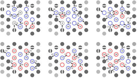
Figure 7. The three most stable surface patterns including their hydrogen bond probabilities for the iron termination (top row) and the oxygen termination [18] (bottom row). Circles denote surface oxygen sites, the number of coloured rings around one site gives the number of protons bonded to this site. Red and blue sites have their protons perpendicular to the surface and parallel to the surface, respectively. Black circles denote bare oxygen sites. Arrows give the direction of hydrogen bonds from donor to acceptor. Numbers on arrows give the probability of forming this hydrogen bond in percent. Numbers on sites give their probability of donate (red circles) or accept (blue and black circles) a hydrogen bond to or from water. Filled circles illustrate periodic images of the simulation cell.
Download figure:
Standard image High-resolution imageIn direct comparison, it is striking that there are much more OH groups oriented along the surface for the iron termination than for the oxygen termination. This goes well with the atom number density in figure 3 and points towards hydrogen bonds stabilising the surface patterns. In general, iron termination oxygens are much less likely to accept a hydrogen bond from water which can be linked to the lower water coverage of the surface as shown in figure 4. It is interesting to see that there are multiple sites that do not accept hydrogen bonds on the 1 ps time scale, which is only rarely observed for the oxygen termination [18]. The greater distance between the top oxygen layer and the iron layer beneath (see figure 3) enables cooperative hydrogen bonds across the surface which supports autoprotonation events (see figure 5).
Even though the solvent-mediated proton hopping process creates an oxygen site with two protons that is separated from the site stripped of protons by one more oxygen, in the stable patterns, these two sites are always neighbours which minimises charge separation. The stability of this split termination is illustrated by the fact that all stable surface patterns found in the simulation have at least one such combination of a two-proton site and a bare site.
3.6. Finite size effects and dependence on density functional
We have investigated the effect of finite lateral system size on the atom number density by comparing the  calculations to results on the
  system. The
  system is a solvated
  hematite slab with the two middle iron layers removed to reduce the system size while leaving the antiferromagnetic ordering intact. The results are summarized in figure 8. It is interesting to see that peak positions and widths for all oxygen atoms are virtually identical (see panel (B), (D), (E) in figure 8). With a surface area more than twice as large for the
  setup, the sampling of surface configurations was significantly improved compared to the
  setup. Therefore, the spatial distributions are converged as far as the oxygen atoms are concerned. The only notable difference between the two setups are the terminating hydrogen atoms and the outermost iron sublayer (panel (A) and (C)). While the peak positions and integral values are still the same for the larger setup, their variance is somewhat larger. We expect this to be a consequence of the thinner hematite slab in the
  setup rather than a true finite size effect. The atoms of the outermost iron sublayer are more flexible than in the
  system, which affects the distribution of close-by terminating hydrogen atoms. Overall, the increase in surface area by more than factor of 2 in the
  system does not lead to significant changes, which validates our results reported here for the
  system.

Figure 8. Finite size effects for each peak (panels A–E) in the atom number density profile (figure 3). Shown are two curves each, one for the  super cell (thin green) of hematite as used throughout this work and one for the
  super cell (thick blue) with more than double the surface area. Distances with respect to a plane fitted through the first sub-surface oxygen layer of bulk hematite. Peaks are normalised to their maximum value.
Download figure:
Standard image High-resolution image
As most previous calculation on hematite have been carried out at the PBE+U level of theory, we have also performed MD simulations with this functional. In seven out of eight calculations, we observe deprotonation of two neighbouring oxygen atoms followed by spontaneous dissociation of these O atoms from the hematite surface and formation of solvated O2. This exposes the iron atom layer to water. Although this relaxation path was unexpected, we note that iron termination is energetically preferred for a clean surface without adsorbed water at PBE+U and GGA level [23, 36]. For the interface with water, several experimental studies consistently report the oxygen layers of the hematite structure to be exposed to the solvent [6, 9, 21]. Hence, we conclude that PBE+U does not reproduce the experimental surface termination, at least with the standard choice for the U parameter, and that a hybrid functional gives results in better agreement with experiment.
4. Conclusions
The present work illustrates the strong influence that the surface termination can have on the water structure near the surface, and in particular on the surface coverage. The hematite/water system is a point in case. The missing iron sublayer in the iron terminated surface allows surface protons to point away from the solvent, even towards the iron layer. With both iron sublayers intact, this is not possible for the oxygen terminated surface simply due to geometric reasons. As a consequence of this, the density of protons pointing towards the solvent is significantly higher for the oxygen than for the iron terminated surface. According to our simulations, this leads to a stronger solvation of the surface. The differences in solvation could also influence the chemical reactivity of the two surface terminations, and in particular the stability and nature of excess charge carriers (holes, electrons) at the interface.
We have also observed a solvent-mediated proton transfer locally altering the surface oxygen protonation and we elucidated its interplay with the hydrogen bond network. It is interesting to note that instead of dissociation of a proton and formation of a bulk solvated hydronium, the proton prefers to stay on the surface, which leads to formation of oxy-anions (-O−) and doubly protonated terminal oxygen atoms (-OH ). Formation of a hydronium ion is observed only temporarily for about 50 fs. Finally, we have identified surface OH group orientation patterns that are stable on the 1 ps time scale and we have analysed differences between the two hematite terminations.
The structures reported in this work could be used to improve classical force fields to allow for realistic simulations of these interfaces over longer length and time scales. In addition, the simulations reported here and in previous work [18] provide a solid basis for investigation of the nature and energetics of excess hole and electron in hematite/water interfaces, relevant to water splitting photocatalysis [5], crystal growth [80] and biogeochemical transformations [81, 82]. The constrained density functional theory method that was previously applied to calculation of electron transfer parameters for hole tunneling in oxide materials [83–85] may be extended to such interface problems. Work along these lines is currently ongoing in our laboratory.
Acknowledgments
GvR gratefully acknowledges a PhD studentship co-sponsored by University College London and Pacific Northwest National Laboratory (PNNL) through its BES Geosciences program supported by the U.S. Department of Energy's Office of Science, Office of Basic Energy Sciences, Chemical Sciences, Geosciences and Biosciences Division. MD simulations were carried out on ARCHER, the UK national HPC facility (Edinburgh), to which access was granted via the ARCHER Leadership pilot call and the Materials Chemistry Consortium (EPSRC grant EP/L000202). Data analysis was carried out with computing resources provided through a Microsoft Azure Sponsorship and supported by software made available by Tableau Inc.