Abstract
In comparison to traditional planar optical devices, compound-eye structured optical elements can reduce the number of components and their volume when being applied to wide-field imaging and sensing systems. However, the fabrication process for microstructures on a curvilinear surface has many difficulties since traditional fabrication techniques are planar. In this paper, we present a cost-effective method to fabricate microlenses on a spherical surface. Microlenses, of which the fill factor was about 78%, were formed using the thermal reflow technique, followed by multiple replication processes to transfer the microlenses from the planar substrate onto a spherical surface. We produced a curved mold with concave microlenses, and it allowed this method to be replicable. A polydimethylsiloxane elastomer was employed as the material for both the microlenses and the mold. The radius of curvature of the spherical surface was approximately 6.1 mm. The variation of the microlenses was analyzed, demonstrating high uniformity. The imaging performance of the microlenses is also presented. The curved microlens arrays were combined with image sensors, and sub-images of objects at various distances are shown. The experimental results demonstrate a high potential for curved microlens arrays being applied to compact mobile camera lenses.
Export citation and abstract BibTeX RIS

Content from this work may be used under the terms of the Creative Commons Attribution-NonCommercial-ShareAlike 3.0 licence. Any further distribution of this work must maintain attribution to the author(s) and the title of the work, journal citation and DOI.
1. Introduction
A microlens array (MLA) is composed of numerous small lenses with matching diameters. In recent work, MLAs have played an important role in several areas such as wavefront sensors [1], backlight modules [2], light extraction of organic light emitting devices [3], and imaging systems [4]. Omnidirectionally arranged optical elements, which are inspired by the compound eyes of insects, have attracted a great deal of research interest due to the capability of wide-field-of-view (FOV) imaging [5] and high-sensitivity detection [6]. Traditional optical elements for wide FOV, such as a fish eye lens, suffer from bulky lenses and stringent alignment [7]. Therefore, it is desirable to fabricate omnidirectional arrayed optical components. However, using only a traditional fabrication technique, the construction of microstructures on curvilinear surfaces is challenging. In the past, researchers have proposed several methods to obtain non-planar MLAs. Jeong et al accomplished the spherical configuration of an MLA through polymer using an elastomer membrane with microlens patterns. The membrane had previously been deformed by negative air pressure [7]. Radtka et al applied a unique laser lithography system that fulfils the requirements to expose spherical substrates [8]. Qu et al constructed an artificial compound-eye structure through femtosecond-laser microfabrication and a thermal–mechanical bending process [9]. Although these methods demonstrated the ability to fabricate an MLA onto spherical surfaces, they also suffer from disadvantages, such as the high cost of the facility, the special equipment required and a long processing time. In addition, a 3D fabrication process is relatively complicated and the area of the MLA which is covered is limited to the tilted angle of the substrate [8].
Polydimethylsiloxane (PDMS) is the most widely used silicon-based organic polymer. PDMS is optically clear, inert, non-toxic and typically non-flammable. PDMS is commonly used in the replication process due to its good plasticity. Furthermore, since PDMS has high optical transmittance in the visible wavelength, it is also considered a suitable material for lenses [10]. In our experiment, we adopted PDMS (Dow Corning SYLGARD 184) as the material for both the molds and the microlenses. By using the same material, we can minimize the mismatch of the thermal expansion to increase the yield rate.
In this paper, a novel approach to fabricating curved MLAs with a multi-replication process is demonstrated. The lens profile was achieved through the thermal reflow technique. Multiple replication processes were used to transfer MLAs from planar substrates onto a spherical surface, including fabrication of a curved PDMS mold with concave microlenses. Scanning electron microscope (SEM) data as well as the optical performance of the fabricated curved MLA are analyzed and presented herein.
2. Fabrication process
The curved MLAs were made of polymer materials. The fabrication process began with the opaque photoresist MLA being transferred into the PDMS MLA, which was transparent and flexible. The planar MLA was deformed into a curved MLA. The fabrication process is described in detail below. The overall process flow is illustrated in figures 2 and 3 accordingly.
2.1. Photoresist microlens array
Thermal reflow of photoresist is a favorable technique among the possible methods for microlens fabrication. The method is simple, fast and inexpensive, and requires no chemical etching or a high-temperature process. Microlenses are produced through heating photoresist cylinders, as shown in figure 1. The focal length of a planar–convex lens can be calculated based on the lens-maker's formula [11]:

where RC is the radius of curvature and n is the refractive index of the lens. Ideally, with the assumption that gravitational effect is negligible, which generally holds in the case of small lenses (less than 1000 µm), the shape of the microlens is expected to be a spherical surface [12]. However, if the ratio of height and diameter is too low, the volume of photoresist will not be significant enough to form a spherical lens, resulting in a concave region in the middle of the resist lens. Although a thicker photoresist layer would solve this problem, a thick photoresist layer is difficult to coat uniformly and multiple coatings increase the complexity of the process. Therefore, we designed the diameter of our microlens to be 200 µm to demonstrate our process.
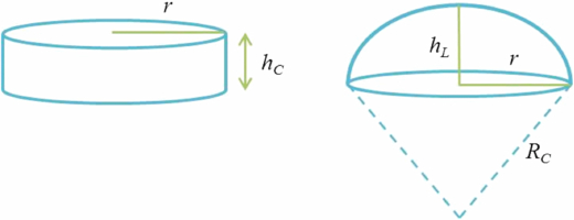
Figure 1. The geometry of photoresist using the thermal reflow process.
Download figure:
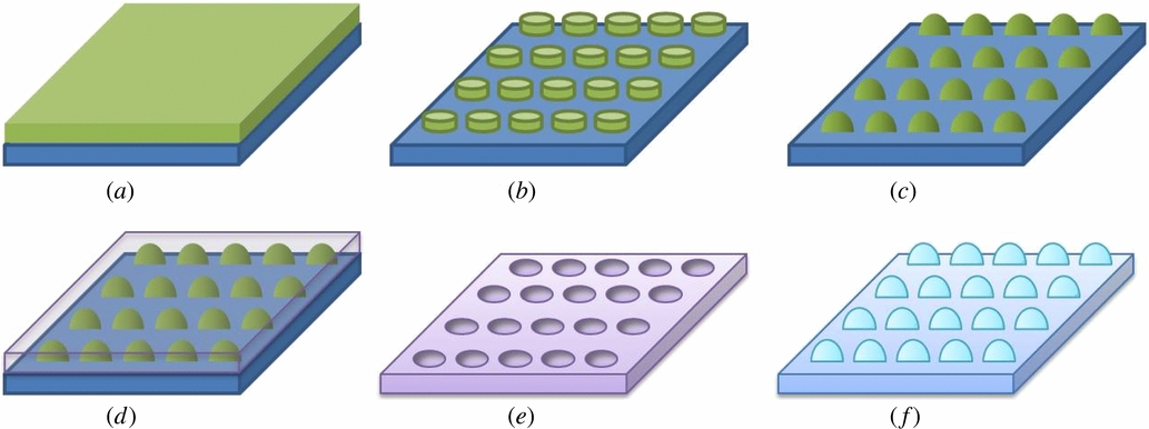
Standard image High-resolution imageIn the next step of the array fabrication of the photoresist microlens, the silicon substrate was cleaned using Piranha (H2SO4 + H2O2) and hydrofluoric acid sequentially. The sample was then dehydration-baked at 120 °C for approximately 10 min. The photoresist layer (AZ P4620) was spun at low speed to equally disperse the photoresist on the substrate and then at 800 rpm for 30 s, resulting in 25 µm thickness, as shown in figure 2(a). The resist cylinders were patterned by photolithography after a soft bake of 100 °C for 165 s, as shown in figure 2(b). We heated the photoresist cylinders at 160 °C for 10 min in order to obtain a spherical profile, achieving spherical photoresist microlenses through surface tension, as shown in figure 2(c).
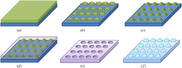
Figure 2. Fabrication process of the planar PDMS microlens array (MLA). (a) Spin-coated AZ P4620 photoresist on the silicon substrate. (b) The defined lens area by lithography. (c) Thermal reflow of photoresist cylinders into resist lenses. (d) The PDMS poured on the substrate and peeled off after curing. (e) Salinizing the concave PDMS mold. (f) Planar PDMS MLAs replicated from the concave mold.
Download figure:
Standard image High-resolution image2.2. Planar PDMS microlens array
In order to realize the curved MLA, the unbending photoresist microlenses should be transferred into planar microlenses with a flexible material, PDMS elastomer. To prepare the liquid PDMS, a mixture of PDMS base and curing agent in a 5:1 or 10:1 weight ratio was mixed. Since PDMS was used as both a master and servant mold, it is important to avoid damages during the stripping process. The different ratios of the two agents would result in distinct flexibility and curing time, thus making the stripping process easier, increasing the completeness of the polymer microlenses. The liquid PDMS was placed in a vacuum until the bubbles in the mixture were removed. The degassed mixture was then poured onto the silicon substrate with the photoresist MLA, serving as a molding template, as shown in figure 2(d). The PDMS-coated wafer was relaxed for 10 min in order to achieve a flat surface and then heated at 80 °C for 2 h. When curing was complete, the concave PDMS mold was stripped off, as shown in figure 2(e). The effect of thermal expansion during the curing step is minimized since we used the same material for both the master mold and the replica. However, adhesion between the mold and the replica was not negligible, and therefore surface treatment before the casting process was quite important in our experiment. To ensure an undamaged replicated pattern, the master mold was silanized using trichloro(1,1,2,2-perfluorooctyl)silane, which is commonly used as an anti-adhesion layer for nanoimprints. The silanizing agent forms a self-assembled monolayer on the surface of the master, which lowers the surface energy and prevents the PDMS contacting and bonding to the master's surface [13, 14]. A similar procedure was executed to form the planar PDMS MLA, which was easily released from the concave mold, as shown in figure 2(f).
2.3. Curved PDMS microlens array
After the planar PDMS MLA was fabricated, it was necessary to deform the planar PDMS MLA into a curved PDMS MLA. Unlike polymethylmethacrylate, PDMS has a high thermal stability, and therefore we are unable to deform the PDMS film directly through the application of heat [9]. Therefore, a master mold with a concave surface was necessary. A small container, which was previously cleaned by alcohol, was filled with liquid PDMS with a less flexible mixing ratio, and was capped with the silanized planar PDMS MLA, as shown in figure 3(a). A spherical interface was formed by pressing the flexible MLA with a spherical object continuously until the liquid PDMS was fully cured at room temperature, as shown in figure 3(b). The spherical object was 10 mm in diameter and the force of the pressure was 3.9 kg. A curved PDMS mold with concave MLA is hence fabricated. Figure 3(c) shows the curved mold which can be reused so that the curved MLA can be replicated simply and quickly. Finally, we poured liquid PDMS, which was mixed according to the specification, into the area of the spherical surface, relaxed for 10 min and cured at 80 °C for 2 h, as shown in figure 3(d). Following the peeling process, the PDMS MLA on the spherical surface was obtained, as shown in figure 3(e).
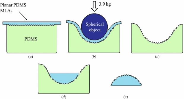
Figure 3. Fabrication process of the curved PDMS MLA. (a) Fitting covered planar MLAs onto a small container filled with liquid PDMS, (b) pressing the cap with a spherical object to form a spherical surface, (c) removing the planar MLAs and the object after curing and silanizing the curved PDMS moldwith concave MLA. (d) The liquid PDMS at the bottom of curved mold is then cured by heating. (e) The peeled off curved PDMS MLAs.
Download figure:
Standard image High-resolution image3. Experimental results and discussions
3.1. The PDMS microlens array on planar surface
In this section, we fabricated a photoresist MLA in a hexagonal pattern. The diameters of the MLAs were both 200 µm. An image of the reflowed hexagonal MLAs taken using a microscope (ECLIPSE 50i, Nikon) is shown in figure 4(a). The average height of square and hexagonal MLAs was approximately 20.8 and 20.7 µm, respectively. Figure 4(b) shows the SEM observation (JEOL, JSM-7600F) of the planar PDMS hexagonal MLA. We took pictures of the focused light spots with an optical microscope using an LED light source from below in order to examine the uniformity of the MLA, as shown in figure 4(c). The spot profiles were symmetric. This means each microlens is of good quality. In other words, the fabricated microlenses were symmetric. The distance between the light source and the MLA (approximately 12 cm) was much larger than the diameter of the microlens; hence, the rays of light could be considered parallel to the optical axis. The intensity distribution of each focused spot was analyzed using MATLAB®, as shown in figure 4(d), and the spot sizes were also measured. The uniformity of the MLA was analyzed by calculating the coefficient of variation


Figure 4. Hexagonal MLAs of 200 µm diameter and gap length 20 µm. (a) Microlenses under optical microscope. (b) The SEM picture of planar PDMS MLAs. (c) The image of light spots taken from an optical microscope with the LED light source below and (d) the intensity profile transferred from (c) using MATLAB®.
Download figure:
Standard image High-resolution imageThe variation of the two MLAs was small (less than 5%), indicating high uniformity.
The focal length of a planar–convex lens is the distance between the planar plane and the focal point. Therefore, for the purpose of obtaining the focal length of the microlens precisely, we first focused on the top surface of the PDMS, which is the bottom of the PDMS lens, and found the clear edge of the microlens. We then turned the fine adjustment knob to move down the stage slowly. Light through the lens converged before the focal plane and diverged after it. The stage was adjusted until the objective lens captured the smallest and brightest light spot, the focal point. We concluded the above experimental results as well as the calculated fill factor of each PDMS MLA in table 1.
Table 1. The experimental results of the PDMS MLAs on a planar surface.
| Lens shape | Averaged diameter (µm) | Focal length (mm) | Beam spot size (µm) | Variation (%) | Fill factor (%) | Yield rate (%) |
|---|---|---|---|---|---|---|
| Hexagonal lens | 194.66 | 0.44 | 8.0 | 4.73 | 78.3 | 99.5 |
| Square lens | 193.43 | 0.51 | 8.8 | 3.45 | 77.3 | 98.6 |
In our experiment, the surface treatment is an important step during the replication process since the quality of the lens surface will severely affect the optical performance of the MLAs. Figure 5 demonstrates the replicated lenses from the untreated PDMS mold and the silanized PDMS mold. The microlenses fabricated from the untreated mold are quite visibly damaged. The yield rate of this MLA was less than 20%, and most of the microlenses were not replicated completely, resulting in the reduction of sag heights. On the other hand, the PDMS master mold treated with silanization produced a successful replication.
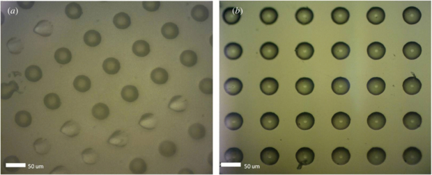
Figure 5. Planar PDMS MLAs replicated from different surface treated molds: (a) untreated PDMS mold and (b) silanized PDMS mold.
Download figure:
Standard image High-resolution image3.2. The PDMS microlens array on a curved surface
In this section, curved PDMS MLAs with hexagonal lenses were fabricated. The diameter and sag height of the dome (curved surface) are 10 mm and 2.6 mm, respectively. The radius of curvature of the spherical surface is approximately 6.1 mm. The perspective picture and the SEM images are shown in figure 6. The inset of figure 6(b) shows microlenses near the edge of the dome. During the pressing process, the microlenses were stretched, resulting in a wider gap. Because of the anisotropic force, gaps between the microlenses at the top were slightly larger than those near the edge of the dome. The detailed analysis will be described in the following subsection. We measured the 3D profile of the microlens at the top of the dome using white light interferometry (BMT, WLI Lab). The average surface roughness (Ra) over a 5 µm × 5 µm area on the microlens top surface was approximately 12–19 nm, indicating good optical smoothness for the refractive microlens, as shown in figure 7. We believe that the silanized surface improves the mold fabrication process significantly.

Figure 6. (a) Perspective image of curved PDMS MLAs. (b) SEM image of curved MLAs at the top of the dome. Inset: microlenses on the outer ring of the dome.
Download figure:
Standard image High-resolution image
Figure 7. (a) 3D profile of microlens scanned by white light interferometry. (b) Surface roughness of PDMS microlens over a 5 µm × 5 µm area.
Download figure:
Standard image High-resolution image3.3. Analysis of the deformation
Figure 8 shows the morphology of the hexagonal PDMS MLA measured by a probe-type surface profiler (KOSAKA, ET-4000A) before and after deformation of the PDMS molds. The uniformity of the planar MLA has been analyzed in the previous section, and we expected that the curved MLA would have the same uniformity providing there was no additional damage to the microlens during the replication process. However, being an elastomer, not only the planar surface but also the microlenses are deformed during the pressing step. The planar PDMS mold was deformed to a spherical surface, and the microlenses were pulled by surrounding stress. Therefore, the shape of the microlens will be changed. Furthermore, the spherical object was pressed downward, resulting in anisotropic force distributed on the spherical surface. Thus, the deformation of the microlenses in different regions would not be the same, and the uniformity of the curved MLA will differ from that of the planar MLA. However, this can be corrected by either a uniform pressing force [7] or pre-calibrated microlens dimensions.
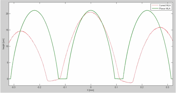
Figure 8. Surface profiles of hexagonal microlenses before and after deformation. The green line indicates planar microlenses while the red dotted line indicates the curved ones.
Download figure:
Standard image High-resolution imageIn the previous section, we calculated the uniformity of the planar MLA through the analysis of the intensity distribution of the focused spots. Nevertheless, when it came to curved MLAs, the LED light source of the optical microscope could not be projected at a normal incidence to every microlens since the stage of the microscope was not rotatable. Therefore, we analyzed the uniformity through another parameter. The profiles of the microlenses at the center and edge of the dome were measured and approximated to the sag equation without the high order term as [15]

where c is curvature at the vertex, as usual  , k is the conic constant, r is the radial coordinate measured perpendicular from the axis and z is a function of the distance from the lens center. The same curvature with different conic constant will have different surface types at the outer periphery. After curve fitting on the measured data, the conic constant k of the planar microlens was approximately 3.066, indicating that the surface profile before deformation was an oblate ellipsoid, not a perfect spherical surface. However, after pressing the planar surface into the spherical surface, k of the central and side lens reduced to −0.489 and 0.409, respectively, proving that the pressing process deformed not only the substrate but also the lenses. Furthermore, compared to planar microlenses, the profiles of the curved microlenses were closer to a sphere. In addition, we also analyzed the radius of curvature of each MLA. The averaged radii of curvature of the planar microlens and the curved microlens at the top and on the side of the dome were 257.7 µm, 346.8 µm and 276.0 µm, respectively. The lenses were pulled by surrounding stress, resulting in increased radii of curvature. The focal length was also increased after the pressing step. The deformation rate of the lens diameter was calculated. The diameter deformation of the central lens was 18.3%, which was larger than that of the side lens, 8.8%, demonstrating that the force was concentrated at the bottom of the spherical object. Since the planar PDMS MLAs were difficult to wholly deform into the hemispherical surface in our experiment, only the part near the bottom of the concave mold could satisfy the radius of curvature of the spherical object. Thus, we filled liquid PDMS only at the bottom of the concave mold. Therefore, although the pressing force was not uniformly distributed over the whole deformed surface (approximately 5 cm × 5 cm), the area we chose to fabricate the MLA was limited to 1.2 cm × 1.2 cm. The deformation rate should be considered when designing an omnidirectional arrayed optical component. Curve approximations of hexagonal microlenses on planar and spherical surfaces using the curve fitting tool of MATLAB® are shown in figure 9. Results of curve fitting are listed in table 2.

Figure 9. Lens profile of (a) planar lens, (b) curved central lens and (c) curved side lens. The blue circles show measured points and red lines are the best-fit curves.
Download figure:
Standard image High-resolution imageTable 2. Curve fitting results of hexagonal lens before and after pressing.
| Surface type | Averaged diameter (µm) | Radius of curvature (µm) | Conic constant k | Deformation rate of diameter (%) |
|---|---|---|---|---|
| Microlens on planar surface | 194.66 | 257.7 | 3.066 | – |
| Microlens on curved surface (center part) | 230.27 | 346.8 | −0.489 | 18.3 |
| Microlens on curved surface (side part) | 214.91 | 276.0 | 0.409 | 8.8 |
3.4. Optical performance
The main purpose of our experiment is to create a wide-FOV curved MLA. Thus, we would like to examine the focusing ability at high viewing angles. We fabricated another type of curved MLA of which the substrate had uniform thickness instead of being a dome. The shell ensured that incident light at different angles would transmit without too much optical absorption. After the concave mold was duplicated, we put a ring on the opening of the mold, poured liquid PDMS and placed the spherical object on the ring. The diameter of the ring is slightly smaller than that of the spherical object, leading to a small space between the mold and the object. The fabrication process is shown as figure 10. Figure 11 shows the cross section of the fabricated shell. The thickness of the shell was approximately 1.1 mm.
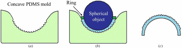
Figure 10. Fabrication process of MLAs on a curved shell. (a) Silanized concave PDMS mold. (b) Diagram showing a ring on the opening of the mold, liquid PDMS and a spherical object on the ring. (c) After curing, the spherical object and the ring were removed. We then peeled off the curved shell.
Download figure:
Standard image High-resolution image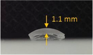
Figure 11. Cross section of the fabricated shell with MLA.
Download figure:
Standard image High-resolution imageThe experimental setup for measuring the optical quality of the curved MLAs is shown in figure 12. The laser light source went through the MLAs and generated focal spots of light on the detector. We rotated our MLA to find the maximum angle at which the MLAs can focus on the CMOS image sensor clearly. The experimental result is shown in figure 13. The incident light within 70° formed clear focused spots while focal spots of rays at larger incident angles failed to be captured by the image sensor. The FOV of the fabricated dome and shell were also calculated through their sizes. As we mentioned before, the opening angle was limited to the area of the spherical surface. Figure 14 shows the opening angles of the fabricated dome and shell. The red line shows the effective lens area of the shell. The opening angle of the shell decreases due to the width of the ring and reduces the effective lens area.

Figure 12. The experimental setup for testing the optical quality of the curved MLAs.
Download figure:
Standard image High-resolution image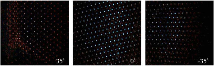
Figure 13. Focused spots captured by the CMOS image sensor at different incident angles.
Download figure:
Standard image High-resolution image
Figure 14. The possible opening angle of (a) the fabricated dome and (b) the fabricated shell. The red line shows the effective lens area of the shell.
Download figure:
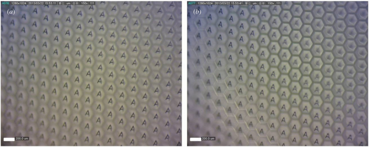
Standard image High-resolution imageFurthermore, we examined the imaging performance of the curved MLAs using a stereo microscope. The images created via the hexagonal microlenses at the top and on the sides of the dome are shown in figure 15. Since the microlenses were highly uniform, the focal plane of the curved MLAs would be nearly a spherical surface. Clear images of the letter 'A' are observed in the two figures with almost the same distance between the microlenses and the objective lens. However, when the distance was larger or smaller than the focal length, the letters became vague, as shown in figure 15(b). The sub-images at the edge area were blurred due to the mismatch between the distance of the microlens to the focusing plane and the focal length of the microlens. The resolution of each sub-image was limited to the pixel numbers of the CMOS image sensor. The experimental results demonstrate good imaging properties of the fabricated MLA.
Figure 15. Imaging performance of the curved MLAs captured by a stereo microscope. (a) Hexagonal MLAs at the top and (b) on the side of the dome.
Download figure:
Standard image High-resolution image
4. Conclusions
A simple method for fabricating PDMS MLAs on spherical surfaces was demonstrated successfully. The thermal reflowed hexagonal MLA of which the averaged diameter was 194.66 µm showed good uniformity. The measured focal length was 0.44 mm and the yield rate reached 99.5%. Through the use of a multi-replication process, the patterns of the microlens were transferred onto a curved PDMS surface successfully. The diameter and sag height of the spherical surface were 10 mm and 2.6 mm, respectively. The minimum radius of curvature we achieved was approximately 6.1 mm. Different radii of curvature could be available by changing the spherical object or tuning the pressing force. In other words, a smaller radius of curvature can be conventionally achieved using smaller spherical objects without any additional process. In comparison to previous work, this method is more accessible since neither special equipment nor a vacuum environment is required. Although multiple replication processes were required, each replication process with PDMS was simple and could be completed without clean-room requirements or high temperatures. Furthermore, once the curved mold with concave microlenses was fabricated, the curved MLAs could be replicated repeatedly without going through the whole process again. This saves time when a large amount of curved MLAs are required. In addition to surface quality, the uniformity of the curved MLA was also analyzed. The variation was low and surface roughness was lower than 20 nm. It was smooth enough for a refractive microlens. The results of the optical testing show good imaging performance of the fabricated curved MLAs. The theoretical viewing angle was 110°. The sub-images were clear and distinguishable. This experiment demonstrates the potential ability to fabricate omnidirectional arrayed optical components, which can be applied to compact mobile cameras in the future.
Acknowledgment
The authors would like to gratefully acknowledge the National Science Council of Taiwan for their funding support under NSC 101-2628-E-002-019-MY3.