
Abstract
In this work, we report on the electro-mechanical studies of high-Q spherical oscillators designed to operate in radio-frequency circuits. Resonating composite spheres, consisting of a silicon core and a thick nanodiamond shell, were studied by laser vibrometry in order to obtain mechanical quality factors and identify the resonant frequencies and eigenmodes of the system. Finite element method simulations were used to analyze and confirm the experimental data. Additionally, reflection/transmission measurements were carried out on capacitively coupled spheres in order to evaluate the electrical parameters of the system. The main aim of these investigations was to evaluate the potential of diamond-based spherical resonators to be used in modern communication devices.
Export citation and abstract BibTeX RIS
1. Introduction
The rapid evolution of wireless communications is generating a growing demand for high-performance reconfigurable radio frequency (RF) devices. Low-phase-noise frequency references and narrow-band-pass filters are the key elements for emerging miniaturized multi-band RF transceivers [1]. In modern RF devices, high-Q filters and reference oscillators are realized using off-chip micro-electro-mechanical system (MEMS) resonators, such as quartz crystals along with thin-film bulk acoustic resonators and surface acoustic wave piezoelectric devices [2, 3]. These bulky components are limited in their frequency range, but satisfy strict phase noise specifications. The superior advantage of MEMS resonators is their high quality factors (Q ∼ 104 − 105), which are orders of magnitude higher than those typical for conventional electronic components. A high Q contributes to improved frequency selectivity and phase stability along with a reduced level of insertion loss: IL ∼ ω0/(Q × Δω). For instance, a next-generation RF channel-select architecture requires <0.1% band-width filters, which can be realized using resonators with Q > 104.
Due to the material limitations of conventional silicon devices, wide band-gap semiconductor thin films, e.g. AlN [4, 5], SiC [6], ZnO [7] and diamond, were extensively explored for high (Q × f) MEMS resonators. For this purpose, diamond shows great advantages over other materials, mainly due to its exceptional mechanical properties, e, g. an acoustic velocity of v > 18000 m s−1 (v ∼ 8000 and ∼11500 m s−1 reported for Si and SiC, respectively) along with a low predicted fundamental phonon scattering rate [8]. Given that the resonance frequency is proportional to the acoustic velocity, diamond thin films appear to be the best choice for high-Q RF micromechanical resonators.
2. Diamond based MEMS resonators
Single-crystalline diamond (SCD) beam resonators, having Q values exceeding 3 × 10⁵ at 0.7 MHz, were recently demonstrated, showing promising results for emerging RF transducers [9]. However, SCD is too costly for most applications, and its use is rather limited by growth and processing issues. Fortunately, poly- (PCD) and nano- (NCD) crystalline diamond thin films, with physical properties approaching those of SCD samples, are available via chemical vapor deposition (CVD) on low-cost silicon substrates [10]. Flexural beam resonators based on PCD thin films were reported by Sepulveda et al demonstrating Q ∼ 105 at 0.3 MHz. These experiments were powered by detailed analyses of dissipation mechanisms in vibrating beams, in order to evaluate diamond as a potential material for high-Q RF MEMS applications [11].
The mechanical quality factor, Q, of a resonator is generally defined as:
where W and WD are the stored vibrational energy and the average dissipated power per cycle, respectively, and ω0 is the resonant angular frequency. Among the major loss mechanisms, (i) the resonator clamping losses (Qc−1) and (ii) the viscous gas damping (Qg−1) are the most prevalent for the case of flexural beams. For such resonators in either an air or fluid environment, the viscous damping usually dominates [12]. However, for vacuum levels of <1 mbar, the gas damping contribution is minimal and can be neglected [13].
Therefore, the clamping losses, defined as part of the vibration energy dissipated through elastic wave propagation into the substrate, can be identified as the dominant loss mechanism for the beams operating in a vacuum. A maximal achievable Qc depends, in this case, on the oscillator geometry. For instance, Qc = 0.34(L/h)3 is an approximation derived for a cantilever beam [14], where L and h are the length and the thickness of the beam, respectively. For more complicated resonator geometries, like disk-shaped oscillators, the analytical expression for Qc is of greater complexity, comprising the Q dependencies on the support beam's material, thickness and radius, along with the order of vibrational mode [15]. The intrinsic loss mechanisms (Qintr−1), of which thermo-elastic dissipation [16], phonon–phonon interaction [17], internal friction and surface losses (e.g. due to surface/interface roughness) are prevalent, are mostly material dependent and relevant for practical consideration if the two above-mentioned dissipations (Qc and Qg) are strongly minimized.
Recently, advanced forms of resonating devices were utilized in order to realize high-(Q × f) mechanical oscillators via a substantial reduction of extrinsic and intrinsic losses [15]. In particular, the 'radial contour mode' diamond disk resonators with 'material-mismatched' Si stems were demonstrated with Qs exceeding 104 at 1.51 GHz [8]. Employing the volume-conserving whispering gallery modes (WGM), Q values as high as 105 at 0.5 GHz were reported on similar structures manifesting a further reduction in anchor/clamping losses [18].
While WGMs are characteristic for cylindrically symmetric systems, the sectoral spherical modes (SSM) are their equivalent in spherically symmetric systems (see figure 1(a)). Therefore, the logical step in the further development of electromechanical WGM-based transducers is the use of sphere-shaped resonators, which represent an ideal volume/energy conserving form. WGMs in microwave [19] and optical [20] spherical oscillators have been extensively studied and well understood. However, there are only a few applied studies describing the electro-mechanical vibrations of solid spheres, mainly due to the difficulties in micro-fabrication and integration. Up to now, the major development of mechanical spherical resonators relates to gravitational wave antennas [21].
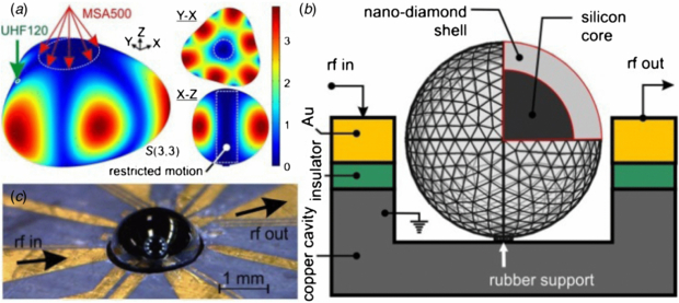
Figure 1. (a) The S(3,3) sectoral vibration mode calculated for a resonator sphere mounted onto a fixed point support. The color-coding represents the magnitude of total displacement. On top of the 3D view image, the measurement arrangements for MSA500 and UHF120 laser vibrometers are shown. (b), (c) The NCD based spherical resonator: (b) the oscillator design and excitation/measurement schema; (c) an optical image of the resonator sphere ( ∼ 2.27 mm) mounted in a 1.1 mm deep cylindrical copper cavity surrounded by Au/Cu radially-arranged electrodes emitting/receiving the RF-signal.
Download figure:
Standard image High-resolution imageThe vibrational modes of an uncoupled elastic sphere with uniform density ρ were considered in the classical work of Lamb [22]. Its eigenfunctions can be written in spherical coordinates (r, θ, φ) in terms of the Laplace spherical harmonics [23], Yℓm:

where indexes ℓ and m define the number of nodal lines in the latitudinal (ℓ − |m|) and longitudinal (|m|) directions, and eigenfunctions Anl(r) and Bnl(r) determine the sphere motion in the radial and tangential directions, respectively, which depend on the radius R and the material parameters (ρ, shear modulus µ, and Poisson ratio ν).
These parameters fully describe the vibration problem. If the sphere is disturbed, e.g. by a broad-band electro-magnetic (EM) signal, it begins oscillating with eigenfrequencies ωnℓm, and each spherical component of the EM field uniquely determines the effective force on the corresponding mode of the sphere. If the sphere is inhomogeneous, e.g. consists of a core and a shell made of different materials, and/or is supported by a stem, such a system cannot be treated analytically, and it is a subject of numerical simulations, e.g. by using a finite element method (FEM). The example of the FEM calculated, S(ℓ = 3, m = 3) vibrational mode carried out for the composite spherical oscillator is shown in figure 1(a). Such spheres, consisting of a silicon core ( ∼ 2.07 mm) and an NCD external shell (d ∼ 100 µm), have been studied in this work towards their resonant properties using laser Doppler vibrometry powered by FEM simulations and RF signal transient studies. The main aim of these investigations was to evaluate the potential of diamond based spherical resonators to be used as band-pass-filters and reference oscillators in modern communication devices.
3. Fabrication and experimental details
The NCD coated silicon spheres have been fabricated and chemo-mechanically polished using the technologies described in detail elsewhere [24]. Briefly, to obtain void-free, 100 µm thick NCD coatings, ultra-high-precision silicon spheres with a surface roughness <3 nm (rms) were placed in an ultrasonically agitated nano-diamond–methanol suspension. With this seeding method, nano-particle nucleation densities as high as 1014 m−2 have been achieved. A uniform NCD coating was applied by continuously rotating the Si spheres during the CVD process carried out in a gas mixture of 1% methane in hydrogen at a deposition temperature of 700–860 °C.
Following the polishing step, the spherical resonator was placed in the center of a cylindrical copper cavity (see figures 1(b), (c)), which was micro-machined in a specially designed RF chip equipped with radially arranged Au/Cu electrodes.
A soft-rubber-like support (Poisson's ratio ∼0.5) was used to fix the resonator in the center of the cavity in order (i) to minimize the support loss, and (ii) to realize conditions approaching the vibration of a support-free body. The gap of 150 µm separating the sphere equator and the electrodes was kept constant along the cavity circumference. The mechanical oscillations in the capacitively coupled resonator were excited using an electrical signal generated by either an external RF vector generator (R&S SMBV100A) or the internal generator of a network analyzer (R&S ZVL).
The mechanical resonant spectra were recorded using laser Doppler vibrometry. The scanning vibrometer (Polytec MSA500) was equipped with a 24 MHz displacement decoder with a resolution of <0.1 pm Hz−0.5, and a laser system having an optical output of <1 mW at λ = 620 nm. A single-point, ultra-high frequency vibrometer (Polytec UHF120) was equipped with a 1.2 GHz displacement decoder with an amplitude resolution of ∼2 pm. Its laser system allows for an optical output of ∼5 mW at λ = 532 nm and a spot size of  < 1µm.
4. Results and discussion
4.1. Mechanical vibration spectra
The technical characteristics of scanning and single point vibrometers used in these studies allow us to carry out two complementary kinds of measurements. The MSA500 is capable of scanning a restricted area on top of the sphere (figure 1(a)), acquiring the majority of low-index vibration modes including the zonal [S(ℓ, m = 0), no longitudinal variations] and partly the tesseral harmonics [S(ℓ, m ≠ ℓ)]. On the other hand, the sectoral harmonics [S(ℓ, m = ℓ), no latitudinal variations] have a very restricted motion along the z-axis. In order to detect the sectoral harmonics precisely, a UHF120 system was employed. Due to the high optical power and sub-µm spot size of the green laser, it allows for the detection of out-of-plane surface motion on the periphery of the sphere.
In figure 2, the experimental vibrational spectrum of a spherical resonator (in the bottom-half of the graph) is shown together with the FEM simulated spectrum (in the top-half of the graph). The vibrometry measurements and the simulations were performed on an ultra-precision NCD-shell/Si-core sphere. The resonator and materials parameters used for the evaluation are summarized in table 1. The experimental spectrum was measured by the scanning MSA500 vibrometer in the frequency range of 2–5 MHz with a resolution of ∼500 Hz. Amplitude averaging over 100 measurements was employed to collect all possible vibrational harmonics in one graph in order to compare the resonance positions with those appearing in the calculated spectra. As one can see in figure 2, the simulations fit the experimental data quite well, directly confirming the high precision of the resonator fabrication. In particular, characteristic doubled resonant peaks near the S(3,0) zonal mode at f3,0 ≈ 3.18 MHz, together with the f5,0 ≈ 4.8 MHz peak corresponding to the S(5,0) mode, can be used for precise mode identification. The peak positions and the quality factors of selected zonal modes S(ℓ,0) determined experimentally are shown in table 2. Q = f/Δf has been derived from a resonant peak fit using the Lorentz function, where Δf is the full width at half maximum of the resonance.
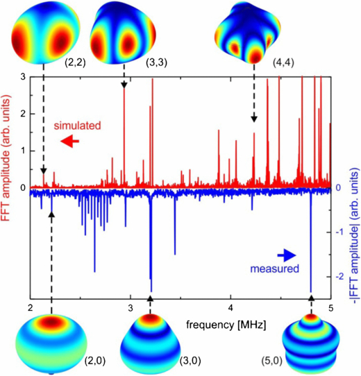
Figure 2. (a) The vibrational spectra of ultra-high-precision NCD-shell/Si-core spherical resonator with inner and outer diameters of 2.07 and 2.27 mm, respectively. The top half of the graph represents an FEM simulated spectrum; the bottom half of the graph shows the mirror image of the experimental one, recorded by a MSA500 vibrometer. Insets: the shapes of corresponding zonal [S(ℓ,0)] and sectoral [S(ℓ, m = ℓ)] modes used for the peak identification. The color-coding represents the magnitude of the total displacement field (in arbitrary units) of the oscillator body.
Download figure:
Standard image High-resolution imageTable 1. Parameters of the spherical resonator.
| Parameter | Si | NCD |
|---|---|---|
Sphere  , mm , mm |
2.070 | 2.270 |
| Young's modulus, GPa | 152 | 1050 |
| Shear modulus, GPa | 57 | 478 |
| Material density, kg m−3 | 2330 | 3550 |
| Poisson's ratio | 0.27 | 0.2 |
| Conductivity, Ω cm | 10–20 | N.A. |
Table 2. Properties of the selected spheroidal modes.
| Mode | Peak position, MHz Vibrom. | Q Vibrom. | Peak position, MHz Reflection | Peak position, MHz Transmission |
|---|---|---|---|---|
| S(2, 2) | 2.11 | 4860* | 2.08 | 2.15 |
| S(2, 0) | 2.22 | 2480 | 2.23 | 2.25 |
| S(3, 3) | 3.04 | 6902 | 3.07 | 3.04 |
| S(3, 0) | 3.20 | 3720 | 3.20 | 3.22 |
| S(4, 4) | 4.21 | 9355* | – | 4.22 |
| S(5, 0) | 4.85 | 4798 | – | 4.86 |
* derived from the spectrum shown in figure 3.
The results of a single-point vibrometry at the arbitrary lateral position relative to the z-axis of rotation are not straightforward for interpretation. As expected, the measured vibrational amplitudes depend strongly on the laser spot location and the local reflection conditions. The typical spectra obtained using the UHF120 vibrometer is shown in figure 3. Two sharp peaks, located at 2.11 and 4.21 MHz, correspond well to the sectoral S(2,2) and S(4,4) harmonics. The maximal Q ∼ 9300 has been achieved in air for the S(4,4) mode.
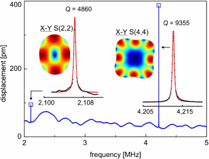
Figure 3. The out-of-plane vibrational spectrum of the spherical resonator recorded by the UHF120 vibrometer at the arbitrary lateral position. Insets: the fit of the resonant peaks shown together with the x–y plane cross-sections representing the (2, 2) and (4, 4) vibration modes. The resonant peaks were fitted using the Lorentz function in order to derive mechanical quality factors for the detected spheroidal S(ℓ, m) harmonics.
Download figure:
Standard image High-resolution imageThese SSM modes have a considerable in plane motion component, while the cylindrically-shaped central part remains relatively undistorted. The significant increase in Q-factor for a higher-order harmonic (see also table 2) is, therefore, related to the specific distribution of the displacement in the sphere [see figure 1(a) for the S(3,3)]. Similar to disk resonators oscillating in the WGMs, SSMs are generated around the equator of the sphere, inducing minimal motion at the cylinder volume centered at the z-axis of rotation. For higher index modes, more energy is confined near the surface, within the NCD shell, thereby reducing the intrinsic losses in the Si-core, and especially in the Si/NCD interface area, where non-diamond inclusions adversely alter the acoustic velocity. The discussion on the structure of the diamond/silicon interface can be found elsewhere [10].
4.2. Electrical reflectance and transmission
The characterization of the spherical resonator was accomplished by reflection and transmission electrical measurements using a broad-band RF signal generated and detected by a network analyzer. Here, we assume that the input impedance of the spherical resonator has a pure capacitive character with the reactance of Xc = (ωC)−1. Due to the enormous gap size of ∼130 µm, resulting in the measured capacitance of C ∼ 30–40 pF, the Xc value is high. Therefore, the resonator is not matched well to the 50 Ω network, and the electrical measurement precision is quite restricted. However, certain conclusions can be drawn that are based on the direct comparison of the impedance and vibrometry spectra.
Examples of normalized reflection and transmission spectra are shown in figures 4(a) and (b), while figure 4(c) displays an electrical equivalent circuit and device geometry for the measured resonator system. One can see that characteristic peaks in the reflection spectrum correspond well to the main vibration modes shown in figure 2 and also in table 2. This indicates a higher EM energy loss at the positions corresponding to the resonant frequencies of the sphere. The transmitted signal is shown in figure 4(b). The resultant resonant peak positions are listed in table 2. Similar to the reflected signal, all the peaks corresponding to the low-index mechanical spheroidal eigenmodes can be recognized in the spectra in the range of 2–5 MHz. Therefore, both reflection and transmission measurements fit reasonably well to the resonant data obtained by the laser vibrometry.

Figure 4. (a) Normalized reflectance and (b) transmission spectra of the spherical resonator system measured at a signal level of 20 dBm. Notes: only the selected zonal and sectoral modes are indicated in the spectra. (c), (d) The equivalent circuits and the device geometries shown for (c) the actual resonator and (d) prospective low-impedance system. [(1)-–RF input; (2)-–RF output; (3)-–Cu cavity/ground; (4)—Si core; (5)-–poly-C shell; (6)-–insulator film; (7)-–conducting stem].
Download figure:
Standard image High-resolution image
On the other side, the quality factors derived from the transmission spectra are difficult to evaluate due to the weak signal conditions altering the results. Therefore, for the current configuration of the transducer, we assume that the mechanical Q values obtained by laser vibrometry do not differ significantly from the values measured electrically (see, for instance, [25]).
5. Final remarks and conclusions
In summary, the mechanical vibrations of the composite diamond-shell/Si-core spherical MEMS resonators were precisely measured and thoroughly analyzed. In order to obtain the vibration properties approaching the support-free elastic sphere, the composite oscillators were mounted in the Cu-cavity using a soft-rubber-like support (ν ∼ 0.5). This method allowed for a convenient comparison of numerically simulated and experimentally recorded vibration spectra, along with a substantial decrease in support loss. It was demonstrated that due to the ultra-precision fabrication of the spheres, the calculated spectrum is in good agreement with the measured one, allowing for the exact identification of the vibrational modes.
It was also shown that the achievable quality factors strongly depend on the displacement distribution over the sphere volume, favoring the sectoral modes for use in high-Q devices. This is due to the specific nature of these modes, where mechanical SSMs are generated along the equator of the sphere shell (diamond), which induces minimal motion at the cylinder volume centered at the z-axis of rotation (consisting mostly of Si). Therefore, for the sectoral modes, the significant reduction of intrinsic/anchor losses in the Si-core and in the Si/NCD interface was achieved, resulting in mechanical Q ∼ 104, measured for the sectoral S(4,4) mode in air.
Much higher Q values might be achievable for SSMs in spherical resonators upon further improvements in the system design, which are presented in figure 4(d). Among them:
- –growth of a thicker shell should lead to the confinement of the high-order SSMs within the homogeneous nano-diamond layer, thereby further reducing the intrinsic losses in the Si-core and in the high defect density interface area (see the discussion in 4.1);
- –the high capacitive transducer impedance might be reduced by implementation of a conducting stem configuration, which would also allow for a precise self-centering of the sphere;
- –even further reduction of the capacitive impedance can be achieved by the scaling of the sphere–electrode spacing down to 100–150 nm using a self-centering technique, followed by 5–6 times enlargement in the electrode square.
Acknowledgments
The authors would like to thank S Klingelmeier, D Brink and O Kappeler for the technical assistance and to acknowledge funding from the German Research Foundation (DFG) within the research grants RF-CUBE & Säulenresonator.