
Abstract
We describe a photolithographic approach to create functional stimuli responsive, self-folding, microscale hydrogel devices using thin, gradient cross-linked hinges and thick, fully cross-linked panels. The hydrogels are composed of poly (N-isopropylacrylamide-co-acrylic acid) (pNIPAM-AAc) with reversible stimuli responsive properties just below physiological temperatures. We show that a variety of three-dimensional structures can be formed and reversibly actuated by temperature or pH. We experimentally characterized the swelling and mechanical properties of pNIPAM-AAc and developed a finite element model to rationalize self-folding and its variation with hinge thickness and swelling ratio. Finally, we highlight applications of this approach in the creation of functional devices such as self-folding polymeric micro-capsules, untethered micro-grippers and thermally steered micro-mirror systems.
Export citation and abstract BibTeX RIS
1. Introduction
The development of soft polymeric or hydrogel stimuli responsive actuators and related devices are important from both an intellectual and technological perspective [1–8]. Stimuli responsive soft-actuators are widely observed in nature, for example in the spontaneous and reversible folding and unfolding movements of plants. Examples include the Rhododendron leaves which respond to temperature [9] or the Dionaea muscipula (Venus flytrap) which responds to mechanical and pH stimulation [10, 11]. These actuators enable functions such as defense from predators or consumption of food which are critical to their survival. On the technological front, the development of such bio-inspired synthetic stimuli responsive soft devices could facilitate enhanced functionality for biosensing, robotics and surgery. Specific advantageous traits of these systems include the use of mechanical energy stored within the material, the ability to respond autonomously to enable smart behaviors, and the possibility for extreme miniaturization and untethered operation without the need for wires or batteries or external power sources.
Poly N-isopropylacrylamide (pNIPAM) is an important stimuli responsive hydrogel that undergoes a hydrophilic (swollen in aqueous media) to hydrophobic (deswollen) transition at a temperature just below physiological temperatures (LCST, between 32 °C and 36 °C) [12–16]. Further, when combined with other materials either by co-polymerization, blending or layering, these hydrogels can be made responsive to heat [17–36], pH [37], light [17, 19, 21, 25, 32], mechanical stress [28], ionic strength [37, 38] and magnetic field [35, 39]. Consequently, NIPAM based hydrogels have been used in soft-robotics [18, 24, 32, 35, 37–39], drug delivery [21, 22, 26, 27, 30, 31, 35] and surgery [28].
Despite these advances, the mass-production and miniaturization of such soft cross-linked hydrogel actuators can be challenging. Further, heterogeneous integration with conventional micro-electro-mechanical systems (MEMS) is often required for functional systems which necessitate the development of processes to pattern these soft materials using high resolution and high throughput techniques such as photolithography, imprinting and molding. Precise structuring of complex three-dimensional (3D) structures is also needed for practical applications. An emerging methodology that overcomes these challenges is the self-folding of precisely patterned hydrogel thin films [4, 6, 7, 29–38]. In these methods, existing planar lithographic approaches can be leveraged to create well defined patterns with high resolution and reproducibility. In contrast to previously described relatively higher temperature self-folding approaches for metallic or polymer patterns [40–42], self-folding of hydrogels can be accomplished at physiologically relevant temperatures in aqueous media. 3D actuation with large strains can be enabled by incorporating differential swelling of bilayers or films with compositional or cross-link gradients. For example, Klein et al showed how compositionally heterogeneous pNIPAM films could be used to create buckling sheets [23]. Ionov et al described thermo-responsive microcapsules based on pNIPAM-ABP/PCL bilayers [30, 31]. Kim et al demonstrated buckled gel surfaces using differential swelling of pNIPAM hydrogels using half-tone lithography [33, 34]. Bassik et al showed how pNIPAM-AAc/PEODA bilayers could be used to create flytrap like actuators [37].
Here, we demonstrate a new approach to create pNIPAM based self-folding systems as schematically represented in figure 1. Specifically, we utilized co-polymerized pNIPAM-AAc hydrogels which reduces the response time as compared to single component pNIPAM hydrogels due to increased hydrophilicity [43, 44] and the AAc component also makes the hydrogel pH responsive [45]. Our approach utilizes the fact that bending of hydrogel thin films depend on three important factors namely their thickness, modulus, and swelling ratio. We create two distinct regions within the hydrogel films; flexible hinges and rigid panels. In addition to being thinner, the flexible hinge also has a cross-link gradient [46] while the interconnecting panels are fully cross-linked and thicker. There are several advantages of our approach. As compared to many previous demonstrations of self-folding hydrogel actuators with bilayers, we use a single material that facilitates easy characterization and modelling for the homogeneous material. In addition, use of a single layer eliminates any risk of delamination that can be a concern in bilayer actuators. We demonstrate feasibility of our approach and discuss a finite element model that can be used to predict fold angle. As compared to previous methods such as half-tone lithography [33], the thinner gradient hinge provides increased flexibility and larger fold angles, as illustrated in the model. Finally, we highlight several applications to illustrate practical applicability of the approach.
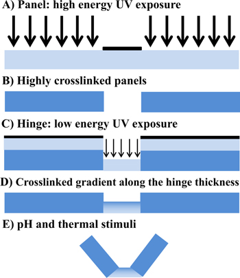
Figure 1. Illustration of the key steps utilized in creating 3D self-folding structures using thin, gradient cross-linked hinges and thick, fully cross-linked panels. (A)–(B) High energy UV exposed thick panels are fully crosslinked, while (C)–(D) low energy UV exposed thin hinges have crosslink gradients along their thickness. (E) On release from the substrate, and only when triggered by external thermal and pH stimuli, the patterns self-fold due to differential swelling and bending of the thin gradient cross-linked hinges.
Download figure:
Standard image High-resolution image2. Results and discussion
As illustrated briefly in figure 1 and in a more detailed manner in figure S15 , our fabrication approach utilizes two spin coating and two photopatterning steps; (a) low energy UV light exposure on thin hinges and (b) high energy UV light exposure on thick panels. Different types and combinations of patterns can be created by the appropriate design of photomasks for thick panels and hinges.
Details of the process are as follows. We thermally evaporated 20 nm of Cr adhesion promoting and 200 nm Cu sacrificial layers atop commercial silicon wafer substrates. We then spincoated (Specialty Coating Systems, G3P-8 model) the pNIPAM-AAc solution at 600 rpm to deposit the thick panels which were cross-linked by a high energy (500 mJ cm−2) UV exposure, through a mask that was appropriately designed using AutoCAD. We exposed the pNIPAM-AAc solution in non-contact mode by separating the mask from the substrate by thin spacers. We utilized a commercial mask aligner (ultra μline series: Quintel) with a 350 W mercury vapor lamp and the exposure energy was measured by multiplying the exposure time with the UV exposure intensity measured using a UV power meter (Vari-Wave II, 365 nm sensor; Quintel). After UV exposure, we developed the thick panels by immersion in acetone for around 7 s, rinsing with IPA and then drying using nitrogen gas. We then patterned the thin hinges using a similar process except that we deposited the film at a higher spin speed to create a thinner film. Also, we utilized a second low energy (50 mJ cm−2) UV exposure to photopattern a cross-link gradient along the thickness of the hinges. Then, we developed the hinges as before. We released the patterned panel and hinge structures by dissolving the Cu sacrificial layer in a commercial Cu etchant (APS 100; pH = 2). We observed that the samples could be stored and remained unfolded up to a year in APS 100. Self-folding was trigged only on exposure to the correct thermal or pH conditions.
In order to accurately target fold angles, we first measured post-cross-link thickness of rectangular test structures versus spin speed curves at the same UV exposure (500 mJ cm−2). We dispensed the pNIPAM-AAc hydrogel solution at six different spin speeds ranging from 600 rpm to 1200 rpm onto flat Si wafer substrates. We used a color 3D pinhole confocal optical microscope (KEYENCE VK-X100K) to image and measure the thicknesses of photopatterned pNIPAM-AAc test structures. Our thickness versus spin speed data is plotted in figure 2(A) and our data demonstrates that the thickness could be reproducibly controlled between thin 1.6 μm panels at the high spin speeds of 1200 rpm and thick 6.5 μm panels at low spin speeds of 600 rpm. We note that these films are thinner than the previously utilized pNIPAM self-folding structures which typically had thickness between 10 μm [33] and 225 μm [37]. We also measured the resolution of our photopatterning process using a ruler mask and the smallest feature that could be reproducibly patterned was 8 μm (figures 2(B), (C)). Color images in figures 2(D)–(F) show that different hinge and panel thickness could be implemented and also that the thickness within the fully cross-linked panels was relatively uniform.

Figure 2. Characterization of the pNIPAM-AAc hydrogel deposition and patterning process. (A) Thickness versus spin speed. The inset shows the test structure, and the scale bar is 1 mm. Images depicting the (B, C) resolution and (D–F) uniformity of photocrosslinking.
Download figure:
Standard image High-resolution imageBy varying the patterns of thick fully cross-linked panels and thin gradient cross-linked hinges using AutoCAD designed photomasks, we were able to create a variety of structures. After fabrication and release from the substrate, the planar photopatterned structures were heated up to 60 °C in the copper etchant APS 100 solution (pH 2). Illustrative examples of a self-folded pyramidal and cubic shaped capsule are shown in figure 3. The second and third columns in figures 3(A), (B) shows the intermediate and final self-folding steps. We observed that the yield was approximately 60% for well folded structures with no discernible defects when visualized by optical microscopy.

Figure 3. Schematic and optical microscopy images showing thermally responsive self-folding pNIPAM-AAc structures of different shapes such as a, (A) pyramidal, and (B) cubic shaped capsule. The optical images were taken using a NIKON AZ 100 microscope at pH 2 in APS 100 solution with increasing temperature from 25 °C to 60 °C. All scale bars are 300 μm.
Download figure:
Standard image High-resolution imageA key element of our approach is the creation of cross-link gradients on low UV exposure of 50 mJ cm−2. The influence of such low and high exposure energy is evident in the patterning of hole sheets shown in figures 4(A) and (B). Such sheets of identical thickness but exposed to low and high energy showed different self-folding characteristics. While sheets exposed to 500 mJ cm−2 buckle, they do not roll up due to the absence of a cross-link gradient (figure 4(C)). In contrast, identically shaped sheets patterned with a lower energy of 50 mJ cm−2 roll up due to a cross-link gradient along the thickness of the film (figure 4(D)). We characterized the cross-link gradients by adding a fluorescent dye (rhodamine 6 G) into the pNIPAM-AAc solution which was then sonicated for 30 min to form a well-mixed solution. The gradients in the films patterned with low UV exposure could then be visualized using confocal fluorescence microscopy (LSM 510 META, Zeiss). Specifically, we measured the relative pixel intensities from the top to bottom confocal images by depth discriminations and an intensity gradient was observed (figure 4(E)). This experimental data validates our approach of creating hinges with cross-link gradients for self-folding.

Figure 4. Characterization of the effect of UV energy exposure. (A)–(B) Optical and zoomed image of the holey test structure composed of a single pNIPAM-AAc panel. (C) Test structures exposed to high energy of 500 mJ cm−2 only buckled but did not roll up which we attribute to high crosslinking and absence of a cross-link gradient. (D) In contrast, test structures exposed to low energy of 50 mJ cm−2 rolled up indicating presence of a cross-link gradient. (E) Visualization of a cross-link gradient using confocal microscopy imaging of dyed low-UV exposed samples. Data shows a plot of the relative fluorescence intensity as a function of Z-section image stack. Larger confocal image numbers correspond to sections taken deeper into the sample. The low relative fluorescence intensity from these sections indicate a less-dense film (lower cross-linking). Scale bars are (A) 1.5 mm and (B–D) 300 μm.
Download figure:
Standard image High-resolution imageIn addition to experiments, we investigated the thermo-responsive deformation mechanism of the pNIPAM-AAc hydrogel via a 3D constitutive finite deformation model. The model assumes that the free energy change of the hydrogel system is caused by the mechanical stretching of polymer chains based on the classical Gaussian statistics and the polymer and solvent mixing based on Flory-Huggins model. Parameters of this model included the shear modulus and temperature-dependent Flory–Huggins interaction parameter. To determine the interaction parameter, the swelling mass ratio of cross-linked hydrogels was experimentally measured (figure 5). These measurements were carried out by spreading 500 μl pNIPAM-AAc solutions on a glass substrate, exposing the films to UV light with the relevant energies of 50 and 500 mJ cm−2 and soaking in DI water. We ensured that the samples reached equilibrium swelling by placing them on a hot plate at each temperature for at least 12 h.

Figure 5. Experimental (points) and simulation (lines) swelling ratios plotted as a function of temperature for low UV exposure (red circle, solid line: 50 mJ cm−2) and high UV exposure (blue square, dotted line: 500 mJ cm−2) energies.
Download figure:
Standard image High-resolution imageThe weight of the gel at this stage represents that of the swollen gel. The swelling ratio  was calculated by dividing the measured weight of the swollen gel at each temperature to that of the deswollen gel (dehydrated gel).
In addition to swelling ratios, the shear modulus of the swollen pNIPAM-AAc hydrogels was measured using a dynamic mechanical analyzer (Q800 DMA; TA instruments). The fully swollen samples exposed at high and low energies were both measured at room temperature in the dynamic mode, with a frequency sweep from 1 Hz to 10 Hz, and a 0.5% applied strain. The storage modulus was independent of the frequency and is equivalent to the equilibrium Young's modulus. The shear modulus G is related to the Young’s modulus E as:  where Ω0 is the swelling ratio at room temperature.
The constitutive model for the mechanical and swelling behavior of hydrogels is described below. Consider the deformation gradient, defined as F = ∂
x/∂
X, which describes the stretch and rotation of material lines from the dry stress-free body to the swollen and stressed body. The deformation gradient is decomposed into a mechanical part Fe and an isotropic swelling part Fs as  , where φ is the polymer volume fraction of the polymer-solute system at the swollen, stressed state. Since the gel is initially swollen, we define the initial swollen state as the stress-free reference state, and a deformation gradient f mapping the points from the stress-free reference state to the final spatial points:

where φ0 is the polymer volume fraction of the polymer-solute system at the reference state. The polymer volume fraction is represented as φ = 1/ (1 + vc) [47], where v is the volume per solute molecule and c is the number of solute molecules per reference volume. We define the left Cauchy-Green tensor as b = FFT and express it in terms of its eigenvalues (principal stretches) and eigenvectors (principal directions):

where  and
and  are the corresponding principal stretches of f. We assume that free energy density of the total system is caused by the stretching of polymer chains and the mixing of polymer and solvent, and is represented as:

We adopt a quasi-incompressible model for the free energy density associated with stretching polymer chains [48]
where G and κ are the shear modulus and bulk modulus respectively. We assumed the bulk modulus is 1000 times of the shear modulus to achieve the volumetric incompressibility of mechanical deformation.
The mixing component of the free-energy density is represented as [49, 50]

where R is the gas constant and χ is the Flory–Huggins interaction parameter. The Cauchy stresses tensor σ and the chemical potential μ can be obtained from the free energy [47, 51], as


Substituting equations (3)–(5) into equations (6) and (7) yields,
To model the thermo-responsive effect, we assumed that the temperature dependent Flory–Huggins interaction parameter χ has the following form [51],
where χL and χH are the Flory–Huggins interaction parameters at low temperature and high temperature respectively, Ttran is the transition temperature and ΔT is the width of the transition region. These parameters were obtained by fitting the simulation free swelling data to the experimental results as shown in figure 5. The parameters used in the model are listed in table 1.
Table 1. Parameters determined for the pNIPAM-AAc materials synthesized with different UV intensities.
| Parameters | G | χL | χH | Ttran | ΔT |
|---|---|---|---|---|---|
| 500 mJ cm−2 | 125 KPa | 0.595 | 0.98 | 34 °C | 5 °C |
| 50 mJ cm−2 | 74 KPa | 0.570 | 0.98 | 34 °C | 5 °C |
The constitutive model was implemented into TAHOE (Sandia National Laboratories) to simulate the self-folding pyramidal and cubic structures. Figure 6 shows the finite element model of the pyramidal specimen (the finite element model of cubic specimen is not shown). The mesh was discretized using trilinear hexahedral elements and a higher mesh density was chosen at the hinge. For simplicity, we modeled the gradient in the hinges as a two-layer structure where the top layer of the hydrogel has a higher cross-linker density and corresponding smaller swelling ratio (G = 90 KPa and χL = 0.58) compared with the bottom layer with a lower modulus and higher swelling ratio (G = 60 KPa and χL = 0.562). The parameters for the model were chosen to reproduce the modulus and swelling ratio measured for the 50 mJ cm−2 materials shown in table 1. The displacement boundary conditions were set as:


Figure 6. Finite element model of the pyramid specimen.
Download figure:
Standard image High-resolution imageThe simulation starts from stress-free state at temperature T = 25 °C, at which temperature the structure is unfolded as shown in experiments. The initial polymer fraction φ0 is obtained by solving equations (8) and (9) with the condition σ = 0 and μ = 0. The temperature is continuously increased to 37 °C. At each temperature, the deformation gradient f and polymer concentration φ are updated to satisfy the force balance and chemical potential equilibrium. From the simulation, we can obtain the folding angle as a function of temperature (figure 7(A); video S1A and B in supplementary5). To verify the model, we measured the folding angles of cubic structures. We did not measure the folding angle of the pyramidal structure because it was difficult to obtain an accurate angle from experiments. As shown in figure 7(A), the simulation shows good agreement with the experimental data. We also did a parameter study by changing the thickness of hinge. As expected, a thinner hinge yields a large folding angle as shown in figure 7(B). In the present study, the thinnest hinge we could reproducibly deposit by spin coating was 1.6 μm which was used. If alternate techniques such as layer by layer (LBL), surface initiated polymerization or self-assembly are used, then even thinner hinges could possibly be fabricated for even greater fold angles.

Figure 7. (A) Experimental and simulation results of the folding angle of pyramidal and cubic structures having 1.6 μm thickness as a function of temperature (corresponding video S1 A and B in the supplementary section5). (B) Simulation results of folding angles of the pyramidal structure having different hinge thickness of 0.8, 1.6, and 3.2 μm as a function of temperature. Thinner films show larger fold angles.
Download figure:
Standard image High-resolution imageSince, we can create a wide range of structures using this approach we highlight a few applications. In figure 8, we show self-folding of a cubic capsule that assembled on heating. Figures 8(A), (B) indicates the high-throughput nature of the process so that many structures can be patterned and assembled at once. Once assembled, the structures can be loaded with cargo such as the beads shown in figure 8(C). This example highlights possible utility of this approach to create self-folding capsules or microcontainers. Further, transparency of the pNIPAM-AAc faces permits visualization of the encapsulated cargo using optical bright field or fluorescence microscopy.

Figure 8. Parallel self-folding of cubic capsules with thick highly cross-linked panels and thin gradient cross-linked hinges. (A) Top view optical image of the self-folded capsules, (B) zoomed inset of a cubic capsule, and (C) image of a cubic capsule loaded with beads. One of the transparent beads is outlined with a red dotted circle to aid visualization. All scale bars are 350 μm.
Download figure:
Standard image High-resolution imageIn addition to capsules, we also highlight the combined thermally and pH responsive opening and closing of grippers (figure 9). The grippers were patterned with six symmetrical fingers and three joints in each finger. The grippers close in environments of pH 2, T = 60 °C and open in environments of pH 7, T = 25 °C. The reversibility of these pNIPAM-AAc grippers was tested over several folding to unfolding cycles and no phenomenological residual plastic deformation was observed under parallel stimuli triggers between (60 °C, pH 2) and (25 °C, pH 7) (supporting video S25). We did however observe that the soft digits sometimes adhered to each other or the underlying substrate.

Figure 9. pNIPAM-AAc hydrogel grippers. (A)–(C) Sequential snapshots showing closing (60 °C in pH 2) and opening (25 °C in pH 7) of a gripper around a 250 μm bead. Scale bars are, (A) 550 μm, (B) 650 μm, and (D) 400 μm. A video S2 is included in the supplementary section5.
Download figure:
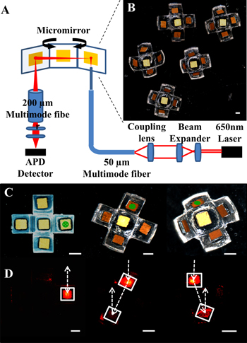
Standard image High-resolution imageFinally, stimuli responsive micro-mirror scanners were designed to demonstrate proof-of-concept applicability in optics (figure 10). Recently, much research has been directed at the design and fabrication of smart material based optomechanical micro-mirrors [52]. Additionally, micro-mirror elements have been widely used in optical systems such as flat panel displays, optical interconnects, adaptive optical arrays and laser beam scanners [53, 54]. They benefit from low weight, low operating optical power, compact design and sizes, which are potentially applicable to a variety of optoelectronic devices. We created five-faced pNIPAM-AAc structures with square (500 μm × 500 μm) Au mirrors that were attached using an epoxy. In order to highlight applicability of a thermally responsive micro-mirror steering system, we directed a beam of light at these structures. As depicted in figure 10(A), a 650 nm red laser beam was expanded and collimated by a beam-expander and the collimated beam was coupled into 50 μm diameter multimode fiber core by a microscope objective lens (Plan 10x/0.25, Olympus). The distal end of the fiber was directed toward the gold mirror mounted on the hydrogel actuator (figure 10(B)). The light reflected by the micro-mirror through the 200 μm multimode fiber was detected using an avalanche photodetector (APD110A, Thorlabs). When the structures self-fold in different environments, the position of the beam of light changes from reflection from a single mirror to two mirrors separated by different distances as can be seen in figures 10(C), (D). In the present design, the distance between incident and reflected beam vary from d = 0 mm to 2 mm. Hence, both the intensity and direction of the reflected beam varies with the environment (temperature, pH) and can be utilized for steering in optical beams or to decipher positional information. The advantages are that this approach is contactless and does not require wired connections or external power sources.
Figure 10. Stimuli responsive thermally steered optoelectronic micro-mirror system. (A) Schematic of micro-mirror system that utilizes a 650 nm laser and fiber optics. (B) Samples of 3D self-actuating systems composed of pNIPAM-AAc hydrogel actuators with gold micro mirrors. (C) Sequence of thermally responsive self-folding and (D) corresponding light incidence and reflection as depicted by the white lines and arrows. The white squares depict the Au mirrors. All scale bars are 500 μm.
Download figure:
Standard image High-resolution image
3. Conclusion
In conclusion, we have developed a new approach to enable self-folding stimuli responsive microstructures. Photolithographic patterning of thin gradient cross-linked hinges and thick fully cross-linked panels have enabled advanced functionalities such as capsules, grippers and stimuli responsive micro-mirrors. We anticipate widespread applicability in optics, electronics, and robotics. A predictive finite element model was used to rationalize fold angles and its variation with hinge thickness and swelling ratio. Our study also highlights several important challenges. Notably increasing the speed of actuation to the sub-second time scales remains challenging. Additionally, increasing the resolution of lithographic patterning such as by imprint techniques could enable smaller structures. Finally due to the low modulus of hydrogels, such actuators are floppy and additionally work primarily in aqueous environments. The inclusion of more rigid elements [36] and microfluidic interfaces could be used to further expand their capabilities.
4. Experimental
4.1. Materials
N-isopropylacrylamide monomer (NIPAM, Scientific Polymer Products Inc.), poly-N-isopropylacrylamide (pNIPAM, 300 k MW, Scientific Polymer Products Inc.), N, N-Methylenebis-Acrylamide (BIS-Acrylamide, Aldrich), n-butanol (Sigma), Irgacure 2100 (Ciba), acrylic acid (AAc, Aldrich), APS copper etchant 100 (Transene company, INC), Rhodamine 6G (Sigma Aldrich)
4.2. Synthesis of pNIPAM-AAc
The pNIPAM-AAc solution was prepared by dissolving 3 g NIPAM monomer, 0.4 g poly-N-isopropylacrylamide (pNIPAM) and 0.18 g cross-linking agent BIS-acrylamide in 7.5 ml of n-butanol organic solvent. In addition, 100 μm photoinitiator Irgacure 2100 and 0.31 ml pH responsive monomer of acrylic acid (AAc) were added in pNIPAM base. Finally, this pNIPAM-AAc solution was stirred using a magnetic bar for at least 6 h to dissolve completely.
4.3. Imaging of pNIPAM-AAc hydrogel structures
The pNIPAM-AAc hydrogel still images and videos were predominantly captured using a NIKON AZ100 multi-zoom microscope with an intensilight UV lamp and a motorized stage for Z-stack image layers. A KEYENCE VK-X100K color 3D confocal laser microscope was used to take images of photopatterned 2D hydrogel images for thickness measurements. In addition, a Zeiss LSM 510 META confocal microscope was used for Z-directional sectioning images to investigate photo-cross-linking gradients along the thickness of thin pNIPAM-AAc hydrogel.
Acknowledgement
This work was supported by the National Science Foundation grant NSF CBET-1066898 (to DHG).
Footnotes
- 5
Electronic supplementary information (ESI) available.