
Abstract
The combined control and energy harvesting characteristics of an autoparametric vibration absorber consisting of a base structure subjected to the external force and a cantilever beam with a tip mass are investigated. The piezoelectric sheets are attached to the cantilever beam to convert the vibrations of the base structure into electrical energy. The coupled nonlinear representative model is developed by using the extended Hamiton's principle. The effects of the electrical load resistance on the frequency and damping ratio of the cantilever beam are analyzed. The impacts of the external force and load resistance on the structural displacements of the base structure and the beam and on the level of harvested energy are determined. The results show that the initial conditions have a significant impact on the system's response. The relatively high level of energy harvesting is not necessarily accompanied with the minimum displacements of the base structure.
Export citation and abstract BibTeX RIS
1. Introduction
Autoparameteric vibration systems are characterized by nonlinear internal coupling that involves at least two modes. This coupling results in energy transfer from one mode of the system to another. As such, the secondary mode, which is unforced, draws the energy from the primary mode and undergoes sustained oscillations. For engineering applications, autoparameteric vibration systems have been proposed to suppress oscillatory motions of a primary mode that is externally excited by transferring its energy to another mode. Haxton and Barr [1] proposed an autoparametric vibration absorber by attaching a cantilever beam with a tip mass to a base structure that is subjected to external forcing. Their experimental validation showed that such an absorber is very effective when it comes to reducing the vibrations of the base structure undergoing resonance or near-resonance excitation. Cartmell and Lawson [2] revised the system by attaching a bar with a spring instead of a cantilever beam. Several other researchers [3–8] designed autoparametric vibration absorbers by attaching a pendulum to the base structure.
Recently, Kecik and Borowiec [9] proposed an autoparametric system with a pendulum and an excited nonlinear oscillator to harvest energy from the motion of pendulum. The energy was harvested through magnetic induction and the highest level of harvested voltage was noted in the resonant region. In this work, we investigate the benefits of harvesting energy from the autoparametric vibration absorber proposed by Haxton and Barr [1] by attaching a piezoelectric sheet to the cantilever beam. Besides having a system that can be used for reducing the vibrations of the basic structure and harvesting energy, the proposed setup can also be used to reduce the amplitude of the oscillations of the secondary mode. One challenge in the characterization of the response of this system is its inherent nonlinearities which can lead to varying responses over different operational regions.
So, we derive a nonlinear distributed-parameter model that includes harvesting energy from the autoparametric vibration absorber. The model is then used to analyze the effects of the amplitude and frequency of the external force and load resistance on the nonlinear responses of the harvester. The analysis is then used to determine the optimum load resistance not only to control the motion of the base structure but also to harvest energy. Details of the proposed harvester's design and derivation of the governing equations are presented in section 2. Moreover, a reduced-order model is derived using the exact mode shapes of cantilever beam. Linear analysis is performed to determine the effects of load resistance on the global frequency and coupled damping ratio of the cantilever beam in section 3. The nonlinear analysis is performed to determine effects of the external force and load resistance on the response of the harvester over a wide range of operating regimes in section 4. Conclusion is presented in section 5.
2. Governing equations and representative model
The combined control/energy harvesting harvesting system under investigation is based on the autoparametric vibration absorber which is similar to the one considered by Haxton and Barr [1]. This system consists of a base structure subjected to an external force F(t) and a cantilever beam with a tip mass Mt, as shown in figure 1. The cantilever beam is composed of one steel and two piezoelectric layers. The two piezoelectric sheets are bonded to both sides of the steel layer and connected in parallel with opposite polarity to an electrical load resistance. The base structure M undergoes a vertical displacement xd and has a stiffness kd and damping coefficient cd. One local coordinate x–y is fixed on top of the base structure. The attached cantilever beam with the length L mainly moves in the horizontal direction y(s) where s is the coordinate axis along the beam.

Figure 1. Schematic diagram of an autoparametric energy harvester.
Download figure:
Standard image High-resolution imageThe governing equation of the above system is derived by using the extended Hamilton's principle [10]:

where, T, V and  are respectively the kinetic energy, potential energy and virtual work due to nonconservative forces. The kinetic energy T and potential energy V are expressed as
where Mt and M are respectively the tip mass and mass of the base structure, L is the length of the cantilever beam, It is the rotational inertia of the tip mass relative to the tip of the cantilever beam, m is the mass of the beam per unit length and is given by: m =  and EI is the stiffness of the cantilever beam and is given by: EI =
 ![$\frac{1}{12}{b}_{1}{E}_{{\rm{s}}}{{h}_{{\rm{s}}}}^{3}+\frac{2}{3}{b}_{2}{E}_{{\rm{p}}}[{({h}_{{\rm{p}}}+\frac{{h}_{{\rm{s}}}}{2})}^{3}-\frac{{{h}_{{\rm{s}}}}^{3}}{8}]$](https://content.cld.iop.org/journals/0964-1726/24/11/115012/revision1/sms519006ieqn3.gif) . In the expressions of m and EI,
. In the expressions of m and EI,  and
and  are the respective densities of the steel and piezoelectric layers, hs and hp are the respective thicknesses of these layers,
  and
and  are the respective widths of multiple layers and
  and
and  are the Young's modulus of the steel and piezoelectric layers, respectively. The values of all these parameters, as used in this work, are shown in table 1.
Table 1. Physical and geometric properties of the energy harvester.
| Es | Steel Young's modulus (GN m−2) | 200 |
| Ep | Piezoelectric material Young's modulus (GN m−2) | 62 |

|
Steel density (kg m−3) | 7800 |

|
Piezoelectric material density (kg m−3) | 7800 |
| L | Length of the beam (mm) | 200 |

|
Width of the steel layer (mm) | 38 |

|
Width of the piezoelectric layer (mm) | 36.2 |
| hs | Steel layer thickness (mm) | 0.7 |
| hp | Piezoelectric layer thickness (mm) | 0.267 |
| Mt | Tip mass (kg) | 0.26 |
| M | Mass of base structure (kg) | 1 |
| It | Rotational modulus of inertia of the tip body (m3) |

|
| d31 | Strain coefficient of piezoelectric layer (pC N−1) |

|
 |
Permittivity component at constant strain (nF m−1) | 27.3 |
The nonconservative forces include the damping, external and electric forces. Thus, the virtual work due to nonconservative forces in Hamilton's equation (1) is written as

where Wele, Wdamp and  represent the virtual work due to the electric, damping and external forces, respectively. The virtual work due to the electric force Wele is given by [11]

where Mele is the moment due to the electric effect. For the case where the upper and lower layer are parallelly connected, it is given by
where V(t) is the voltage of the piezoelectric layer, H(s) is the step function,  is the piezoelectric stress coefficient and
  is the piezoelectric coupling term which is given by
  . Moreover, the virtual work due to the damping force
  and the external force
  are expressed as

where F(t) is the external force acting on the base structure, as shown in figure 1, and is assumed to be of the form  ,
,  is the damping force of the base structure and written as
  and
and  is the damping force of the cantilever beam whose expression [12] is:
  . In these expressions, cd is the damping coefficient of the base structure, cs and
  are respectively the viscous strain and air damping coefficients of the cantilevered beam and F and Ω are the amplitude and frequency of the external force, respectively.
Substituting the expressions for the kinetic energy T, potential energy V and virtual work  due to nonconservative forces into extended Hamilton's equation (1), the governing equations of the electromechanical system are written as
where  is the total mass of the multi-layered cantilever beam and calculated as
  , and N is representative axial force and given by
![$-{M}_{{\rm{t}}}{\displaystyle \int }_{0}^{L}\frac{{{\rm{d}}}^{2}}{{\rm{d}}{t}^{2}}[\frac{1}{2}{(\frac{\partial y(\eta ,t)}{\partial \eta })}^{2}]{\rm{d}}\eta -$](https://content.cld.iop.org/journals/0964-1726/24/11/115012/revision1/sms519006ieqn33.gif)
![${\displaystyle \int }_{{\rm{s}}}^{L}m{\displaystyle \int }_{0}^{\xi }\frac{{{\rm{d}}}^{2}}{{\rm{d}}{t}^{2}}[\frac{1}{2}{(\frac{\partial y(\eta ,t)}{\partial \eta })}^{2}]{\rm{d}}\eta {\rm{d}}\xi $](https://content.cld.iop.org/journals/0964-1726/24/11/115012/revision1/sms519006ieqn34.gif) .
.
To relate the mechanical and electrical variables, we use the Gauss law [13] which is expressed as

where  is the electric displacement vector and
  is the normal vector of the plane of the beam. The electric displacement component D2 is given by the following relation [11]:

where  is the axial strain component in the steel and piezoelectric layers and is given by
  ,
,  is the permittivity at constant strain. Substituting equation (9) into (8), we obtain the following strain–voltage relation:

To investigate the effects of different parameters on the performance of the parametric energy harvester, we use a distributed-parameter representation. To this end, we discretize the motions of the cantilever beam using the Galerkin approach and determine its exact mode shapes. We consider first the free vibrations of the cantilever beam, which leads to the eigenvalue problem. Therefore, we drop the damping, polarization and nonlinear coupling terms in the second expression of equation (7) and separate the horizontal displacement  into spatial and time variables according to

where  and
and  are the modal coordinates and shapes of the cantilever beam attached by the tip mass, respectively. The modal shapes are expressed as [14]

where A, B, C and D are coefficients to be determined from the boundary conditions. The linearized boundary conditions are written as
Substituting equation (11) into equation (13), we obtain the simplified boundary conditions
where the ' is used to indicate the derivative with respect to s. Furthermore, based on the linearized dynamic equations and boundary conditions, the eigenfunctions are normalized by the following expression:
where p and r are used to represent the vibration modes,  is the rth natural frequency of the cantilever beam, and
  is the Kronecker delta, defined as unity when p is equal to r and zero otherwise.
Based on our previous work [15], the frequencies of the second and third modes for a beam such as the one used here are much larger than the first one. In this work, we are interested in the frequency ratio of the first mode of the cantilever beam and the base structure being one half which causes the beam motion. As such, we use only the first mode shape to model and analyze the system. Substituting equation (11) into equations (7) and (10) and considering the first mode, the governing equations are reduced to
where the dot is used to indicate the derivative with respect to time t, x is a new variable whose expression is  where
where  is the static vertical displacement of the system and is given by
  ,
,  and
and  are respectively the mechanical damping coefficients of base structure and cantilever beam,
  is the natural frequency of the base structure and is given by
  ,
,  is the first natural frequency of the beam which can be determined from equation (15), the coefficients
  and Cp are respectively the piezoelectric coupling term and capacitance of the harvester which are given by
  and
and  , f is the nondimensionalized external force and is written by
  and
and  ,
,  and
and  are the nondimensionalized coefficients whose expressions are
  +
+  ,
,  +
+  and
and  +
+  .
.
3. Impact of harvester on global damping and frequency
By harvesting energy from vibrating elements, one is essentially adding damping to the system. As such, it is important to perform a global analysis whereby the effects of the load resistance and energy harvesting are accounted for. To determine the effects of energy harvesting on the global frequency and damping, we introduce the following state variables

and rewrite the governing equations (16) as

The linear matrix of the state variables is given by ![${\bf{B}}=\left[\begin{array}{ccccc}0 & 1 & 0 & 0 & 0\\ -{\omega }_{x}^{2} & -2{\xi }_{x}{\omega }_{x} & 0 & 0 & 0\\ 0 & 0 & 0 & 1 & 0\\ 0 & 0 & -{\omega }_{1}^{2} & -2{\xi }_{1}{\omega }_{1} & -{\theta }_{{\rm{p}}}\\ 0 & 0 & 0 & \displaystyle \frac{{\theta }_{{\rm{p}}}}{{C}_{{\rm{p}}}} & -\displaystyle \frac{1}{{{RC}}_{{\rm{p}}}}\end{array}\right]$](https://content.cld.iop.org/journals/0964-1726/24/11/115012/revision1/sms519006ieqn66.gif) .
.
The eigenvalues of this matrix are then used to determine the global natural frequency and damping of the coupled electromechanical system. The variations of these two parameters as a function of the load resistance are shown in figures 2(a) and (b). Figure 2(a) shows that the global frequency is nearly constant with a value of about  in the range of load resistances below
  . This value increases to about
  for
for  . The global frequency exhibits a strong dependence on the load resistance in the range between
  and
and  . As for damping, it shows a significant increase from about 0.004 for
  to about 0.02841 for R near
  . This increase is followed by an equally significant decrease for higher values of load resistance to settle near a constant value around 0.004 for
  . The dependence of the natural frequency and damping of the coupled system on the load resistance points to its importance when trying to optimize the harvested power. This is especially true if the interest is also in controlling the amplitude of the motion of the primary structure.

Figure 2. Variations of the (a) global natural frequency and (b) coupling damping ratio of the cantilever beam as a function of the load resistance R.
Download figure:
Standard image High-resolution image4. Impact of the external force and load resistance
The autoparametric vibration system without the piezoelectric sheets exhibits many interesting nonlinear phenomena. These phenomena are observed over different ranges for the amplitude and frequency of external force and the damping coefficient and frequency of the attached cantilever beam. A typical frequency response curve of the absorber/harvester considered here is shown in figure 3. The plot shows that the autoparametric vibration system exhibits jumps and hysteresis. Over specific ranges of the excitation frequencies, such as regions B and D, there exits multiple stable solutions depending on the amplitude of the initial displacement. The red dashed lines in these regions represent the unstable solutions as determined by the method of multiple scales. For initial displacement amplitudes that are below the red lines, the oscillations decay to zero. For initial displacements that are above the red line, the amplitude of the oscillations converge to a nonzero stable solution, as indicated by the arrows. In region C, there is only one nonzero stable solution irrespective of the initial displacement. Regions A and E exhibit decaying solutions to the zero value.
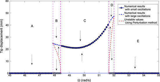
Figure 3. Frequency-response curves of the root mean square (rms) values for horizontal displacement of tip mass for the case of the load resistance  , the external force
  and the natural frequency of the base structure
  .
.
Download figure:
Standard image High-resolution image4.1. Effects of the amplitude of external force
We first analyze the effects of the amplitude of the external force on the nonlinear response of the energy harvester. We consider different load resistances for three cases of frequencies of the external forcing and natural frequencies of the base structure. In case 1, the excitation frequency is set slightly below the natural frequency of the base structure with  and
and  . In case 2, both frequencies are set equal, i.e.
  . In the third case, the excitation frequency is set higher than the natural frequency of the base structure with
  and
and  . The choice of these different values is based on the fact that the frequency response is highly dependent on the sign and magnitude of the detuning between the excitation and natural frequencies. All other parameters are fixed as shown in table 1.
Figure 4 shows the variations of the root mean square (rms) values of the displacements of the base structure and tip mass, harvested voltage and power with the amplitude of the external force. The plots show these variations for different values of load resistances and small and large displacements when the excitation frequency, Ω, is 49 rad s−1 and the natural frequency of the base structure is 50 rad s−1. The solid lines correspond to the responses of the energy harvester for the case of small displacements. The dashed lines correspond to responses for the case of relatively large displacements. For all values of considered load resistances, we note a hysteresis whereby relatively high levels of harvested energy can be realized with smaller excitation amplitudes when the system is subjected to relatively large initial displacements.
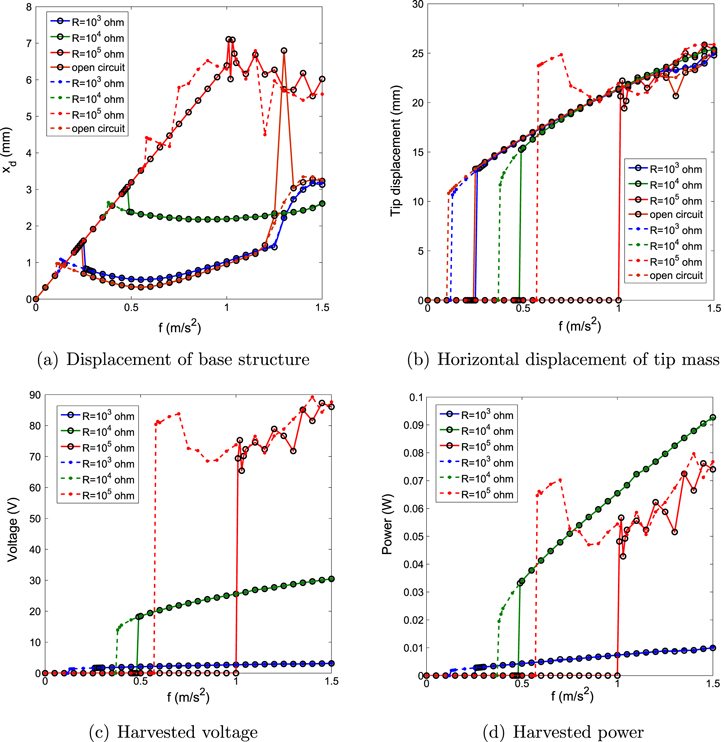
Figure 4. Variations of the root mean square (rms) values for (a) displacement of base structure, (b) horizontal displacement of tip mass, (c) harvested voltage and (d) harvested power as a function of the external force f with different load resistances and initial displacements for the case of the natural frequency of the base structure  and the excitation frequency
  . The circle–solid lines correspond to the small initial displacements and the point–dashed lines correspond to the cases of the large initial displacements.
Download figure:
Standard image High-resolution imageA comparison of the effects of the load resistance shows that the energy can be harvested at low amplitudes of the external forcing when  . However, the level of harvested power is significantly larger when
  and
and  at the relatively higher forcing amplitudes. This is consistent with the notion that energy harvesting contributes to the damping of the motion at these load resistances as noted in figure 2. In the case of
  , the energy harvester, when activated by large initial displacements, can generate energy at excitation amplitudes, f, that are as low as
  . This value changes to
  for small initial displacements. Of particular interest is a comparison of the systems responses in terms of energy harvesting and control of the displacement of the base. The open circuit configuration (no energy harvesting) yields the smallest displacement over a broad range of excitation amplitudes except for the range between 1.2 and
  where the base displacement is quite large. The case of
  shows a significant control of the base displacement that matches that of the open circuit configuration over the whole range and does not show the large response of the excitation amplitude between 1.2 and
  . This shows that the energy harvesting is actually helpful in the control of the displacement of the base structure over a broader range than that of the open circuit configuration. For the case of
  , the system yields the highest level of energy harvesting over a broad range of excitation amplitudes. However, the base displacement is much larger than that of the open circuit and
  configurations. That is mainly due to the fact that the enhanced damping ratio, which is highly dependent on the load resistance as shown in figure 2, is associated with the level of harvested power. These results show that the system can be configured depending on its purpose. Particularly, the load resistance can be varied to harvest a relatively high level of energy, to have a minimum base displacement over a broad range of excitation or to balance the level of harvested energy with the displacement of the base structure.
The system's nonlinearities also show different types of responses. Figure 5 shows time histories of the displacement of the base structure for different excitation amplitudes and load resistances. A comparison of the plots in figures 5(a) and (b) shows that the system's response changes from having one period to having multiple periods as the excitation amplitude is increased from  to
to  for the case of
  . This indicates the system undergoes bifurcations as the amplitude of the forcing changes. A comparison of the plots in figures 5(b)–(d) shows that the response changes in terms of its period content when the load resistance is varied or for the case of open circuit. Again, this indicates the system undergoes some bifurcations as the load resistance is changed.
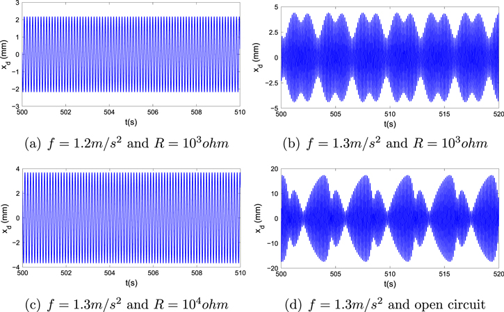
Figure 5. Time histories for displacement of base structure with the small oscillations for the case of the natural frequency of the base structure  and the excitation frequency
  .
.
Download figure:
Standard image High-resolution imageFigure 6 shows the variations of the rms values of the displacements of the base structure and tip mass, harvested voltage and power as functions of the external forcing amplitude for the case of perfect resonance between the excitation and natural frequency of the base structure, i.e.  . The plots do not exhibit the hysteresis response observed in the case of
  and
and  . The initial displacements do not impact the response of the harvester or masses. The plots also show that the activation of the motion and energy harvesting takes place at very small values of forcing amplitudes. Still, the plots show that the harvested energy is larger for
  than for
  or
or  . Of interest is the fact that although the level of harvested power is larger in the case of
  , the displacement of the base is minimum for the case when
  at high excitation amplitudes. In the range slightly below
  , this displacement is actually larger than in the cases of
  and
and  . These results show the importance of performing a global analysis of the coupled system.
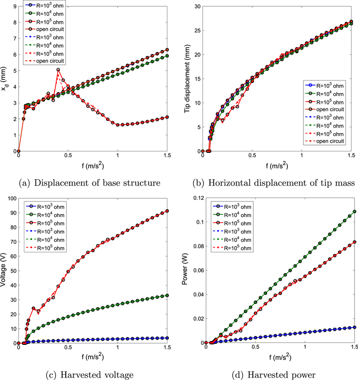
Figure 6. Variations of the root mean square (rms) values for (a) displacement of base structure, (b) horizontal displacement of tip mass, (c) harvested voltage and (d) harvested power as a function of the external force f with different load resistances for the case of the natural frequency of the base structure  and the excitation frequency
  . The circle–solid lines correspond to the small initial displacements and the point–dashed lines correspond to the cases of the large initial displacements.
Download figure:
Standard image High-resolution imageFigure 7 shows the same variations as in figures 4 and 6 but for the case of  and
and  . The plots show a hysteresis similar to the one observed in figure 4. As for the effects of the load resistance and displacement, we observe the same trends observed in the other conditions. To harvest the highest level of energy, it is better to choose a load resistance of
  than
than  and
and  . This is expected because the highest coupled damping is near that value. The case of
  leads to the lowest response amplitude of the base structure over a broad range of f. As such, if the system is to be used for control and energy harvesting, it may be better to use
  than
than  because it provides a more effective control except for a small region in the case of perfect resonance. Both figures 6 and 7 show that smaller base and tip mass displacements are obtained when harvesting energy in comparison to the case of the open circuit. As such, it can be concluded that harvesting energy from this system can effectively help in the control of both base and tip mass motions.
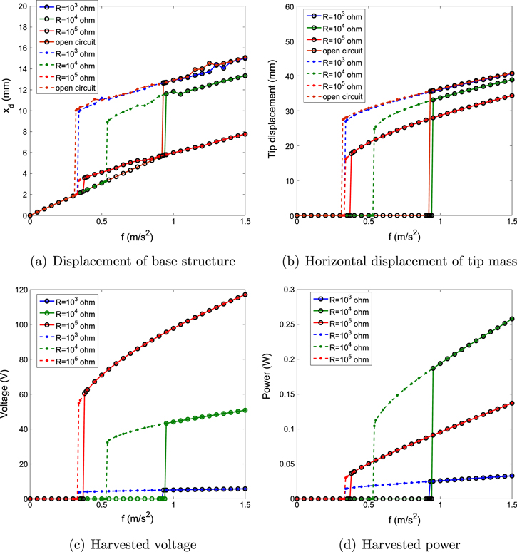
Figure 7. Variations of the root mean square (rms) values for (a) displacement of base structure, (b) horizontal displacement of tip mass, (c) harvested voltage and (d) harvested power as a function of the external force f with different load resistances for the case of the natural frequency of the base structure  and the excitation frequency
  . The circle–solid lines correspond to the small initial displacements and the point–dashed lines correspond to the cases of the large initial displacements.
Download figure:
Standard image High-resolution image4.2. Effects of the excitation frequency
The above results have shown that the excitation frequency impacts the responses of the mass and level of harvested energy. Next, we present frequency-response curves of the displacements of the base structure and tip mass, harvested voltage and harvested power. The plots in figure 8 show the response of the system when  and
and  . All other parameters are fixed as shown in table 1. Compared with the energy harvesting from direct base excitation [11], the autoparametric vibration system has a broader range over which energy can be harvested. This is especially true if the system is activated by large initial displacements. For instance, energy can be harvested over the range of excitation frequency between
  and
and  when
when  . Moreover, the rms value of harvested energy remains large even if the excitation frequency is shifted from the natural frequency of the base structure (away from the resonance). The plots also show that higher power levels are harvested when
  than when
  or
or  . This is expected because the damping ratio at
  is larger than that at
  or
or  as shown in figure 2 and the higher damping ratio is associated with higher levels of energy harvesting. When control for the motion of the base structure is of interest, the small load resistance (i.e.
  ) is a better choice when the external frequencies relatively small while the large load resistance, such as
  , is more suitable for the larger external frequency. This is due to the fact that the natural global frequency is a function of the load resistance which affects the efficiency of the energy transfer to the beam.
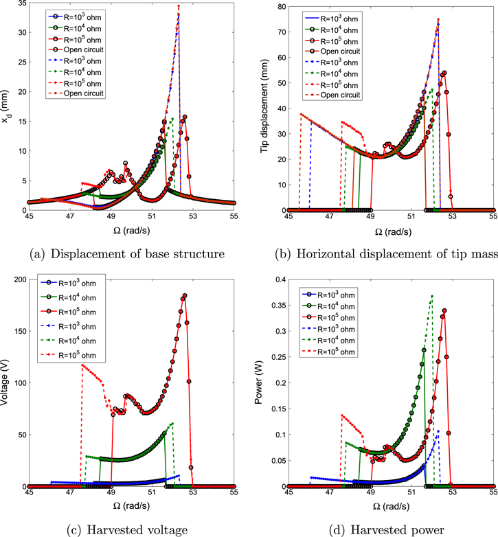
Figure 8. Frequency-response curves of the root mean square (rms) values for (a) horizontal displacement of base strucutre, (b) displacement of tip mass, (c) harvested voltage and (d) harvested power with different load resistances and different initial displacements for the case of the external force  and the natural frequency of the base structure
  . The circle–solid lines correspond to the small initial displacements and the point–dashed lines correspond to the cases of the large initial displacements.
Download figure:
Standard image High-resolution imageFor the case of  , we note that the response of the system exhibits different characteristics in the frequency range between 48.6 and
  . The time histories presented in figure 9 show a change from a periodic response for
  to a modulated one for
  and more chaotic one in the range between 49 and
  . The response reverts back to modulated and periodic ones as the frequency is increased to 50.5 and
  , respectively. We note that the maximum amplitudes of these responses are larger when the response is chaotic than when it is periodic. This results in the variations of the rms amplitude of the oscillations observed over this specific range in figure 8.
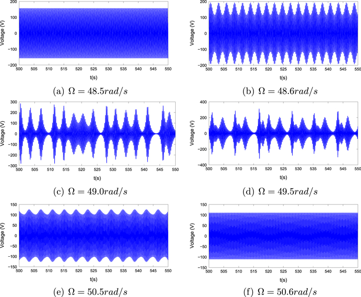
Figure 9. Time histories for the harvested voltage with the large oscillations for the case of the natural frequency of the base structure  and the external force
  .
.
Download figure:
Standard image High-resolution image4.3. Effects of the load resistance
We determine the effects of the load resistance on nonlinear responses of the system for different external forces and initial displacements. We consider the same three cases of section 4.1. Figure 10 shows variations of the displacements of the base structure and tip mass, harvested voltage and harvested power as the functions of the load resistance when  and
and  . The external forces f are chosen as 0.5, 1 and
  . When the external force is small (
 ), the system cannot harvest energy with the small initial displacements and large load resistances (
 ). This can be explained by the fact that the amplitude of the motion of the base structure is not large enough to overcome the enhanced damping and/or the increase in the global frequency of the cantilever beam by the load resistance, as shown in figure 2. In this case,
  is an optimum choice of the load resistance for the purposes of controlling the motion of the base structure and harvesting relatively high energy. Moreover, the range of the load resistance, in which the system can harvest energy, increases as the external force is increased. Considering the case of
  , the autoparametric vibration absorber with the small initial displacements can harvest energy when
  or
or  . If the system is activated by large initial displacements, electric power can be harvested with all load resistances. For the case of
  , the system can harvest energy over a broad range of load resistance with small initial displacements. This is expected because the onset external force to activate the horizontal motion of cantilever beam increases as the damping ratio of the cantilever beam is increased. As such, the load resistance has a significant impact on the performance of energy harvesting from an autoparametric vibration absorber because the global frequency and damping ratio of the cantilever beam are strongly dependent on load resistance, as shown in figure 2.
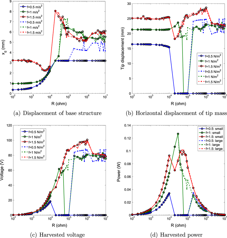
Figure 10. Variations of the root mean square (rms) values for (a) displacement of base strucutre, (b) horizontal displacement of tip mass, (c) harvested voltage and (d) harvested power as a function of the load resistance R with different external forces f and initial displacements for the case of the natural frequency of the base structure  and the excitation frequency
  . The circle–solid lines correspond to the small initial displacements and the point–dashed lines correspond to the cases of the large initial displacements.
Download figure:
Standard image High-resolution imageFigure 11 shows the effect of the load resistance on the nonlinear responses of the energy harvester when  and
and  . Inspecting figure 11, we note that the performance of the energy harvester is almost independent on the initial displacements. However, the load resistance significantly impacts the response of the system. The rms displacement of the base structure first decreases then increases as the load resistance is increased. Significant fluctuations in the rms values are observed at high values of load resistance. When the external force is small, such as
  , the minimum displacement of the base structure and the maximum harvested power are obtained at the same load resistance (
 ). As the external force is increased to
  , the rms displacement of the base structure reaches the minimum value of 1.6 mm with the load resistance
  . This displacement of base structure is even smaller than the minimum value for the case of
  . As the external force is increased further to
  , a minimum displacement of the base structure is obtained when a large load resistance is chosen. Therefore, the motion of the base structure can be better controlled with energy harvesting especially when the external force becomes relatively large.
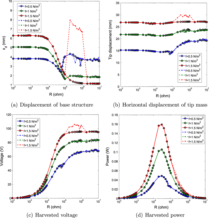
Figure 11. Variations of the root mean square (rms) values for (a) displacement of base strucutre, (b) horizontal displacement of tip mass, (c) harvested voltage and (d) harvested power as a function of the load resistance R with different external forces f and initial displacements for the case of the natural frequency of the base structure  and the excitation frequency
  . The circle–solid lines correspond to the small initial displacements and the point–dashed lines correspond to the cases of the large initial displacements.
Download figure:
Standard image High-resolution imageThe variations of the performances of the system as a function of the load resistance when  and
and  are shown in figure 12. We note that the energy harvesting is useful to control both the motions of the base structure and tip mass with the large load resistance. This response can be exploited by designing an energy harvester with the condition that the natural frequency of the base structure is a slightly larger than the excitation frequency. Moreover, the load resistance around
  is the optimum load resistance for the purposes of controlling the base structure and energy harvesting when the external force is relatively large, such as
  and
and  .
.

Figure 12. Variations of the root mean square (rms) values for (a) displacement of base strucutre, (b) horizontal displacement of tip mass, (c) harvested voltage and (d) harvested power as a function of the load resistance R with different external forces f and initial displacements for the case of the natural frequency of the base structure  and the excitation frequency
  . The circle–solid lines correspond to the small initial displacements and the point–dashed lines correspond to the cases of the large initial displacements.
Download figure:
Standard image High-resolution image
5. Conclusion
In this work, we investigated the combined control and energy harvesting characteristics from an autoparametric vibration absorber consisting of a base structure subjected to the external force and a cantilever beam with a tip mass. To convert the vibrations into electrical power, two piezoelectric sheets were bonded to both sides of cantilever beam and connected in parallel with opposite polarity with a load resistance. A coupled nonlinear distributed-parameter model was developed based on the extended Hamilton's principle to characterize the nonlinear interaction between the cantilever beam and base structure. Using the Galerkin approach, we discretized the motions of the cantilever beam and determined its exact mode shapes. A linear analysis was performed to determine the effects of the electrical load resistance on the global frequency and damping ratio of the cantilever beam. Then, a nonlinear analysis was performed to investigate the effect of amplitude and frequency of the external force and load resistance on the characterizations of the harvester. The results showed a strong interaction between the control and energy harvesting levels of the system. The global damping and natural frequency are significantly impacted by adding the harvester. Hence, the range and amplitude of excitations over which both control and energy harvesting can be effective is impacted. A strong dependence of the system's response on the initial displacements is also noted. In addition to these practical observations, we noted that the system exhibits interesting nonlinear phenomena, such as, saturations, jumps and hystereses.