
Abstract
This paper describes how an inerter-based device for structural vibration suppression can be realized using an electromagnetic transducer such as a linear motor. When the motor shaft moves, a difference of voltage is generated across the transducer coil. The voltage difference is proportional to the relative velocity between its two terminals. The electromagnetic transducer will exert a force proportional to current following the Lorentz principle if the circuit is closed around the transducer coil. If an electronic circuit consisting of a capacitor, an inductance and a resistance with the appropriate configuration is connected, the resulting force reflected back into the mechanical domain is equivalent to that achieved by a mechanical inerter-based device. The proposed configuration is easy to implement and very versatile, provided a high quality conversion system with negligible losses. With the use of electromagnetic devices, a new generation of vibration absorbers can be realized, for example in the electrical domain it would be relatively uncomplicated to synthesize multi-frequency or real time tunable vibration absorbers by adding electrical components in parallel. In addition by using resistance emulators in the electrical circuits, part of the absorbed vibration energy can be converted into usable power. Here an electromagnetic tuned inerter damper (E-TID) is tested experimentally using real time dynamic substructuring. A voltage compensation unit was developed in order to compensate for coil losses. This voltage compensation unit requires power, which is acquired through harvesting from the vibration energy using a resistance emulator. A power balance analysis was developed in order to ensure the device can be self sufficient. Promising experimental results, using this approach, have been obtained and are presented in this paper. The ultimate goal of this research is the development of autonomous electromagnetic vibration absorbers, able to harvest energy, convert it into usable power, and use it for vibration control and health monitoring.
Export citation and abstract BibTeX RIS

Content from this work may be used under the terms of the Creative Commons Attribution 3.0 licence. Any further distribution of this work must maintain attribution to the author(s) and the title of the work, journal citation and DOI.
1. Introduction
Reduction of structural vibration is a major engineering research field in the quest to manufacture more accurate, durable, flexible and lighter systems. Many passive devices have been developed in the last century, for example Den Hartog's tuned mass damper (TMD) [1]. A wide variety of mechanical dissipaters have been proposed: base isolation, bracing, friction-viscoelastic dampers, to recently proposed inerter-based devices, such as the tuned inerter damper, (TID) [2]. Passive devices are unable to adapt to changing and are often very sensitive to mistuning [3]. In contrast, active devices can adapt to different conditions at the cost of energy usage, hardware costs and stability and reliability issues. Semi-active schemes achieve a compromise between the two by combining the reliability of passive systems with a certain degree of adaptability at lower energy cost. A recent review can be found in [4] and novel semi-active schemes can be found in [5, 6], for example. A key component missing in the available research for vibration suppression is the issue of developing such systems at minimum energy usage. Most research focuses on performance at the expense of power consumption. In this research, the efforts are directed toward an energy efficient approach. Our proposed device, an electromagnetic tuned inerter damper, with internal energy harvesting, offers the possibility of adapting parameters at ideally no energy cost.
The inerter was proposed a decade ago by Smith [7] and represents the mechanical equivalent of a capacitor, using the force–current analogy between mechanical and electrical networks. Its constant of proportionality is called inertance and is measured in kg. Different networks for inerter-based devices have been studied in the last few years [8], mainly for applications in the motor racing industry, where inerters are known as J-dampers [9], and in railway vehicles suspensions [10]. In [11] the electrical-mechanical analogy of different networks using inerters was presented, for application as passive suspensions in vehicles. However, recently, the inerter has been used as part of vibration supression systems for structures [2, 12]. Of specific interest here is the tuned-inerter-damper (TID) configuration proposed in [2]. In this study, the TID behaviour was modelled and compared numerically with a traditional TMD in a multi-storey building subjected to sinusoidal and earthquake loads. The work concluded that, the potential advantages if a TID over a traditional TMD, can be summarized as follows.
- (1)The TID is lighter due to gearing ratios [7].
- (2)Its optimal position is at the bottom of the building rather than at the top as is the case with a TMD, so reducing the structural loads.
- (3)A TID reduces not only response at resonance but a higher frequencies since the TID behaves as a damper at higher frequencies. This is highly advantageous for multiple degree of freedom (DoF) systems.
Energy harvesting from vibration can be realized through three basic mechanicms: electromagnetic, electrostatic and piezoelectric transductions. Electromagnetic and piezoelectric transducers have been widely used in power generation or harvesting applications [13–15]. Generally speaking piezoelectric transducers are more appropriate for microscale systems, as they are easily integrated into silicon devices [16, 17], while macroscale devices are readily fabricated using high performance bulk magnets and multiturn coils, [14]. In the last decade interest has grown in employing electromagnetic devices for structural vibration control. Early works focused in the possibility of using electromagnetic dampers [18]. The idea was to substitute the damper on a TMD for a electromagnetic device, capable of energy dissipation externally to the device, avoiding problems as overheating. In [19], the authors study analytically and experimentally the possibility of developing a vibration absorber using an electromagnetic resonant shunt damper, consisting on a series LCR circuit. Optimisized values for the electrical circuit were derived and sensitivity to parameters error was studied. The authors concluded than their device offers a better vibration suppression effect than a traditional shunt damper, consisting of only the resistance. In [20] the dynamic analogy between an electromagnetic shunt damper, consisting of a series LCR circuit and a TMD was presented. They concluded the electromagnetic device offers similar dynamic performance than the mechanical TMD. Later research works studied combining energy harvesting and vibration suppression [21–23]. In all of these studies, the damper of a TMD, or part of it, is substitute by an electromagnetic device connected to a resistive load. By using a resistance emulator unit part of the absorbed energy can be converted into usable power [24]. Going a step further, more recently, the idea of synthesizing electrically all the elements in a mechanical TMD, combining vibration suppression and energy harvesting, have been studied [25]. In [25] the damper in the TMD was replaced with an electromagnetic transducer shunted with a resonant RLC in series, which produces a two DoF TMD, one (DoF) mechanical and the other one electrical. They compare the performance of the proposed electromechanical device with the traditional mechanical one, although these are not directly analogous, since the mass and the capacitor are not equivalent [7]. This study was pure numerical and no losses in the coil were included in the study.
In this paper, we further develop the idea an electromagnetic vibration absorber [19, 20, 25]. We consider an electrical implementation of a TID vibration supressor, consisting of an electromagnetic device connected to an electrical load. The load emulating the TID consisted of a resistor and a inductor in parallel connected to a capacitor. This is shown to have superior performance to the RLC circuit used in [20, 25]. An additional feature we propose is to use a resistance emulator, instead of a passive resistor, that allows energy harvesting [24]. The reduction of performance of the proposed device due to losses in the electromagnet coil is studied. A voltage compensation unit is proposed to counteract for the losses in the coil. Since this voltage compensation unit needs to be powered, a power balance study is developed to ensure than more usable power is produced via the resistance emulator than is needed by the power compensation unit, as the final goal is to develop an autonomous device that needs no external power.
The paper is structured as follows, first we present the equivalence between the mechanical TID and the electrically synthesized device E-TID. The advantage of connecting some of the elements in parallel is explained. In the third section the E-TID coupled with a host structure is studied and the optimal parameters of the electrical circuit are derived, when the objective is the reduction of the maximum displacement of the host structure. Section 4 studies the effects caused by the resistance of the coil in the electromagnetic transducer and presents a voltage compensation unit to counter for for the losses when they became critical. In the same section, since the compensation unit needs to be charged, a power balance study is developed, in order to ensure that we can work in net power generation scenario, that is, the device does not need more power that it is able to produce. Section 5 presents the tested rig and experimental results, finally conclusions are drawn in section 6.
2. Electromagnetic tuned inerter damper
The TID device presented in [2], is depicted in figure 1, connected to a host structure. The force exerted by the TID to the host structure, in Laplace domain, is given by:
where kd, cd, bd are the stiffness, damping and inertance of the TID respectively and FTID(s) and X(s) the Laplace transforms of fTID(t) and x(t) respectively.
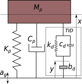
Figure 1. Host structural coupled with a mechanical TID.
Download figure:
Standard image High-resolution imageWhen connecting the electromagnetic transducer, E-TID, to a host structure, as depicted in figure 2, the electromagnetic force reflected back into the mechanical is given by

where (Bl) is the motor constant and I is the current flowing through the motor coil.
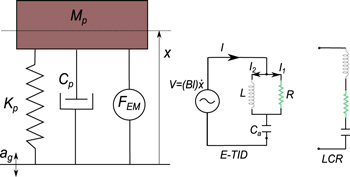
Figure 2. Host structural coupled with a electromagnetic device. Left E-TID structure, right standard LCR circuit.
Download figure:
Standard image High-resolution imageBy considering the electrical circuit, see figure 2, the electromagnetic force reflected back into the mechanical domain may be written as:
where L, Ca and R are the inductance, capacitance and resistance values respectively. By comparing equations (1) and (3) it can be seen that, E-TID and TID are equivalent when:
As discussed in the introduction, recent works [20, 25] have studied the idea of connecting a LCR circuit in series with an electromagnetic device. The LCR series configuration gives the following electromagnetic force
The performance of the LCR series configuration, after optimization, is equivalent to the E-TID at near resonance frequencies but for higher frequencies the E-TID acts as a damper and so reducing the response of higher modes [2]. Note this is the consequence of the E-TID transfer function, FEM, having an additional zero. Figure 3 shows the transfer function  of (i) an E-TID Fd = FEM, see equation (3) (ii) a series LCR Fd = FEM2, see equation (5) and (iii) a damper, exerting a force
  . Figure 3 was generated with L2 = L, Ca2 = Ca, R2 = L/(CaR) providing equivalent performance at resonance for both devices.
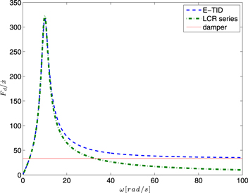
Figure 3. Transfer function  comparison: E-TID, LCR series and damper. Parameters values: Bl = 10 N A−1,
  , Ca = 0.1F, R = 3Ω.
Download figure:
Standard image High-resolution imageThe performance of any absorbing device based on electromagnetic transducers can be compromised by the resistance of the coil. This resistance is inversely proportional to the size of the device [26]. In fact, the non-dimensional coupling parameter (Bl)2/(RcRm), where Rm is the mechanical resistance and Rc is the coil resistance, scales to the device's characteristic length [27]. So small devices, such as the one used in this work, are less efficient, than the those used to control civil engineering structures [27]. The effect of the coil resistance will be discussed in section 4, first we will consider the structure/device combined dynamics.
3. Coupled system equations of motion
The dynamics of the coupled system host structure TID, as depicted in figure 2, when subjected to ground acceleration ag, can be defined by:

where x is the displacement relative to ground. The host structure is defined by its mass Mp and stiffness Kp, structural damping is omitted in this model for simplification, Cp = 0. The amplitude of the relative motion of the mass Mp can be written as:
which is exactly the same transfer function obtained by Den Hartog for the absolute displacement of the main mass when a TMD is connected to it under forcing F = −Mpag, with md mass of the TMD, equal to bd. Note that by considering relative displacement instead of absolute displacement in the TID ground motion problem, the resulting equations are simpler to handle and analytical solutions can be obtained.
According to Den Hartog analysis [1], for a given value of μ, the TMD to host structure mass ratio, the optimal values for natural frequency ratio β, between the absorber ωd and host structure ωp ( ) and TMD damping ratio ζ are

By taking into account the equivalence between TID and E-TID given in equation (4) we obtain the following optimal values for our electronic circuit:
It is important to note than almost any value for resistances and capacitors are commercially available, with the weight and volume of both smaller than their mechanical equivalents. Inductances can be bulky and heavy for bigger values, although as it can be seen in equation (4) the value of L is inversely proportional to kd and by adjusting (Bl) an optimal and light device can be designed.
4. Effect of the coil resistance
The effects of the resistance of the coil, Rc, in series with the E-TID, are shown in figures 4 and 5. Figure 4 shows the evolution of transfer function  as the values of Rc increases. The effects of the losses in the coupled system are shown in figure 5. Both numerical simulations use the parameters gathered in table 1. This figure shows the displacement of the host structure transfer function x/(ag). One strategy to overcome this limitation is to compensate for the voltage drop due to resistance of the coil, this is explained in the next section.

Figure 4. Effect of the resistance of the coil the velocity to force transfer function for the E-TID. Parameters R, Ca and L from table 1.
Download figure:
Standard image High-resolution image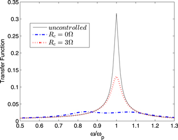
Figure 5. Effect of the resistance of the coil on the performance of the E-TID. Y axis shows the displacement of the host structure x to ground acceleration ag transfer function. Simulation built using all parameters in table 1.
Download figure:
Standard image High-resolution imageTable 1. Parameters using for the simulation in figures 5 and 6.
| μ | (Bl) | Mp | ζp | ωp | Ca | L | R | Rc |
|---|---|---|---|---|---|---|---|---|
| 0.1 | 11 N A−1 | 100Kg | 0.01 | 12.6 rad s−1 | 0.08 F | 0.09 H | 2.9Ω | 3Ω |
4.1. Voltage compensation unit
As mentioned in previous sections, the open-circuit voltage across the terminals of the electromagnetic transducer when driven at a certain velocity  , will be proportional to that velocity. However, when a circuit is closed around the terminals, allowing a current to flow, some of the voltage generated is dropped across the coil resistance and the terminal voltage is no longer simply equal to
  , but at any instant to
  , where I is the circuit current and Rc is the coil resistance. There is also coil inductance, but in this application, where the frequency is of the order of Hertzs, the effects of this can be neglected. The apparent resistance of the coil can be made to approach zero by using IR compensation, a scheme whereby a voltage equal to IRc is added to the terminal voltage. This is achieved by connecting the output of a power amplifier in series with the transducer output, allowing this correction voltage to be added. This scheme is most commonly used for improving the speed regulation of small dc motors [28, 29]. Current flowing through the transducer is measured and converted to a voltage proportional to the current; this is amplified and applied to the input of the power amplifier, see figure 6. If the gain of the amplifier is adjusted such that the voltage added is exactly equal to the voltage drop across the transducer coil, then complete cancellation of the coil resistance is achieved and the voltage applied to the load is exactly proportional to velocity, whatever the current flowing through the coil. In practice, perfect compensation is not achievable, as the system becomes unstable as the gain is increased towards this point. This compensation unit has to be powered, ideally from harvested energy, so the power flow was studied to ensure a self-powered autonomous device can be developed.
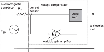
Figure 6. Schematic of the voltage compensator unit connected to the electromagnetic transducer.
Download figure:
Standard image High-resolution image4.2. Study of the power flow.
Power is needed to compensate for the coil resistance. On the other hand the E-TID is able to generate usable power by using a resistance emulator of value R [24]. The ratio of power available to harvest—power needed to compensate from Rc, assuming that both voltage compensation unit and resistance emulator have negligible losses, can be written in the Laplace domain as:
where I1 is the current flowing through the resistive load R and I is the current flowing through the coil. A self-powered device will be possible when the magnitude  , as defined in equation (10), is bigger than unity. The optimal value for R for energy harvesting, so the value of
  is maximum, can be derived by substituting s = jω and differentiating the modulus of
  with respect to R [30]
obtaining that R/L = ω is a maximum for  . On the other hand we have calculated the optimal values for R and L for vibration absorption, see equation (9). Using equation (9), the optimal for vibration absorption R/L coefficient is given by

which is different than the optimal for energy harvesting. Generally we will not be working with optimal parameters for energy harvesting, first (i) the optimal values for R, L and Ca for vibration absorption are estimated and second (ii)  is calculated for the frequency range of interest to ensure
  . A way to study the evolution of the energy parameter
  is to use bode diagrams. As is shown in figure 7,
  is a high pass filter with break frequency equal to R/L. In most applications μ varies from 0.01 to 0.2, so ωp, the host structure natural frequency, is lower than the break frequency R/L, see figure 7.
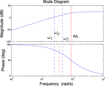
Figure 7. Bode diagram of the energy efficiency indicator  .
.
Download figure:
Standard image High-resolution imageFigure 7 considers a working frequency range ![$[{{\omega }_{1}}\ {{\omega }_{2}}],$](https://content.cld.iop.org/journals/0964-1726/24/5/055015/revision1/sms511266ieqn19.gif) where ω1 = 0.7ωp and ω2 = 1.3ωp. As it can be seen in the figure, the magnitude
where ω1 = 0.7ωp and ω2 = 1.3ωp. As it can be seen in the figure, the magnitude  in the chosen frequency range is above
  , making
  .
.
Substituting the optimal values for R and L given by equation (9), the following inequality must be complied for 
where r = ω/ωp. It can be seen from equation (14) that for a given host structure defined by Kp and Mp, the value of μ is restricted to a maximum due to the losses in the coil Rc.
In order to design an autonomous device, given a host structure and an electromagnetic device, first step is to decide the frequency range of interest. The lower frequency ω1 = r1ωp is substituted in equation (14) to check in the designed device can be self powered. Figure 8 depicts the boundary  , below the boundary the device needs more power that it is able to harvest, above the boundary the device produces more energy than it needs.

Figure 8. Boundary  between self powered devices and devices needing power supply. Using equation (14), the device must be above the boundary for net energy harvesting.
Download figure:
Standard image High-resolution imageFigures 7 and 8 were produced using the data from the experimental set up, detailed in next section, the parameters are summarized in table 2. The square in figure 8 shows the position of the experimental set up in relation with the energy boundary, it is above it, meaning it is possible theoretically to produce more energy than is needed.
Table 2. System parameters for the experiment.
| μ | (Bl) | Mp | ζp | ωp | Ca | L | R | Rc |
|---|---|---|---|---|---|---|---|---|
| 0.13 | 11 N A−1 | 1.6 Kg | 0.01 | 36.11 rad s−1 | 1755 × 10−6 F | 0.5637 H | 50Ω | 3Ω |
5. Experimental testing of an E-TID
The E-TID coupled with host structure was tested experimentally using a technique called real time dynamics substructuring [31]. In this technique the whole system is divided into two substructures: a physical one that will be built and physically tested and a numerical one that will be simulated. In order to replicate the dynamics of the complete system both substructures must be coupled in real-time at the interface between them [32]. A real time strategy consists of the following steps: the numerical model calculates a displacement at the interface due to some external action, this displacement is applied to the physical substructure using a transfer system, in this case an actuator. The force acting of the physical substructure is measured and fed back into the numerical model. This process is repeated until the end of the test. Figure 9 shows an schematic of the substructuring loop: due to ground motion ag each time step the numerical model solves:


Figure 9. Schematic of the substructuring loop.
Download figure:
Standard image High-resolution imageThe current I flowing trough the coil is measured and the force acting at the interface FEM = (Bl)I fed back into the numerical model. The displacement at the interface x is applied to the electromagnetic transducer by an electromechanic actuator.
The chosen electromagnetic transducer is a moving magnet DC voice coil linear actuator manufactured by H2W technologies. Due to the small scale of the device, high losses due to Rc are expected and so our experiments are focused on small scale host structures and vibration absorbers. The motor parameters are Bl = 11N/A and Rc = 3Ω.
In order to establish the required circuit current at a low operating frequency and low voltage, high values of capacitance, of the order of thousands of micro-Farads are required. Widely available electrolytic capacitors were used, since they are polarized they have to be supplied through a rectifier. A conventional diode rectifier cannot be used as it does not allow bi-directional energy flow, therefore a synchronous rectifier that uses MOSFET switches to replace the diodes, was used. The inductance was provided by a Ferranti moving-coil regulator and generalized transformer unit. This is a variable three-phase transformer which, although not designed primarily for this purpose, has the convenience of coil tapping points brought out to front-panel terminals. Interconnections between these terminals allowed the required inductance to be obtained, together with acceptably low losses.
A voltage compensation unit, as described in section 4.1 was used to compensate for the voice coil internal resistance. The residual resistance, necessary to ensure stability, was chosen to be Rr = 0.8Ω. Table 2 gathers the parameters for one of the tests. Circuitry parameters fulfil equation (14), so the device can be classified as self powered. For the given host structure Mp, Cp, Kp and considering our device Bl and Rc, μ was chosen so the equation (14) is fulfilled. From μ all the circuitry parameters: R, L, Ca are derived from Den Hartog optimization [1], according to equation (9).
We now discuss the experimental results. As already mentioned, the initial resistive load of 50Ω was derived from Den Hartog [1]. Results for this value, compared with uncontrolled host structure, are shown in figure 10 panel(a). This panel also shows the experimental results being in close agreement with an ideal numerical TID, defined by bd, kd and cd, derived from Ca, L and R with equation (3). The R value was adjusted to improve the performance, since there are some losses in the circuit due to the residual resistance after voltage compensation, Rr, the system is slightly over damped and usually the optimal resistance R will be higher than the one predicted for an ideal system. Note than since we are using a resistance emulator, as long as we are able to generate power, the values of the resistance presented R can be changed in real time. Figure 10(b) shows that Den Hartog's fixed points are not exactly at the same level for the experimental system, however these could be regulated by adjusting β via L. or Ca. Panel (b) represents the displacement of the host structure for different values of R. The device can present always the same R or a frequency dependant R control law can be derived so the displacement of the host structure is minimized. The frequency of excitation can be derived at a minimal energy cost by monitoring the zero crossings of the rectification unit.
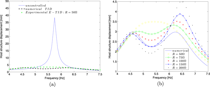
Figure 10. Host structure displacement, ground acceleration  . (a) Uncontrolled and with an E-TID connected with R = 50Ω. (b) Response for different values of R.
Download figure:
Standard image High-resolution imageFigure 11 depicts the estimation of the power used for voltage compensation and that available to harvest accros the resistance emulator, for the different tested values for R. Power was estimated by measuring I and I1 and calculating I12R and I2Rc. This estimation does not include the losses in both the compensation unit and in the resistance emulator.Efficiency in the voltage compensation unit can be over 90% if using class D switching amplifiers, [33, 34]. Efficiency in the resistance emulated was tested in previous works and estimated at 85–90% [24]. As it is shown in figure 11, the device crosses the self-powered capability boundary for R = 75Ω, at the lower frequency limit of 4 Hz, corresponding to r = 0.7.
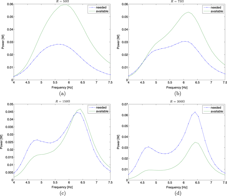
Figure 11. Power needed by the voltage compensation unit and available to harvest trough the resistance emulator for different R values (a) R = 50Ω, (b) R = 75Ω, (c) R = 150Ω and (d) R = 300Ω.
Download figure:
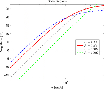
Standard image High-resolution imageThe R value that crosses the boundary can be estimated analitycally by plotting the bode diagram of  for the different R values under consideration, using our experiments parameters. Figure 12 shows the bode diagrams of the energy index
  for the tested values for R, in order to check that the magnitude of the energy
  is above
  . Vertical dashed lines represent the lower and upper limits of the frequency range of interest corresponding to r = 0.7 and r = 1.3. It shows how the lower boundary r = 0.7 crosses 0 dB (corresponding to the self powered boundary) when R = 75Ω as it was found experimentally.
Figure 12. Bode diagram for the energy index ratio for the different experimental R values. R = 75Ω crosses the self powered capability boundary.
Download figure:
Standard image High-resolution image
6. Conclusion
In this paper we proposed the synthesis of a tuned inerter damper with an electromagnetic transducer and an electronics circuit. The proposed device is easy to implement and very versatile. The optimal values of the circuitry are derived following the classical theory of Den Hartog [1]. A voltage compensation unit was developed in order to avoid that the losses from the coil affect the performance of the device. With a power balance study the E-TID parameters range of values for energy efficient devices were derived. Energy recovery from the vibration absorbed together with variable damping was possible through the use of a resistance emulator instead of a passive resistance R [24]. All numerical findings were experimentally tested. A substructuring test rig was designed: the E-TID was physically built and the host structure was emulated numerically. Due to the small scale of the motor used, in order to present a energy efficient device, the mechanical equivalent inertance of the device, bd is small. This limitation will not be a problem for bigger devices [27]. The experimental results are very promising, the E-TID, the tested configuration was successful in terms of vibrations absorption, with results close to an ideal mechanical TID and in terms of energy, since it was able to harvest more energy that it was needed. In particular we were able to harvest in the order tens of milliwatts, about 2/3 of the power was required to compensate for the losses in the coil. The unused power can be stored and/or can be used instanlty in control and monitoring schemes. One significant advantage of working in the electrical domain is the possibility of easily connecting elements in parallel to achieve multi-frequency vibration absorbers, this will be the matter of future work.
Acknowledgments
AGB is supported by EPSRC grant EP/J008532/1. SAN is supported by an EPSRC fellowship grant EP/K005375/1.