
Abstract
The advanced gravitational wave interferometers are reaching unprecedented levels of strain sensitivity, that is, of accessible volume of Universe, in search for the most elusive cosmic sources. In this effort, the optical design of these detectors places increasingly stringent requirements on the components. Thermal effects, related to the fraction of laser beam power absorbed in the optics, and deviation of components from specifications, intrinsic to the state of art of the production processes, need to be addressed to recover the ideal operation of the detector. Ring heaters (RHs) are thermally coupled actuators conceived to precisely tune the radius of curvature (RoC) of the highly reflective surface of mirrors. The actuator concept has been improved and properly rescaled to design dedicated heaters for different mirrors of the Advanced Virgo detector (namely test masses, power and signal recycling mirrors, filter cavity mirrors). This paper describes the design features and performances of the RHs installed around the test masses of Advanced Virgo, highlighting the improvements of this design with respect to previous actuators. In this case, the dynamic actuation range reaches 100 m over a static RoC value of 1500 m, with the deformation largely dominated by the spherical component. The obtained actuation gain is  = − 0.93 m W−1, with a typical settling time of about 6 h.
Export citation and abstract BibTeX RIS

Original content from this work may be used under the terms of the Creative Commons Attribution 4.0 license. Any further distribution of this work must maintain attribution to the author(s) and the title of the work, journal citation and DOI.
1. Introduction
The reach of extremely sensitive detectors based on optical transducers is intrinsically limited by deviations of optics from ideal operation. The design of the optical layout is usually based on the assumption that all components are perfectly modeled by flawless optics, then requirements are imposed on the real system components so that deviations from ideality still allow correct operation at the target sensitivity. However, requirements could eventually become unfeasible, as inherently due to production processes, technological limits or operating conditions. In all these cases, the only way to recover an almost ideal behavior is to design a complementary system to actively compensate for relevant deviations. Thus, in this sense, the optical transducer plus its complementary compensation system equal a prefect device.
An emblematic case in this class is represented by gravitational wave (henceforth, GW) interferometric detectors, that exploit the Michelson's scheme with km-long arms to reveal extremely small geodesic deviations induced by GW. In an advanced GW detector [1–3], the gain of the optical transducer is further enhanced by using resonant optical cavities in the interferometer arms and by adding resonant cavities at the input or output port (power recycling cavity, PRC, and signal recycling cavity, SRC). Since they must precisely match the laser beam mode geometry and maintain the resonance condition, resonant cavities place severe technical requirements. Whether and where these requirements are more stringent depends on the specific optical design of the detector.
When considered in terms of production processes, requirements on core optics of nowadays GW detectors are too tight to be met by state-of-the-art manufacturing techniques. The actual mirror surface radius of curvature (RoC) needs to be actively tuned to approach the perfect operation of the interferometer.
Besides, even for a perfect mirror, the RoC is affected by the thermal status of the interferometer at full power. The increase of the input laser power [4] aimed at reducing the shot noise limit, together with a finite (below 1 ppm [5]) optical absorption in the mirror coatings, eventually causes thermal effects that bring the system away from the ideal behavior. These effects are particularly relevant in the optics belonging to the arm cavities, where the high optical gain implies very high power impinging on mirrors, of the order of 105 W. Heat deposited at the mirror surface causes the thermo-elastic deformation of the mirror body, changing its RoC.
In all these cases, to recover the optimal surface figure of mirrors, the RoC can be acted upon using a dedicated ring heater (RH) placed around their lateral surface [6–9] (see the scheme in figure 1). The RH is radiatively coupled to the mirror in order to induce a compensating thermo-elastic deformation of proper magnitude. This effect is also exploited to correct surface figure errors due to the manufacturing process.
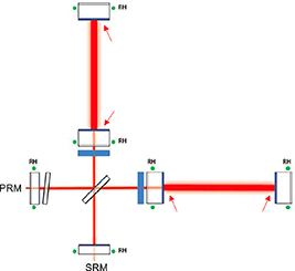
Figure 1. Advanced Virgo layout. RHs installed with the main goal to correct the RoCs imperfections due to fabrication errors or power absorptions are represented by the green dots. The arrows show the mirror surfaces where the thermal effects are more relevant due to the high power circulating in the FP cavity [4]. The labels PRM and SRM are referred to the power and signal recycling mirrors respectively.
Download figure:
Standard image High-resolution imageThe action of the RH produces, besides the thermo-elastic dilation, an additional change of the optical path in the mirror bulk due to thermo-optic coupling 6 , resulting in a spurious thermal lens. As from the optical layout, the volume of the arm cavity input mirrors lays within the PRC with the high reflectivity (HR) surface facing the arm. Therefore, the lens caused by the RH action affects the PRC behavior. The latter feature can be exploited to get additional benefits. The RH can provide a limited correction of the thermal lens induced by the power absorption from the circulating laser, that also affects the PRC. Furthermore, the possibility to use the RHs to tune the mechanical normal mode frequencies of the mirrors away from cavity parametric instabilities has been highlighted [10, 11]. As final item in this not exhaustive list, a fine adjustment of the cavity reflectance is possible by tuning the etalon effect in the mirror bulk [12].
The design requirements of RHs are driven by the objective of recovering the design mirror RoC, correcting for manufacturing errors and surface thermo-elastic deformation so that the interferometer can be operated at full sensitivity. To this aim, the Advanced Virgo RHs must:
- provide a correction of the HR surface of the arm cavity core optics (also called test masses, TMs) with the required dynamics and precision. With a foreseen intracavity maximum power of the order of 1 MW and a coating absorption of a fraction of ppm, the expected maximum thermo-elastic change of the TM RoC reaches up to 50 m over a static value of the RoC of 1.5 km. As a safety margin, the full dynamical range of correction must reach twice this value (100 m), with a precision of ±2 m [4];
- provide a correction for the RoC of mirrors in the PRC and SRC, with a precision of ±8 m [4];
- the applied correction must be highly spherical (see further, section 3). The same requirement is also desirable for the thermal lens induced in the mirror volume, especially in the case of Advanced Virgo whose optical design includes a marginally stable PRC at the input port [1].
The integration of the RH in the interferometer places additional requirements:
- it has to be compatible with high temperature operation under vacuum;
- it must radiate mainly toward the optic and minimize the interaction with the surrounding environment;
- the coupled noise sources must be compliant with the Advanced Virgo sensitivity curve. In particular, a factor of ten below the design strain sensitivity (
 between 100 Hz and 500 Hz [13]) is requested as safety margin for spurious noise.

In this paper we focus on describing the design features of the RH installed around the Advanced Virgo TMs since they must fulfill the most stringent requirements. The RHs installed around the PRM and SRM are designed following the same concept. The improved performances of the present design with respect to previous actuators are also presented.
2. Design of the RH
The working principle of the actuator consists in the contact-less tuning of the RoC provided by heating elements radiatively coupled to the mirror. Due to the small value of the thermal conductivity in silica mirrors ( 1.4 W mK−1), the induced temperature gradient is localized so that the resulting thermo-elastic deformation is dominated by bending over bulk dilation, eventually providing a change of the RoC of the mirror surface.
The Advanced Virgo RH consists of two co-axial, thin o-rings made of borosilicate glass (pyrex), that encircle the mirror. Pyrex is neatly vacuum compatible, while its high surface emissivity ( ) guarantees an efficient radiation coupling with limited temperature increase. Each ring is powered by Joule heating through a Nickel Chrome (NiCr 80%/20%) conductive wire tightly wrapped in helical coils around it, then acting as a radiator. The total resistance of the wire is 50 Ω. To ensure a good thermal contact, the wire has a rectangular cross section, 1 mm wide and 0.1 mm thick. While the glass provides an electrically insulating support to the wire, the coil pitch must be large enough to avoid the risk of short-circuiting adjacent turns. The length of wrapped wire is set by the requirement on the dynamical range, once current limits due to integration constraints are taken into account.
Using two radiators instead of one allows to optimize the RH thermalization time. Indeed, compared to a single ring, a couple of radiating rings allows the thermal time to be reduced without any increase in the working temperature.
Furthermore, if the wires are assembled in counter flux configuration, the arrangement with two rings has the relevant advantage of reducing the RH stray magnetic field gradient (see section 4).
The relative amount of power radiated by the rings that strikes the mirror lateral surface is practically limited to 0.5 (in fact, always less than that). To increase the efficiency of the system, the heat that radiates away is gathered and conveyed toward the mirror by a copper shield enclosing the rings, that in addition provides a stable and protective support for holding the rings around the TM. The shield has a c-shaped rectangular cross section and it is internally polished to enhance its reflectivity. The radiators are kept centered inside the shield by three equally spaced, dovetail-shaped MACOR supports, blocked to the inner copper surface (see figure 2).
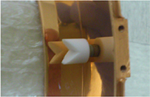
Figure 2. Dovetail-shaped MACOR supports to hold in place the rings inside the shield.
Download figure:
Standard image High-resolution imageThe supports of one ring are shifted by 60∘ with respect to those of the other ring, to reduce the overall impact on the angular uniformity of the emitted pattern. Figure 3 offers a schematic view of the RH accompanied by relevant quotes.
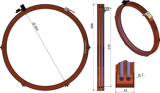
Figure 3. Schematic view of the RH size and components. The scheme provides different views of the actuator, together with some relevant geometrical quotes in mm. The holders hosting the wire connectors are colored in black and gray.
Download figure:
Standard image High-resolution image3. Characterization of the actuator
A full scale prototype of the Advanced Virgo RH for the TM has been built, assembled and operated in high vacuum (10−6 mbar) to allow testing of its behavior, such as thermal transients and angular uniformity of radiation. Heating-cooling cycles in vacuum have been repeated in order to assess the relevance of aging effects. No evidence of modification in the structure or efficiency have been observed during these tests.
Heating up tests have been performed providing 24 W to each ring, close to the maximum expected operating power, corresponding to a change in RoC of about 50 m. The temperatures of one of the rings and of the shield have been tracked up to the regime conditions using PT100 sensors. The resulting experimental curves are shown in figure 4. The temperature of the ring versus time is fitted by the sum of two exponential functions characterized by two different time constants  min and
  min. τ1 is interpreted as the intrinsic time constant of the pyrex ring, being similar to the heating time of the ring alone
  min. Due to the coupling with the copper shield, the temperature fit requires an additional exponential with a longer time constant τ2.
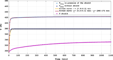
Figure 4. Measured thermal behavior of the pyrex ring with (blue open circles) and without (blue dots) the shield, applying  = 48 W. The shield temperature is also shown (magenta dots), together with exponential fits to the measurements.
Download figure:
Standard image High-resolution imageThe angular uniformity of the RH thermal radiation was measured in vacuum by means of an IR photodiode with a wide angular acceptance (36∘). The photodiode has been clamped to a rotary stage, in order to stay at a distance of 8 mm from the inner surface of the rings. The measured signal, proportional to the radiated power, is shown as a function of azimuthal angle in figure 5. The fluctuations of the recorded signal lay within 10% of the average value.
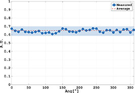
Figure 5. Angular uniformity of emitted radiation measured on an Advanced Virgo RH.
Download figure:
Standard image High-resolution imageThe optical simulation tool Zemax has been used to obtain the spatial distribution of the radiated heat impinging on the mirror surface. The resulting power density is shown in figure 6 as a function of the position along the Zemax detector corresponding to the lateral mirror surface. The profile is adequately fitted by a Gaussian function with FWHM  0.07 cm.
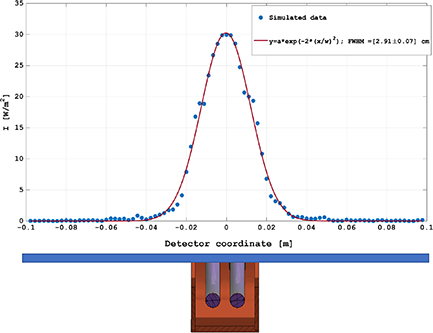
Figure 6. Intensity profile of the power absorbed on the mirror lateral surface simulated using Zemax, with total absorbed power is 1 W. The schematics below the plot show the position of the Zemax virtual detector with respect to the RH. The red solid curve is the Gaussian fit to data.
Download figure:
Standard image High-resolution imageIn order to study the optimal position of the RH plane along the mirror axis, we define an actuation gain  as the differential change in the RoC of the HR surface per unit power dissipated in the coils. The latter can be computed using a finite element analysis (FEA) simulation in which the described features of the RH are included, namely its intensity profile, shield absorption and geometrical dimensions. The assumed RH model parameters are defined in section 4, table 1. The simulation provides, for a set of values of the power fed to the actuator, the structural displacement of the mirror surface from which the corresponding RoCs are evaluated. The value of the actuation gain is computed as the derivative of the RoC variation versus total RH power, at the nominal (cold) mirror condition. It is worth noting that, since the RH can only heat the mirror edges, its action always decreases the RoC of the mirror with respect to its cold value. The outcome of this process for various positions of the RH is shown in figure 7, where the distance between the RH median plane and the HR surface is reported in abscissa. As the RH approaches the anti-reflective face of the mirror, a more and more relevant part of the radiated power falls out of the mirror edge, causing a progressive reduction of the gain. As a consequence, there exists a maximum of the actuator efficiency corresponding to a specific RH position close to the anti-reflective mirror side. In the following, we always suppose the RH placed at this optimal point. It is worth to notice that in this condition the effect of the actuator on the anti-reflective surface RoC is negligible (
 is about 3% of the gain at the HR surface).

Figure 7. The quantity  at different distances from the HR surface. The mirror thickness is 20 cm.
Download figure:
Standard image High-resolution imageTable 1. Input parameters used for the RH FEA simulations presented in this paper [16]. All parameters except power loss coefficient and emissivity are referred to silica mirrors.
| Symbol | Value | Description |
|---|---|---|
| κ (W m−1 K−1) | 1.38 | Thermal conductivity |
| α (K−1) | 5.4×10⁻⁷ | Thermal expansion coefficient |
| n | 1.452 | Index of refraction |
 (K−1) (K−1) | 1×10⁻⁵ | Thermo-optic coefficient |
| ρ (kg m−3) | 2203 | Mass density |
| Y (GPa) | 73.2 | Young's modulus |
| σ | 0.164 | Poisson's ratio |
| c (J kg−1 K−1) | 732 | Specific heat |

| 18% | power loss coefficient |
| ε | 0.9 | Emissivity of pyrex |
The dependency of the RH efficiency on the geometry of the shield and rings has been investigated using optical and FEA simulations. Both parabolic and rectangular profile shields have been considered and no relevant difference in the actuation gain was observed. Thus, further simulations have been carried out using a rectangular profile and extensively changing its geometrical parameters, distance from the mirror surface, cross section of rings (circular vs rectangular). Within the investigated configuration space, the obtained RH dynamics showed to be negligibly affected by changes in geometry. A detailed description of the carried tests and of the results can be found in [4].
FEA simulations also allow the deviation of the mirror surface from an ideal sphere to be quantified. We define the HR surface sphericity as:

where  stands for the root-mean-squaref value (RMS) of the purely spherical contribution to the surface profile, while
  is the RMS of the residual profile once the spherical component is removed.
  can be used to quantify the relevance of the non-spherical part of the thermo-elastic actuation provided by the RH. In a fully analogous way, we can define the sphericity of a static lens due to distortion in the mirror bulk as:

where the RMSs are evaluated on the induced wavefront distortion. Again,  can be used to quantify the relevance of the non-spherical part of the thermal (diverging) lens arising from the sum of thermo-optic and thermo-elastic effects inside the mirror, when the RH is active. A full thermal/structural simulation of an Advanced Virgo cavity mirror acted upon by the RH has been used to obtain the steady-state thermo-elastic deformation. Then, the spherical contribution was obtained by performing a Zernike polynomial decomposition. Finally,
  was evaluated to be
  and
and  , that means the spherical contributions to surface deformation and thermal lens are largely dominant.
Furthermore, simulation tools that deal with the optical behavior of the interferometer can be also exploited. A widely used parameter to quantify the impact of deviation from ideal conditions in the PRC is the control sideband cavity gain [14]. Since the PRC is marginally stable, the cavity gain is particularly relevant in the case of Advanced Virgo. Usually, requirements are derived assuming a maximum tolerable decrease of the gain by 5% from its ideal value. We used these simulations to assess the effect of uncertainties in position/tilt angle of the RH with respect to the mirror, and of temperature drops in the emitting rings due to the presence of the MACOR supports. In both cases, estimation of the thermal lensing in the input TM is derived using FEA and passed to the optical simulation tool FOG [15], that computes the PRC gain in power-recycled configuration. The contribution from the thermo-elastic deformation of the HR surface was not considered since it does not sensibly affect the beam in the PRC.
Misalignments of the RH are grouped in two classes: tilt angle of the RH plane with respect to the TM cross section and parallel translation of the RH center with respect to the TM center. Plots reporting the estimated drop of the PRC gain versus the amount of translation and versus the tilt angle for a RH at full nominal power are shown in figure 8. Requirements on maximum allowed mis-centering ( mm) and tilt (
 ) are derived by limiting the PRC gain drop to 5%.
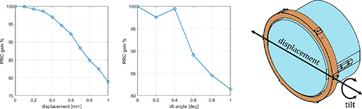
Figure 8. Drop of the PRC gain as a function of RH displacement (left plot) and tilt (right plot). Displacement and tilt are defined according to the arrows in the schematic on the right.
Download figure:
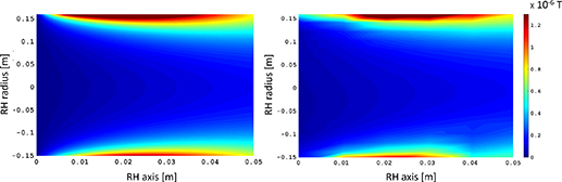
Standard image High-resolution imageAs described in section 2, each RH pyrex ring is kept in position by three MACOR supports. The supports of the two rings can be arranged in different relative configurations. We consider here two extremal cases, with supports in coincident positions or shifted by 60∘. The temperature distribution in the rings for the two choices has been obtained with an FEA at full nominal power. The corresponding optical path length deformations in the TM, with respect to a perfectly uniform RH, are presented in figure 9 as maps on the whole mirror. The simulated PRC gain loss is 5% for coincident supports and 1.2% for shifted supports. The latter values explain the choice made for the design, as described in section 2.

Figure 9. Sketch of temperature distribution in the pyrex rings and map of optical path length difference with respect to uniform heating for coincident MACOR supports (left) and shifted supports (right).
Download figure:
Standard image High-resolution image4. Actuation performances
The Advanced Virgo RH performances in nominal conditions can be estimated via FEA. The action of the RH is conveniently and exhaustively divided in the two co-present effects, namely the thermo-elastic deformation of the HR surface, that is quantified by the resulting spherical RoC, and the onset of bulk thermal (diverging) lens, quantified by the spherical dioptric power. Both effects have been evaluated with transient and steady state simulations, in order to provide associated time constants and dynamical ranges. FEA simulations require a set of model input parameters (see table 1). Physical mirror parameters are set to available literature values. Besides, a fundamental value is the coefficient of power loss  that measures the fraction of input power that is lost due to shield radiation or conduction toward environment. This coefficient, expressed as a percentage of the input power, depends on poorly known variables such as the effective shield emissivity and the conductance coupling with clamping structure.
In order to constrain the power loss coefficient, the behavior of the thermal lens associated to the RH actuation has been experimentally studied on real mirrors. Hartmann wavefront sensors (HWS) [17, 18] installed in Advanced Virgo can record maps of the thermal lens induced by the RH in the input mirrors of the two arms, by measuring the wavefront distortion of probe beams injected in the interferometer from the main beam injection and detection ports. These maps are analyzed using a Zernike polynomial decomposition to give the evolution of the dioptric power of the thermal lens in time. The actual dioptric power on the mirror is obtained by rescaling the HWS measurement by the magnification of the imaging telescopes.
The measured thermal lens response to an RH actuation on the input mirror of the Advanced Virgo West arm, using a total step input power  15 W, is shown in figure 10 [19]. The uncertainty in the optical magnification (
 , computed assuming a conservative error in the position of optics along the HWS beam path of 1 cm) is taken into account by the shaded area. The graph shows a prominent overshoot: the lens achieves a maximum absolute amplitude before turning back to reach the steady state. This expected feature is related to the slow heat diffusion towards the center of the optics, caused by the small thermal conductivity in silica.
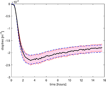
Figure 10. Plot of the transient thermal lens response in dioptres as measured on West arm input mirror with a total RH power of 15 W (solid black line). Shaded area corresponds to the uncertainty in HWS probe beam magnification. Dashed curves are the FEA simulations fitted with respect to the power loss  and
and  .
.
Download figure:
Standard image High-resolution imageA fit of the simulated response to the experimental curves related to the extremal optical magnification values gives for the power loss the values  . Then, the power loss coefficient
  is obtained as an average of the
  . Figure 10 also compares the measured response with the curves simulated using the fitted power losses. The curve of the simulated thermo-elastic response to a RH step input power (15 W), based on the fitted
  , is shown in figure 11.
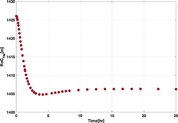
Figure 11. Plot of the simulated transient thermo-elastic deformation in RoC for a total RH power of 15 W.
Download figure:
Standard image High-resolution imageFigure 12 presents the TM steady state, in terms of the change in RoC and dioptric power respectively, as a function of the continuous power dissipated in the coils. According to the plots, the requirement on the dynamical range of RoC actuation set in section 1 is fulfilled by applying up to  W per coil.

Figure 12. (Left) Strength of the thermo-elastic effect on the HR surface as a function of the power dissipated in the coils (dots). The linear fit is also shown (solid line). (Right) Strength of the thermal lens inside the mirror as a function of the power dissipated in the coils (dots). The linear fit is also shown (solid line).
Download figure:
Standard image High-resolution image5. Noise couplings
Stationary fluctuations of the voltage driving the RH coils might add noise in the interferometer sensitivity band through several mechanisms.
The noise induced in the TMs via heat deposition is due to the fluctuating emitted power. Being the absorbed heat concentrated on the mirror lateral surface, direct thermo-elastic and thermorefractive couplings to the optical path in the TM may be ignored. In fact, the penetration of thermal fluctuations is limited to only about 35 µm in silica [20]. Similarly, effects related to the radiation pressure average to zero since the RH is placed symmetrically around the TM. Since almost all the radiation emitted by the RH impinges normally to the lateral surface of the mirror, the radiation pressure contribution due to the positioning of the RH towards the AR-surface is negligible.
Phase noise is introduced by flexure noise that couples the overall power fluctuations to displacements of the HR surface of the mirror. The displacement can be seen as the consequence of the bending under the action of the RH, when the center of mass of the mirror is at rest. However, power swing is passively smoothed by the RH thermal inertia, thus making easier to meet the requirements on spurious noise. As a result, the limit placed by the requirements on power fluctuations is in the range of few mV  [21].
[21].
The stray magnetic field due to the current in the coils can couple to mirror motion through the magnetic force acting on the four small magnets glued to the TM face for steering purposes. The introduced displacement along the optical axis z translates in the strain equivalent noise [22]:

where µ is the magnetic momentum of the magnets, f is the frequency, M is the mirror mass, L is the arm length of the interferometer and  is the component of the stray field along the optical axis z. The gradient
  is computed at the nominal position of magnets, for 1 A current in the coils. Being the small magnets arranged in quadrupole configuration, the spurious magnetic forces on the mirror would be perfectly balanced for a perfectly symmetrical system. However, to take into account the residual imbalance of the magnetic forces, a parameter
  is introduced [23]. In the Advanced Virgo RH, the configuration of the coils in counter flux helps in reducing the amplitude of the magnetic field gradient. The limit placed by the noise requirements on the current power spectrum is obtained by plugging in equation (3) the parameters valid for the Advanced Virgo TMs. The value of the field component Bz
was obtained both by numerical computations and by direct measurement on a RH prototype. The estimates provided by the two methods are in full agreement (see figure 13). Assuming a center band frequency
is introduced [23]. In the Advanced Virgo RH, the configuration of the coils in counter flux helps in reducing the amplitude of the magnetic field gradient. The limit placed by the noise requirements on the current power spectrum is obtained by plugging in equation (3) the parameters valid for the Advanced Virgo TMs. The value of the field component Bz
was obtained both by numerical computations and by direct measurement on a RH prototype. The estimates provided by the two methods are in full agreement (see figure 13). Assuming a center band frequency  100 Hz yields the requirement on the current power spectrum
  (@100 Hz)
  for an RH at full power. The contributions to strain noise from magnetic torques is negligible.
Figure 13. Maps of the Bz component of the stray magnetic field in the proximity of the RH, normalized for 1 A current in the coils. Left: estimate provided by numerical computations. Right: measurement done on RH prototype using a Fluxgate probe, on points spaced by about 2 cm. The image rendering interpolates the data to a bidimensional surface.
Download figure:
Standard image High-resolution image
The RH is essentially a wire with a voltage gradient held in proximity to the TM. Therefore, it will exert an electrostatic force on the TM. If the voltage is fluctuating, then the electrostatic force will fluctuate as well and inject displacement noise into the interferometer. The electrostatic force can be exerted along the longitudinal or transversal directions or as a torque. Computations in [21] show that the most stringent requirement comes from the longitudinal component. Following [22], the longitudinal noise assumes the form:

where  is the voltage drop applied to the RH coils and
  N V−2 is a conversion factor obtained by finite element modeling [21]. The resulting requirement on the voltage power spectrum can be obtained assuming a maximum voltage drop of 30 V [22], yielding
  (@100 Hz)
  mV
mV .
.
6. Conclusions
In this paper we have presented the actuator (RH) installed for the tuning of the RoC of the arm mirrors in Advanced Virgo. The design of the RH has been shown to meet the operational requirements in terms of actuation range and precision, being also compliant with the integration in the detector in terms of vacuum compatibility and injected spurious noise. We collected here reference curves for the calibration of the actuation strength of thermal lensing and thermo-elastic deformation in the test masses. The estimated actuation gain for the RoC change is −0.93 m W−1. Similarly, the thermal lensing gain is 7.8 10−6 m−1 W−1. Both the effects are largely dominated by their spherical components. The RH guarantees a full dynamical range of RoC correction up to 100 m over 1.5 km, approaching the steady state curvature to better than 5% in about 6 h. The estimates done for the thermal lens in the input mirrors of the interferometer were tested against experimental data collected in working conditions and validated. Finally, the inclusion of RH misalignment effects in the optical simulation of the whole detector allowed the maximum acceptable tilt (± 0.5∘) and displacement (±0.5 mm) with respect to the test mass to be obtained.
The described RH is part of the thermal compensation system (TCS) of Advanced Virgo. The end-TM RHs have been used in the Advanced Virgo O3 observation run to compensate for the optical losses in the FP cavities. The actuator power tuning allowed for an increase of about 15% of the intra-cavity power and a decrease by a factor of two of the power at the output port of the interferometer. A detailed description of the use of the RHs in Advanced Virgo and their results will be the subject of an upcoming article dedicated to the TCS system.
Acknowledgment
We are indebted to the Virgo Collaboration for allowing us to use the data collected during the measurements reported here, and are grateful for support provided by the Virgo Collaboration and the European Gravitational Observatory during these tests. The authors thank R Simonetti, M Perciballi and A Bazzichi for their precious technical assistance. This work was promoted by the Virgo Collaboration and supported by INFN Roma Tor Vergata and University of Roma Tor Vergata.
Data availability statement
All data that support the findings of this study are included within the article (and any supplementary files).
Footnotes
- 6
A further effect, due to elasto-optic coupling, is normally negligible in mirrors made of high grade fused silica.