

Abstract
Wide-range humidity sensing and monitoring applications including instrumentation, agriculture, meteorology, biomedicine, and food processing have attracted long-standing interests, where recently substantial progress is made in both sensing-material science and microfabrication technologies to achieve portable, reliable and low-cost humidity sensing instruments. Due to their high sensitivity, enormous miniaturization potential, and well-developed high-volume microfabrication technologies, microelectromechanical systems (MEMS)-based piezoresistive cantilever devices covered by large-surface-area nanostructures of hygroscopic materials offer an ideal platform for highly sensitive humidity detection.
Since resonant gravimetric sensing is the dominant humidity sensing technique in recent research works, in this paper, resonant actuation principles for microcantilevers (i.e. the dynamic operation mode) are addressed and compared with respect to the quality of the amplitude and phase signals, as required for on-line frequency tracking using a phase-locked loop circuit. Parasitic feedthrough effects are considered between the resonance-mode (f 0) excitation element and the piezoresistive detection circuit, which can lead to a reduction of stop-band attenuation, the generation of a parallel resonance in close vicinity of f 0, a hardly detectable 90° phase jump, and a long-term drift of resonance frequency and phase shift. Methods for eliminating these parasitic feedthrough effects have been considered, including de-embedding of the motional signal by later data processing and the integration of a reference cantilever or circuit.
Then, different concepts of environmental sensing using microcantilevers are described, including detection of particulate matter and gas molecules/volatile organic compounds. Depending on the condition of the cantilever during sensing operation, two different modes have been used to sense the target analyte (i.e. static and dynamic modes). In a static operation mode, mass change of the cantilever, surface stress, or swelling of a layer on top related to the uptake and binding of particles or molecules on the cantilever are detectable via a deformation of the cantilever (i.e. by deflection or strain), which can be sensed by an integrated piezoresistive strain gauge. Quasistatic bending of the cantilever as well as frequency down-shift of an excited resonance mode are normally used for detection.
Humidity adsorption/desorption characteristics of such piezoresistive microcantilevers can be modified using hygroscopic layered materials deposited on the cantilever, among which we address metal oxides, ceramics, organics, or organic/inorganic composites. These thin layers comprise preferentially concave or convex nanostructures (e.g. pores, particles, colloids, rods, or fins), which provide a sensing surface of large surface-to-volume ratio and thus a large number of binding sites for highly efficient adhesion of water molecules.
Finally, fabrication processes of integrated piezoresistive microcantilever-based humidity sensors, including micromachining/MEMS technology, integration of nanostructures and their combination with deposited hydrophilic materials are described. Lastly, their humidity sensing performance is compared with competing state-of-the art and advanced MEMS devices, e.g. capacitive micromachined ultrasonic transducers, quartz crystal microbalance, thin-film bulk acoustic resonator, surface acoustic wave resonator and complementary metal oxide semiconductor-MEMS for gravimetric sensing with respect to, e.g. sensitivity, hysteresis, and response time.
Export citation and abstract BibTeX RIS
1. Introduction
1.1. Humidity sensing
Humidity sensing is the detection of water molecules in the environment. Based on different measurements techniques, humidity parameters are defined in diverse ways, including relative humidity (RH), dew/frost point (D/F PT) and parts per million (by weight: PPMw and by volume: PPMv), in which the two latter are the subclasses of absolute humidity (AH) [1–3]. AH is the mass of water vapour in a unit volume of air, which is specified in grams per cubic meters (g/m3); while RH is the ratio of the partial pressure of water (p w) present in a gas to the saturation vapour pressure (p ws) of the gas at a certain temperature, which simply represents the ratio of the amount of water vapour present in the atmosphere to the maximum amount the atmosphere can hold [4]. p ws is related to the temperature of air, thus RH is a temperature dependent parameter, and is usually expressed as percentage.
According to the measurement units, humidity sensing is divided into two types, i.e. RH sensing and AH (moisture) sensing. AH sensing (D/F PT, PPMw and PPMv) describes the absolute amount of water molecules in the air environment, and although this measurement is more difficult to conceive, it has extensive applications in industry used for traceable purpose (trace moisture measurement) as primary sensor. Compared to AH sensing, RH sensing is much simpler and cheaper, in which it is most commonly used in applications involving indoor air qualities, processing control, and research laboratories [5–7]. Therefore, in the majority of humidity measurement applications, RH sensing is more preferable than AH sensing.
The recent achievements in technologies have led to the miniaturization of humidity sensors, especially the development of silicon microtechnology, which offers great advantages with respect to batch fabrication and reduction of cost. In the past decades, numerous types of RH sensors have been designed and fabricated. However, it has to be emphasized, that it is not a simple matter to develop sensor which units in itself the complete a set of favourable characteristics: (1) good sensitivity over a wide range of both humidity and temperature; (2) short response time; (3) good stability and reproducibility; (4) small hysteresis; (5) good durability and long lifetime; (6) negligible temperature dependence; (7) easy fabrication and low cost; and (8) resistance to containments and so on [8–12].
Although various kinds of humidity sensors have been reported in the last years, in which micromachined humidity sensors were normally classified based on their sensing principles (e.g. resistive humidity sensors, capacitive humidity sensors, and piezoeresistive humidity sensors), a comprehensive review focusing on piezoresistive microcantilever-based humidity sensors, to the best of our knowledge, has not been available in literature. According to the classification presented by Huang and Huang [1], piezoresistive sensor is one of the generally utilized and commercially available, yet promising, sensors for measuring the humidity level. Meanwhile, in terms of resistive sensing mechanism, the humidity sensor can be divided into normal resistive humidity sensor and piezoresistive humidity sensor, which measure a change in conductivity and in mechanical deformation, respectively. Compared with resistive humidity sensors, which detect the electrical characteristics of sensitive materials and thus have nonlinear properties at low RH level [13], piezoresistive humidity sensors have separated humidity sensing and mechano-electrical transduction components/materials and, as a result, improved performances can be achieved [1, 14–16].
1.2. Gravimetric humidity sensors
Micromachined resonant devices based on the mass-loading effect are promising platforms for miniaturized humidity sensor systems. A gravimetric sensor is a device that shows variation in a measurable signal as a function of mass changes [17]. For physical, chemical and biological analysis, mass spectrometers are among the most powerful instruments. The resonance frequency of mechanical resonators is highly sensitive to mass changes. Adsorption of analyte molecules results in lowering of its resonance frequency due to the increased suspended mass of the resonator [18]. Using the microelectromechanical systems (MEMS)-based technology, mass spectrometers can be miniaturized for mobile applications [19].
Comparing with other sensing methods, the major advantages of gravimetric sensing are high resolution, superior sensitivity, and wide dynamic range [20], since the measurement of frequency shift is one of the simplest and most accurate physical measurements. Besides, the gravimetric sensors are lightweight and low power consumption required devices, which consequently provide simplicity for integrated construction and device operation [21]. Quartz crystal microbalance (QCM), film bulk acoustic resonator (FBAR) generating bulk acoustic waves, surface acoustic wave (SAW) resonator, capacitive micromachined ultrasonic transducer (CMUT) and microcantilever-based resonator are most commonly used gravimetric humidity sensors.
QCM is the most widely known gravimetric humidity sensor due to its high sensitivity down to the nanogram scale [22, 23]. A typical QCM humidity sensor configuration is an AT-cut polished quartz crystal disk with both-side fabricated silver or gold electrodes (figure 1). Hygroscopic materials are coated on the thin plates of piezoelectric quartz, which has a resonance frequency in the MHz range. In principle, the frequency shift of the QCM humidity sensor is related to the mass change of the sensing-material films coated on the quartz crystal, which is caused by the adsorption or desorption of water molecules [12, 24, 25]. By comparing with a non-coated reference QCM sensor chip, the cross-sensitivities of pressure and temperature can be dismissed, thus the sensor response can be calibrated and its sensitivity can be calculated [8]. Many humidity sensing materials have been applied on QCM to create such micro-/nanointegrated humidity sensors (e.g. ZnO nanowires [25], ZnO nanoneedles [26], TiO2 nanoparticles [27], graphene oxide/poly-ethylene imine (GO/PEI) films [28], and poly(3,4-ethylenedioxythiophene)/poly-styrene-sulfonic acid (PEDOT/PSS) nanofibers [29]).
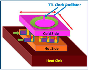
Figure 1. Schematic diagram of the QCM humidity sensor with integrated Peltier module. Reprinted from [30], Copyright 2000, with permission from Elsevier.
Download figure:
Standard image High-resolution imageCMUT is a transducer where the energy transduction is due to changes in capacitance. The CMUT sensor is promising for high-sensitive humidity detection because of its superior properties (e.g. high mass sensitivity, high quality factor (Q), and multiresonant array structure [31]). It is able to detect very small mass change in the zeptogram range (~10−21) with typical resonance frequencies in the 40–50 MHz range, showing higher sensitivity than QCM-based sensors, which are mainly operated in 10 MHz range [32]. In addition, CMUTs are available as multi-channel, multi-membrane structures, which, therefore, are able to do a pattern recognition, thereby eliminating interferences from environmental changes, such as temperature or pressure fluctuations [33]. CMUT sensors functionalized with a mesoporous silica film and a guanidine polymer layer were investigated for humidity sensing (figure 2) [31, 34].
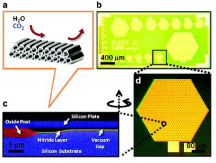
Figure 2. (a) Illustration of a mesoporous silica thin film. (b) Optical picture of a single die, showing an array of multiple elements. (c) Scanning electron microscope (SEM) image of the cross-section of a single CMUT resonator. (d) Optical picture of a single element with 1027 cells. Reprinted with permission from [34]. Copyright 2012 American Chemical Society.
Download figure:
Standard image High-resolution imageSimilar to the sensing mechanism of QCM, FBAR (film bulk acoustic resonators, figure 3) is another well-known gravimetric sensing device, which is operated in the frequency range of some hundreds of MHz to several GHz, with the excitation realized by piezoelectric actuators. FBARs have been extensively investigated to develop oscillators due to their high frequency, high Q factor, and low power consumption [35]. In addition, thanks to their high resonance frequencies, the induced frequency shifts of FBAR sensors by analyte adsorption are much higher than those of QCMs, SAW sensors, and microcantilever sensors, thus sensitivity in absolute frequency change is notably improved. ZnO thin film [36] and graphene oxide [35] film and so on, have been reported as humidity sensing materials for FBAR sensors.

Figure 3. (a) Schematic cross section of a monolithically integrated FBAR. (b) Section of a monolithically integrated FBAR sensor array on a complementary metal oxide semiconductor (CMOS) wafer. Reprinted from [37], Copyright 2009, with permission from Elsevier.
Download figure:
Standard image High-resolution imageMass loading effects also occurs in SAW (surface acoustic waves, figure 4) devices [38, 39], where the phase velocity of surface waves is changed because of the adsorption of water vapour. Surface acoustic waves can be induced by fabricating interdigitated electrodes (IDEs) on a thin piezolelectric layer of ZnO [40], AlN [41, 42], piezoelectric lead zirconate titanate (PZT) [43] deposited on a quartz substrate [44]. For a piezoelectric layer, AlN was proven to be a very good candidate due to its high temperature and chemical stability, good piezoelectricity, and high acoustic velocity [41]. In addition, SAW sensors are composed of an emitter and a receiver configuration of IDEs. The sensitivity to water moisture occurs when a humidity-sensing material film was deposited between the IDEs, for example, a nanostructured metal oxide film [45], polymers [46] or graphene oxide (GO) [47].

Figure 4. (a) Schematic view of a flexible SAW device and (b) a photograph of fabricated flexible devices. Reproduced from [47]. CC BY 3.0.
Download figure:
Standard image High-resolution image1.3. Microcantilevers
A microcantilever can be modelled as a cantilever beam, i.e. with one end fixed and the other free (figure 5) [48]. Microcantilevers can be fabricated to various shapes and are typically composed of silicon, silicon derivatives, or polymers (figure 6).

Figure 5. 3D schematic of a silicon microcantilever integrated with piezoresistors at its fixed end.
Download figure:
Standard image High-resolution image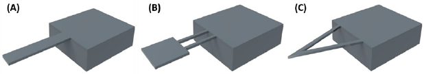
Figure 6. Microcantilevers of different shapes (oblique view): (A) rectangular; (B) double-legged; (C) triangular.
Download figure:
Standard image High-resolution imageTwo operating modes of microcantilevers are used for sensing applications, which are known as static and dynamic modes. The static mode of deflection occurs, when an adsorption of analyte on the cantilever causes differential surface stresses on its upper and lower surfaces, leading to deflections either upwards or downwards depending on the adsorption [48]. The static mode is straightforward because no actuation element is needed. For the dynamic mode, an actuation system to excite the cantilever at resonance is a prerequisite (the discussion about excitation and actuation of microcantilever is presented in section 2). By measuring the eigen frequency of the microcantilever, the mass changes due to adsorption or desorption of analytes can be measured [49, 50]. Similar to the QCM, the resonance frequency of a microcantilever decreases/increases proportional to the mass that adsorbed/desorbed on/from the sensing material [15]. Normally, a long and soft cantilever is required to achieve large deflection for static mode detection. On the contrary, a short and stiff cantilever is required for the dynamic method, where high operation frequency is favourably needed.
The optical detection method [51] is the most widely used to detect and characterize both static and dynamic deflections of microcantilevers. The method involves the reflection of a low-power light or laser beam off the microcantilever onto a segmented photodiode or position-sensitive detector (PSD), where a light-emitting diode (LED) coupled with a lens or laser diode is typically used as a source to generate the low-power light beam (figure 7). The reflected laser beam falls at a certain position when the undeflected microcantilever is fixed, but when the microcantilever deflects due to the adsorption of analytes, a proportional reflection spot shift of the laser beam occurs, and this shift will be recorded by the PSD, which possesses high position resolution and fast response speed. Even though the optical detection tends to be complicated in terms of its optical tool alignment, it offers high-sensitive response and has been already commercially available, in which deflections of microcantilevers in the range of angstroms and nanometers can already be detected (e.g. in an atomic force microscopy (AFM)) [50]. However, this technique still has a distinct limitation as it is sensitive to the optical properties of the atmosphere around the microcantilever. Thus, it is not effective when it is employed for detecting particles in smoky air or volatile organic compounds (VOCs), which can scatter light interfering the original captured signal from the cantilever material. In addition, this optical readout system cannot be used for measuring in opaque liquids, such as blood. Besides, detection systems of high precision and resolution are expensive and not portable [50].
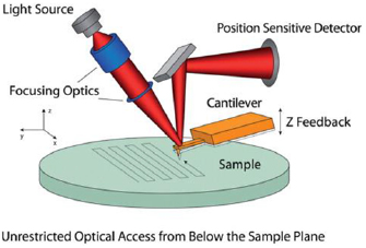
Figure 7. Schematic depicting the optical lever detection system used in AFMs. Light is reflected off the back of a cantilever and read on a detector as the cantilever/probe is raster scanned to measure the topography of the sample. Most of the AFM instrumentation can be located above the sample, allowing for unrestricted optical access from below. Reprinted from [52], Copyright 2009, with permission from Elsevier.
Download figure:
Standard image High-resolution imagePiezoresistive detection is another commonly used method to characterize cantilever deflection. A piezoresistive microcantilever contains embedded piezoresistive materials designed as resistors (i.e. piezoresistors), which are normally arranged in either half or full Wheatstone bridge circuit configuration, to record the stress change along the cantilever axis induced by static or resonant cantilever deflections (figure 8). In case only a single piezoresistor is integrated directly on the mircocantilever, the remaining three resistors will be normally placed on the unstressed frame close to the cantilever or directly on a printed circuit board using commercial electronic components. However, to obtain maximum sensitivity, the piezoresistor (or even four piezoresistors in case of a full Wheatstone bridge integrated on the cantilever, see figure 8) should be positioned as close to the cantilever fixed end as possible. Depending on operation mode, the resistance change can be measured as both static and dynamic signals. Doped single crystal silicon is one of the most common materials that shows a strong piezoresistive effect, in which silicon-based piezoresistive microcantilever with boron doped full Wheatstone bridge has a typical resistance of a few kilo-ohms [53, 54].

Figure 8. Schematic diagram of piezoresistive microcantilever (inclined view).
Download figure:
Standard image High-resolution imageThe benefit of using piezoresistive detection is that the principle works well in both liquid and gas phases, where large arrays of such piezoresistive sensors can be realized and read out simultaneously. Besides, piezoresistive microcantilevers can integrate the readout system on-chip, which consequently shrinks the size of a final system set-up. Therefore, bulky and expensive instrumentation is not needed in the electrical characterization of the devices [55–57]. However, current flow through the piezoresistive microcantilever is always required in the piezoresistive detection technique, which may result in additional dissipation of heat inducing associated thermal drifts [58, 59]. Thus, any variations in the thermal conductivity of the environment will result in fluctuations of the cantilever temperature that, in turn, may lead to parasitic piezoresistance changes and cantilever deflections [60]. In the reported works about piezoresistive microcantilevers for sensing applications, these thermal effects can be eliminated, e.g. by using a bare unfunctionalized microcantilever as reference sensor [61].
However, miniature gravimetric sensors such as SAW sensors, FBAR, QCM sensors, and optical-detection-based microcantilever sensors require either high-frequency measuring equipment or AFM-based detection systems, which are large and expensive [62]. Whereas, piezoresistive microcantilevers and CMUT-based humidity sensors are being manufactured with fabrication techniques similar to those in integrated circuit (IC) manufacturing. Thus, they can be compatible with complementary metal oxide semiconductor (CMOS)-based processes and integrated to the specialized reading-out circuit as part of a sensing network or as portable humidity sensors. Besides, unlike SAW or QCM, which are not small enough to be incorporated in large numbers as an array (necessary to achieve selectivity), FBAR, microcantilevers, and CMUT are true microelectromechanical system (MEMS), and it is possible to accommodate sensors arrays on a single small chip. Moreover, unlike other resonant elements such as quartz crystals, Si-based MEMS resonators have the potential for higher levels of integration with microelectronics at the die or package level, higher reliability, and lower failure rates [63]. These advantages can lead to reduced cost and specialized circuits that can have enhanced performance and more functionality [63]. Therefore, vapour detection using highly sensitive miniaturized silicon resonant sensors is of great interest for many applications, including consumer, industrial, and environmental applications.
In this review paper, we aim to present a comprehensive overview of research and development on piezoresistive microcantilever-based humidity sensing. The paper was organized according to the components of the piezoresistive microcantilever sensors and their corresponding features as follows: it begins with a brief introduction to humidity sensing, gravimetric humidity sensors and microcantilever technology including standard read-out principles; the gravimetric sensing method using microcantilevers is described in section 2; the application of microcantilever-based sensors for environmental monitoring is subsequently presented in section 3; humidity-sensing elements based on different sensing materials and their fabrication techniques are comprised in section 4; after that, the properties of recently designed and fabricated piezoresistive microcantilever-based humidity sensors and their comparison with other MEMS-based gravimetric devices for humidity sensing are showed in section 5. At last, we will conclude the current achievements and look into the future.
2. Microcantilever-based gravimetric sensing
Chemical and physical interactions between a MEMS transducer and its atmospheric environment often result in binding-induced mass-change and chemically induced spring constant-change (stiffness-change). The resonant frequency of a MEMS resonator decreases if the mass increases or increases if the spring constant increases. Microcantilevers are one of the most common types of resonators that are used for gravimetric sensing [18]. Their simplicity and small structure size lead to possibility for fabricating high performance devices with good reproducibility [19]. In this section, we will review the gravimetric sensing mechanism and the actuation methods used for microcantilevers.
The effects of stiffness and mass change on the shift Δf of the nth resonant mode frequency f n can be approximated by equation (1), assuming uniform changes Δm and Δk of mass m and stiffness k, respectively:
For many applications, the mass-change effect is dominant compared to the stiffness-change effect. Therefore, the stiffness term in equation (1) is often neglected. Thus, the mass-change sensitivity can be expressed as:

The minimum detectable mass is thus related to the ratio of mass and resonance frequency of the beam, as well as the location of the added mass on the cantilever. Beam size, geometry, fluidic environment, and the quality factor of the material also play crucial roles. For instance, the minimum detectable mass of the gravimetric sensor is inversely proportional to Q [64, 65].
The Q factor is commonly used to quantify energy dissipation in mechanical systems. It is inversely proportional to the damping coefficient and can be defined by equations (4) and (5) where W0 and ΔW are the mechanical energy accumulated and the energy dissipated per vibration cycle, respectively. It is a measure of the degree of the resonance peak sharpness and is related to the time constant of exponentially decaying oscillator amplitudes during ring-down processes as illustrated in figures 9(a) and (b). In resonant sensors, the Q factor therefore plays a crucial role, i.e. for high resolution and efficiency, high Q factors are required [18, 59].


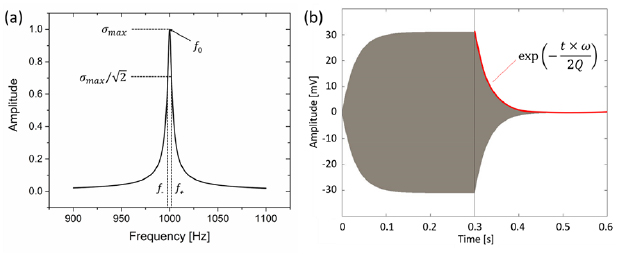
Figure 9. (a) Frequency response and (b) ring-down response of a mechanical resonator. Reprinted from [59]. © IOP Publishing Ltd. All rights reserved.
Download figure:
Standard image High-resolution imageIn comparison to other resonance elements such as quartz crystals (e.g. QCM), MEMS resonators have the potential for higher degrees of integration with microelectronics at the die or package level. The actuator integration can lead to systems with enhanced performance and functionality. Piezoresistive transducers show very suitable properties for mass-sensing applications, since the sensitivity increases with decreasing resonator mass and piezoresistivity enhances at shrinking scales, while other transduction methods lose efficiency [19].
2.1. Resonant excitation
Resonant sensors are among the most sensitive and precise devices for many applications, due to the relatively simple procedure of high-precision frequency measurement compared to the requirements of voltage or current measurement at similar level of precision [19]. There are various resonant modes, which can be used for a resonant cantilever sensor (figure 10). Out-of-plane modes including transverse bending (B) and torsion motion (C), in-plane modes including lateral bending (D) and longitudinal extensional motion (E). Each mode exhibits resonance gains when excited at its characteristic frequency. The resonance frequencies (table 1) are defined by the cantilever geometry, material density, and spring constant [64].
Table 1. Resonant frequency of different modes of a homogenous cantilever.
| Mode | Resonant frequency | Constant (ci,n) | Spring constant (ki) |
|---|---|---|---|
| Transverse |  |
 |
 |
| Torsional |  |
 |
 |
| Lateral |  |
 |
 |
| Longitudinal |  |
 |
 |
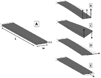
Figure 10. (A) Cantilever geometry and eigenmodes of a cantilever resonator within (B) transverse bending, (C) torsion motion, (D) lateral bending, (E) longitudinal extension motion. Reprinted from [64], Copyright 2012, with permission from Elsevier.
Download figure:
Standard image High-resolution imageWhere L is the length, w is the width, t is the thickness, respectively, of the cantilever, E is the Young's modulus of the cantilever material, m is the cantilever mass, n is a positive integer and λn is the eigenvalue given by the nth positive root of 1 + cos(λn) cosh(λn) = 0. The first three eigenvalues are 1.875, 4.694, and 7.855. G = E/[2(1 + ν)] is the shear modulus, ν is the Poisson ratio, Ip = (tw3 + t3w)/12 is the polar moment of inertia, and ξ is a shear coefficient defined as [64]:

For typical cantilever designs, out-of-plane modes have higher amplitudes than in-plane modes, while in-plane modes can reach high Q factors even in viscous media [19, 64].
To measure the resonance frequency, the cantilever must be excited by a particular driving force. Resonance excitation can be realised by a variety of different techniques, depending on diverse cantilever designs. Therefore, the excitation components can either be cantilever- integrated or externally added.
2.1.1. Piezoelectric excitation.
One of the most prevalent technologies in electronic applications is the piezoelectric resonator. Material having large coupling coefficients can provide efficient reciprocal conversion of electrical and mechanical energy [19]. Piezoelectric excitation of cantilevers can be realized by an external piezoactuator die underneath the cantilever frame [58] or by integrated actuator layers [66, 67]. A big advantage of integrated piezoelectric thin-film layers is that they can be used as both actuating and sensing parts. The main technical difficulty in working with piezoelectric material at the micro-scale is their implementation into mainstream microelectronics-fabrication processes [19]. Considerable efforts have been made in designing and implementing multi-mask patterning techniques into surface machining processes. As piezoactive materials, crystals with high piezoelectric coupling efficiency, such as AlN, are used. The piezolayers are usually sandwiched between two similar-thin electrode layers [68]. It is reported that nanometer-thick layers of AlN show piezoelectric coupling coefficients on high-frequency resonators close to those of bulk crystals [69, 70].
2.1.2. Electromagnetic excitation.
Another form to actuate a microcantilever is using electromagnetic interaction. There are different ways to realize this kind of excitation, but all of them need an external magnetic field or current. The simplest way, shown in figure 11, is a conductive loop integrated on the piezoresistive cantilever with a current  passed through. When the entire structure is immersed in a magnetic field
  parallel to the cantilever axis, a Lorentz force
  , which is induced in the loop, acts on the cantilever letting the spring-beam deflect out of plane [71]. It is described by:
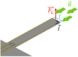
Figure 11. Electromagnetic actuation principle using a conductive loop on the cantilever perpendicular to an external magnetic field  leading to a force
  .
.
Download figure:
Standard image High-resolution imageCoils and permanent magnets can be used as the magnetic field sources. The main advantage of using a Helmholtz coil is the fact that the magnetic field vector  in the central point is uniform and can be manipulated (figure 11). Using permanent magnets, they must be placed in such a way that magnetic field lines at the cantilever are perpendicular to the active part of the Lorentz loop (l) [72].
Another way to realize electromagnetic excitation, is by evaporating a magnetic layer on the cantilever and applying an external magnetic field [73]. Similar to piezoelectric actuation, this approach suffers from the need of integration of actuator-film deposition into the cantilever-fabrication process, but does not require conductive tracks and contacts to the magnetic layer [74].
2.1.3. Electrothermal excitation.
Less known technique in terms of resonant actuation is the electrothermal excitation. The efficiency of the thermal transduction (force to heat ratio) is dependent on the thermal time constant associated with the structure to be excited. Correspondingly, the temperature difference generated by an input alternating electrothermal power source strongly decreases at period times above an upper limit given by the thermal time constant τ. This fundamental behaviour has led to the traditional belief that thermal actuators are slow and can only be used for low-frequency applications [19]. However, in case of microstructures thermal resonance excitation could be proven by several studies [75–79]. The thermal time constant for a specific resonant structure scales much faster (second order dependency) than the resonance frequency (linear dependence) as the dimensions of the structure reduce [18]. In other words, the temperature of a structure follows the input power much faster as the dimensions are scaled down. Moreover, the materials used for microcantilever fabrication (e.g. silicon), often have relatively high thermal conductivities, leading to fast heat transfer [19, 72].
Thermal transducers can be used not only for actuation, but are also perfectly compatible with piezoresistive transducers, owing to the possibility of simultaneous fabrication and their ease of implementation (figure 12) [15, 79]. Thermal actuators on microcantilevers can be realized by resistive heating loops. For all that, it only requires a conductive material through which an electrical current is passed through to locally generate heat. Once the frequency of the thermal wave matches the resonance frequency of the structure, a mechanical vibration is efficiently excited [19].
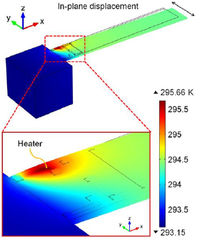
Figure 12. FEM simulation of a diffused heating actuator for in-plane excitation of cantilever bending. Reprinted from [79], Copyright 2015, with permission from Elsevier.
Download figure:
Standard image High-resolution imageElectrothermal actuators can be driven by two different techniques. The 1-ω and the 2-ω techniques use a heating current with the same (ωAC = 2πfn, i.e. f AC = f n) and the half frequency (2ωAC = 2πfn, i.e. f AC = f n/2) of the excited cantilever resonance f n, respectively [80]. For the 1-ω technique, a current has to be applied composed of DC and AC components VDC and VAC, respectively. Then, the electrothermally generated heating power is expressed by:

where t is the time, Rh is the heating resistor and Vh is the heating voltage.
The oscillation amplitude increases linearly with the dissipated power. Thus, the DC offset dominates the actuation via the second summand in equation (8), if it is at least as high as the AC amplitude. For the 2-ω technique, only AC currents are used, i.e. VDC = 0. In this case, the frequencies of the actuation and deflection signals are separated thus parasitic electromagnetic signal interferences can be avoided [71, 77].
The 1-ω technique has higher power efficiency than the 2-ω technique, which should therefore be considered especially for mobile applications. In figure 12, the finite element modelling (FEM) simulation of a self-actuated Si-cantilever using a p -doped heating resistor is shown.
For an increased efficiency, thermal actuation can also be realized by the bimorph effect using materials of different thermal expansion coefficients (figure 13) [71], which needs the integration of an additional layer und thus relinquishes the advantage of simple implementation together with piezoresistor fabrication. Furthermore, external excitation was shown by induced thermal effects on micro structures by using low-power lasers [81].

Figure 13. Integrated out-of-plane heating actuator using layers with different expansion coefficients. Reprinted from [71], Copyright 2018, with permission from Elsevier.
Download figure:
Standard image High-resolution image2.2. On-line frequency tracking
The most straightforward method to detect the resonance frequency of a mechanical device is by sweeping the frequency of an AC excitation signal around the frequency of the corresponding amplitude maximum. This method is common especially in laboratory settings but is not suitable for on-line measurements due to its slow sweep rates needed for proper frequency resolution. Another technique is to excite the resonator with a fixed stable signal at a frequency that is slightly different (typically higher) than the resonant frequency of the device. In this case, changes in resonant frequency will be converted to changes in amplitude of the output signal and can then be related back to the measurand [19, 82]. With this method, on-line monitoring can be achieved, but frequency is not tracked. Additional Q-factor changes caused by the environment may lead to miss interpretations.
A more practical method is to place a two-port resonant device into the feedback loop of a properly designed electronic circuit to form an oscillating system, that follows the desired resonance frequency [19]. Corresponding feedback loops can be active or passive units. As feedback loop, a phase locked loop (PLL) circuit can be used. This method is common for on-line resonance frequency tracking using instruments like a lock-in-amplifier (e.g. Zurich Instruments HF2LI and MFLI) [83, 84] or individual circuits [53] and can reach very high frequency stability. PLL circuits are active controlling circuits and consist of three core elements: a phase detector, a loop filter and a voltage-controlled oscillator (VCO) as illustrated in figure 14(a). This can be realized by analogue and digital components or by software. Typically, software-based PLL circuits are slower than their hardware-based counterparts but can be adapted to emerging, more complicated demands, e.g. non-linear resonance behaviour [58].
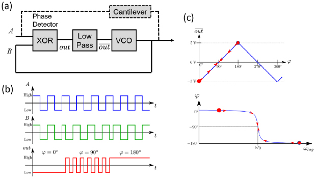
Figure 14. (a) Block diagram of phase locked loop (PLL) circuit, (b) input and output signals of phase detector and loop filter, (c) relation of resonator phase and controlling signal.
Download figure:
Standard image High-resolution imageThe phase detector detects the phase difference ϕ between the input and output signals of the resonator and generates a ϕ-depended output signal vout(ϕ). This is converted to an increasing or decreasing voltage by the loop filter and further results into an increasing or decreasing frequency of the output signal of the VCO. The working principle of a PLL is illustrated in figures 14(b) and (c) [53, 58]: In this case, phase detection is realized using a simple XOR-gate. This generates a pulse width modulation signal with a duty of 50% at 90° phase sift. Thus, a loop filter formed by a low pass, creates an increasing and decreasing signal at a phase difference of <90° and >90°, followed by a frequency increase and decrease by the VCO, respectively. The respective locking phase can be achieved by the appropriate choice of the phase detector and loop filter. The PLL circuit shown in figure 14 locks towards 90° phase shift with a phase dynamic of 180°.
For a passive configuration, the resonator needs to be engaged in a positive feedback loop consisting of amplifying circuitry with an appropriate phase shift [85]. Therefore, at power up, the noise present in the positive feedback loop becomes amplified and filtered. For a constructive growth and a sustaining oscillation, the linear gain around the loop must be larger than unity and the in-resonance phase shift must be determined. Moreover, a reasonably good value of peak amplitude is needed [19]. Toledo et al presented such a feedback loop based on discrete components, combined with an automatic gain control (AGC). The circuit is shown in figure 15. In connection to the mechanical resonator, a variable-gain stage introduces the gain necessary to obtain an overall loop gain of >1 at the resonance frequency. At its output, a follower stage is introduced to avoid loading problems. A passive low-pass filter prevents higher modes from oscillating. Furthermore, to regulate the output voltage amplitude, the amplifying feedback loop is integrated with an AGC. Therefore, the estimated output amplitude using a passive envelope detector and the control input vAGC are compared and integrated. The obtained signal serves to control the loop gain, avoiding a saturation of the amplifiers [86].
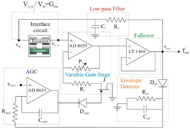
Figure 15. Positive amplifying feedback loop, combined with an automatic gain control (AGC) [86] 2016 © Springer-Verlag Berlin Heidelberg 2016. With permission of Springer.
Download figure:
Standard image High-resolution imageSimple oscillator circuits can reduce the size, cost and power consumption of the system comparing to PLL circuits. For all measurement methods, higher Q factors result in a better resolution of the sensor [19].
2.3. Parasitic excitation-detection feedthrough
Parasitic feedthrough often is a limiting factor for sensors. The small dimensions in MEMS sensors make them susceptible to internal coupling effects, especially [87]. While many interferences can be minimized by frequency filters, this does not apply to interferences induced by excitation signals of resonant sensors, which usually have the same frequency as the measurement signal. Depending on the excitation and read-out techniques, parasitic excitation feedthrough can lead to offset and line-shape deformation of the measurement signal as well as phase distortions. In many cases, this leads to an asymmetric resonance behaviour, which is schematically illustrated in the spectral shapes of amplitude and phase as shown in figure 16 [59, 87].
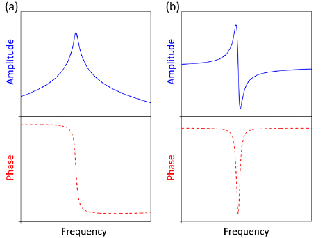
Figure 16. Illustration of amplitude and phase of (a) a symmetric and (b) asymmetric resonance line shape.
Download figure:
Standard image High-resolution imageThe asymmetric line shape can be observed in many types of resonant MEMS sensors [19, 59, 86, 87]. It is induced by the phase differences of the mechanical resonance output and a parasitic feedthrough of the actuation signal. The phase shift in resonance leads to the asymmetric coupling of both signals as illustrated in figure 17 [59].
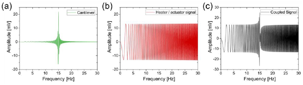
Figure 17. (a) Resonance signal, (b) parasitic signal and (c) interference of both signals with asymmetric line shape.
Download figure:
Standard image High-resolution imageThis phenomenon can create massive problems for frequency-tracking systems. A PLL circuit is based on the phase difference of frequencies higher and lower than the resonance frequency (e.g. 0 > ϕ(f < f 0) > −90°, −90° < ϕ(f > f 0) < −180°). This requirement is not fulfilled in case of asymmetric frequency response. In addition, the measured amplitude can be lowered by interference.
There are several approaches to avoid or compensate such excitation crosstalk and the corresponding asymmetric resonance line shape. In general, the spatial separation of excitation and read-out elements will lower parasitic crosstalk. In addition, the use of a dummy structure that is not stimulated mechanically or differential signal out-reading can compensate the feedthrough by subtracting the respective output signals of the active component with those of the dummy [67, 87, 88]. In the same way, an electrical circuit can be used for the reconstruction of parasitic couplings [89–91].
In fact, the techniques used for excitation and detection can affect the measured frequency response in different ways. This holds, although sensors may be of similar geometry. Since the frequency response is an indicator of the mode characteristics, it is possible that the used excitation technique may also affect other related characteristics, such as sensitivity [64]. Therefore, a very important criterion for comparing methods of the resonant MEMS actuation is the impact of the chosen method on the crosstalk superimposed to the signal detection [72].
3. Environmental sensing using microcantilevers
Microcantilevers are among the simplest MEMS resonators, which are widely used for the detection of chemical and biological analytes. In the past decades, microcantilevers and nanocantilevers have been investigated by many groups as particulate, humidity, chemical and biological sensors due to their extraordinary sensitivities to mass changes [15, 79, 92–95]. After being coated with thin polymer films, porous inorganic films, metal oxide (MOX) nanostructures and MOX nanostructure/polymer hybrids, microcantilevers can act as physical, chemical or biological sensors. Microcantilevers have several prospective advantages over the conventional technologies as they are highly sensitive, inexpensive, robust, high-throughput, mass-produced, require minimal sample and low energy, have a rapid response time and follow a nonhazardous label-free procedure [48, 96, 97].
In 1993, Tortonese et al originally proposed and developed a piezoresistive microcantilever readout method for AFM applications [98]. In a piezoresistive microcantilever, the recognition and transduction function are integrated separately in the same device, where the recognition elements are fabricated separated from the readout element (piezoresistor). The analyte interacts in a more or less selective way with the recognition (or sensing) element, thus the microcantilevers can be employed as miniaturized analytical sensor devices that can automatically deliver real-time and on-line information on the presence of specific compounds or ions, by detecting their effect on deflection (static) and resonance response (dynamic) caused by mass loading, surface stress variation, or changes in damping conditions. However, it is worth noting that, since the piezoresistor has to be embedded in the cantilever, the fabrication of piezoresistive microcantilevers with integrated sensing material is more complicated and elaborate.
3.1. Particulate matter sensing
Cantilever-based sensors equipped with different types of actuation and sensing elements have been produced and employed in the last few years for monitoring particulate matter (PM) or particle mass concentration, which is one of the main indicators of air pollution brought into the air by various sources (i.e. either by nature or human activities). Several of them that provide good mass resolutions (i.e. ranging from picogram down to femtogram) are Si microcantilever array with nanoscale thickness and laser Doppler vibrometer-based detection [99], paddle-type silicon microcantilever with mounted PZT actuator and optical fiber detection [100], AlN/Si microcantilever with helium-neon-laser-based optical detection [101], piezoresistive Si microcantilever with external piezoelectric stack actuator [53, 102–105], self-actuating piezoresistive Si microcantilever with integrated heating resistors [59, 77, 103], vertical Si nanocantilever array with electron imaging detection [92, 106–108] and electrothermal piezoresistive Si microcantilever with integrated nanopillar array on its top surface [107]. It can be seen from those listed sensors, all the realized micro-/nanocantilevers are made of silicon materials (i.e. bulk silicon or silicon on insulator (SOI)) due to their mature material properties, well-established micro-/nanomachining technology, and low-cost batch fabrication. In case of particle sampling, since no additional material has been introduced or coated on cantilever surfaces as a sensing element like in hybrid organic/inorganic gas sensors, thus, to efficiently collect the flowing airborne particles onto the surfaces of resonant cantilevers, the sensors have to be combined with a particle sampler or PM precipitator. PM sampling methods that have been introduced to be integrated with MEMS/NEMS resonators are mainly based on electrophoresis [54, 105], thermophoresis [109] and inertial impaction methods [110, 111]. Among them, electrostatic or electrophoretic sampling is the most favorable technique due to its large particle sampling efficiency and easiness for device miniaturization (i.e. neither bulky pump nor large heating element is required for the integrated system). Therefore, Wasisto et al have combined piezoresistive microcantilevers with a small custom-built electrophoretic sampler to create handheld cantilever-based airborne particle detector (CANTOR) for monitoring mass concentration of different ultrafine particles or nanoscale particles in air, in which they have enhanced the first design of partially integrated portable CANTOR-1 [104] to a fully integrated wearable CANTOR-2 [79] (see figures 18(a) and (b)).

Figure 18. (a) Electrostatic sampler of partially integrated portable CANTOR-1. Reproduced from [104]. CC BY 3.0. (b) Fully integrated wearable CANTOR-2. Reprinted from [79], Copyright 2015, with permission from Elsevier. The mounted piezoresistive cantilever sensors can be used not only for detecting airborne nanoparticles, but also humidity, because of the high versatility of the developed CANTOR system.
Download figure:
Standard image High-resolution imageBeing compared to the other up-to-date MEMS/NEMS particle detectors worldwide based on FBAR [109], thermally actuated MEMS [112] and fiber nanostring [113], only CANTOR-2 has been completely developed as a wearable personal detector for monitoring airborne nanoparticles. The other prototypes cannot meet the requirement because they still need large equipment during their measurements (e.g. pump, microscope, lock-in amplifier, or laser Doppler vibrometer). By having a total device volume of 540 cm3, weight of 375 g, and power consumption of 1.25 W in the current version, the developed CANTOR-2 offers a very good portability and can be easily held or worn by workers during their activities. This battery-operated device has a limit of detection (LOD) of 5 µg m−3 and a particle sampling time of 6 s [79] Besides the piezoresistive microcantilever sensor, miniaturized electronic circuitries, microfilter, impactor, phase-locked loop component, and LCD were all integrated into a compact system. In this case, as the system is versatile, CANTOR-2 can be integrated with such piezoresistive cantilever-based humidity sensors in an array configuration, so that the system will not only be able to detect the airborne nanoparticles, but also to monitor RH at the surrounding workplaces. Moreover, to overcome the regeneration issue related to the instability performance of the sensor after being fully loaded with particles, a simple but effective dry cleaning method was introduced into their next generation of CANTOR-3 [59]. This has offered an efficient alternative to other particle removal methods (e.g. PDMS-based detachment and ultrasonication in a wet chemical bath [114]. By operating the CANTOR sampler under reversed bias, a heavily loaded piezoresistive cantilever can be refreshed without dissembling it from the portable system, in which 31% cleaning of the deposited particles has been demonstrated after 3.33 h [59].
3.2. Gas and volatile organic compound sensing
In 2000, a first piezoresistive silicon microcantilever coated with photoresist polymer of 10 µm in thickness was exposed to vapours of various alcohols, and a corresponding detection limit below 10 ppm was determined [57]. Later, a compact piezoresistive microcantilever-based gas-sensing system was presented by Lange et al, including system-integrated resistors for resonant excitation (heating resistor) and detection (piezoresistor), driving circuitry and analogue or digital signal-processing circuitry on the same chip. Using such a thermal-excited piezoresistive microcantilever, this group was able to detect gas-phase concentrations of n-octane or toluene in the single-ppm range [115]. Subsequently, Pinnaduwage et al demonstrated that by depositing 4-mercaptobenzoic acid (4-MBA) SAMs on a gold-coated piezoresistive microcantilever, a detection limit for pentaerythritol tetranitrate and hexahydro-1,3,5-triazine vapours in the low parts-per-trillion level could be achieved within a few seconds; besides, with a homemade circuit, a microcantilever could be integrated into a compact, nonoptical, handheld device [62]. In 2009, similar piezoresistive microcantilever arrays were fabricated and one-side-coated with different polymers (poly-vinyl alcohol, poly-ethylene imine (PEI), poly-acryl amide, and poly-vinyl pyrrolidone). The resistance change of Wheatstone bridge piezoresistors due to bending of the polymer-coated cantilevers was measured, individual alkanes in a homologous series were selectively discriminated, and a sub-ppm detection limit was achieved [116]. Recently, Boudjiet et al proved that uncoated piezoresistive microcantilevers of different shapes (rectangular, T- and U-shapes) can achieve a detection limit of about 0.11 mg l−1 of H2 gas mass variations in N2 (corresponding to a concentration of 100 ppm of H2 in N2), which is much better than the current state of the art for uncoated mechanical resonators [117]. Besides, Porter et al and Kooser et al reported a gas-detecting method by embedding piezoresistive microcantilever into polymeric material, e.g. poly(ethylene oxide); piezoresistance changes could be measured, when the polymer underwent a volumetric contraction upon CO exposure, owing to a catalytic carboxylation of poly(ethylene oxide) by the CO [118, 119].
4. Humidity-sensitive materials and nanostructures
Humidity sensing material is another important part of a humidity sensor besides the sensing principle. In 1938, an electrolytic humidity sensor using lithium chloride (LiCl) as sensing material was reported by Dunmore [120], while in the past eighty years, numerous materials were investigated as humidity-sensing elements, and many efforts have been done to group or classify the sensing elements [2, 3, 12, 121, 122]. In this paper, according to the material property, we divide these sensing materials as three groups: metal oxides (ceramics), organic polymers and organic/inorganic hybrid composites (polymer/ceramics). Humidity sensors using nanowires, nanofibers, nanorods, and other nanostructures are subclasses of the metal oxide (ceramic) type. It should be noted that due to fragility and miniaturization of microcantilevers, only such methods and materials, which have proven to be utilized or fabricated on cantilevers, are discussed in this paper.
Instead of the conventional resistive- or capacitive-based measurements, which require materials to be high-conductive and dielectric, the deflection induced by surface change or the resonance frequency shift caused by mass change would be detected when we use microcantilever for humidity detection. Thus, the hygroscopic property of the sensing material is very important. There are two methods to develop an excellent hygroscopic sensing material, i.e. creation of a completely novel material and improvement of the property of an existing material [123].
4.1. Metal oxides/ceramics
Ceramics were used as humidity sensing materials due to the effective water adsorption on their surface. Compared to polymers, they have shown relatively good chemical and thermal stability. For metal oxide/ceramic-based microcantilever humidity sensors, sensitivity is determined by the deposited materials. At the same time, to have high sensitivities in both static and dynamic measurements, a high surface area and sufficient flexibility is needed for the cantilever functionalization. Besides, it should be noted that the uniformity, thickness, and size of nanostructures of the sensing material film are also important to the property of the microcantilever sensors [23, 124]. Therefore, many attempts have been made to achieve high surface-area-to-volume ratio, by coating them with porous materials and 1D nanostructures, or etching pillars on the cantilevers [125–128]. However, it is hard to grow nanostructures on cantilevers reproducibly, besides it is difficult to control the mechanical properties of these cantilevers due to their bilayer structures.
Porous Al2O3 has been demonstrated to be very sensitive to low humidity levels due to its small pore radius and the electron-tunnelling effect inside the condensed immobile water layers [3, 127, 129, 130]. Besides, it is independent of temperature changes (from 25 °C to 80 °C) at nearly the entire range of RH, thus Al2O3 is one of the most favourable ceramic materials being used for moisture sensing. Shi et al reported a method of depositing Al2O3 on a V-shaped commercial silicon microcantilever (180 µm in length, 25 µm in leg width, 1 µm in thickness, Veeco Instruments, Santa Barbara, CA), the microcantilever was one-side coated with a 3 nm-chromium thin film and a 20 nm-gold layer, subsequently. Then, an Al-layer of 100 nm in thickness was deposited on another side of the microcantilever. Afterwards, the Al-layer was oxidized in a high-vacuum chamber with oxygen flowing through at 100 °C, all the depositions were performed by e-beam evaporation [127]. In comparison with the conventional direct deposition of Al2O3, the aluminium oxidation led to compact thin oxide layers [127].
Later, Lee et al and Kappa et al fabricated cantilevers with hexagonally ordered nanowells from anodic aluminium oxide (AAO), which had improved mass and stress sensitivities compared to corresponding solid cantilevers due to the large surface area and low modulus of their porous structures [126, 131]. Hexagonally well-ordered nanowells were prepared on the cantilever by successive electropolishing, anodization, wet-etching and a second anodization. After a further phosphoric acid wet-etching step, nanowells of 2 µm in thickness, 50 nm in diameter, 100 nm in spacing were achieved, as shown in figure 19 [126].
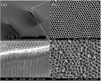
Figure 19. SEM images of AAO cantilevers at different magnifications: (a) AAO cantilevers covered with a 30 nm-thick gold layer, (b) enlarged SEM image of (a) and (c) cross-sectional SEM image of the nanowells, (d) AAO cantilevers covered with a 120 nm-thick gold layer. Reprinted from [126], Copyright 2009, with permission from Elsevier.
Download figure:
Standard image High-resolution imageZnO nanostructures, especially 1D ZnO nanostructures, have attracted great attention as humidity sensing materials due to their high surface-to-volume ratio and numerous chemically active centres [26, 132, 133]. Many efforts have been done to deposit ZnO nanostructures on QCM. In this case, QCM sensors based on nanoparticles [132, 134], nanowires [25], nanotetrapods [133], nanoneedles [26] were proposed and fabricated for high-sensitive humidity sensing. However, due to their slender and fragile structure, it is hard to fabricate ZnO nanostructures on silicon microcantilevers, since a spin-coating technique and high-temperature or high-pressure conditions are normally needed for ZnO nanostructure deposition [135–137].
In 2017, we fabricated ZnO nanorods on commercial microcantilevers (3 mm × 100 µm × 25 µm; CAN30-1-2; CiS Forschungsinstitut für Mikrosensorik GmbH; www.cismst.org) by dipping the cantilever free end into an aqueous solution consisting of zinc nitrate (Zn(NO3)2) and hexamethyleneteramine (HMT, C6H12N4). A seed-layer was prepared in advance by dipping the cantilever into a solution of zinc acetate dihydrate (Zn(Ac)2·2H2O), sodium hydrate (NaOH), and methanol. However, the deposited ZnO nanorods film was not uniform and morphology and thickness were poorly reproducible [16, 138, 139]. Recently, we developed a DC-sputtering/oxidizing and chemical-bath-deposition (CBD)-based two-step method for reproducible ZnO array growth, which can be integrated into a microcantilever fabrication process, where standard silicon micromachining techniques were used [15, 16, 139].
Fabrication starts from an n-type bulk silicon wafer using n+ doping by phosphorus diffusion to fabricate the substrate contact. Subsequently, p - and p +-doping of a heating resistor and a full Wheatstone bridge, were completed by boron diffusion. Thermal oxide patterned by photolithography was used as mask. Then, a compact and uniform thin ZnO seed layer for ZnO nanorods growth was prepared by DC sputtering and a subsequent oxidizing step. After that, chromium and gold were deposited as a metallization to create connection pads to the heating resistor and the Wheatstone bridge. Then, the wafer was dry-etched to achieve the expected cantilever thickness, and put up-surface-down into the solution of (Zn(NO3)2) and HTM for ZnO nanorods growth. The completed microcantilever with ZnO nanorods was obtained after a final cantilever back-side etching (figure 20). For the details, we refer to [15, 139]. In addition, by switching the series of sequential steps of front- and back-dry etching, the sputtering/oxidizing and deposition of ZnO nanorods can also selectively achieved on the backside surface of the microcantilevers (figure 21). Compared to other methods, this process can produce a homogenous and compact ZnO seed layer on the cantilever, which is essential for the uniform and reproducible growth of ZnO nanorods by CBD. Compared to the cantilevers coated with random aligned and interconnected structures, which have long recovery time induced by capillary condensation, microcantilevers with nanorods grown by this method have uniform size, shape and distribution, all the gaps are vertically aligned and opened to the ambient environment. Thus, the adsorption efficiency of gas/water molecules onto the nanorods is notably improved (i.e. sensing results are described in section 5.3).
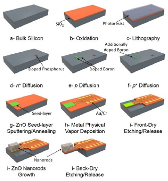
Figure 20. Schematic diagram of the fabrication steps of the microcantilever sensor with ZnO nanorods on its top surface. Reprinted from [15], Copyright 2018, with permission from Elsevier.
Download figure:
Standard image High-resolution image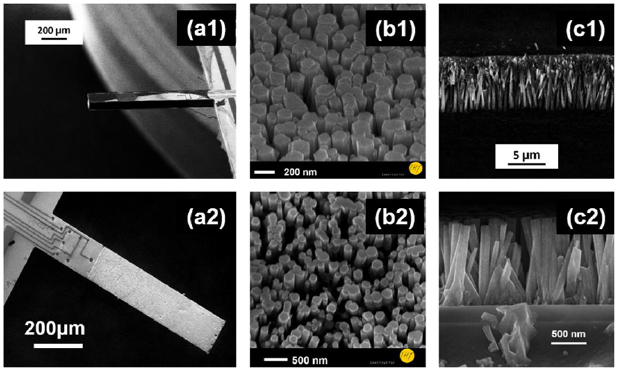
Figure 21. SEM graphs of microcantilever with selectively ZnO deposition on its back-side (1) and front-side (2): oblique view (a1) and (a2), magnified declined-overview (b1) and (b2) and magnified cross-sectional view (c1) and (c2).
Download figure:
Standard image High-resolution imageShortly after our reports, a similar method was published by Schlur et al on a sputtered and oxidized ZnO thin film deposited as a seed layer on a commercial tipless-force-modulation (TL-FM) microcantilever, on which ZnO nanorods were subsequently grown [140]. These ZnO nanorods were then etched to nanotubes (figure 22) in a mixture of aqueous ammonia solution (NH3(aq), 30%) and cetyltrimethyl ammonium bromide (CTAB, purity ⩾ 99%). Thus, the surface-to-volume ratio was further enhanced.

Figure 22. SEM top view of cantilever covered by ZnO nanotubes. These nanotubes are obtained by the dissolution during 1.75 h of ZnO nanorods in a solution containing (a) 0.75 wt% of CTAB and 0.75 wt% of NH3(aq) and (b) 0.5 wt% of CTAB and 0.5 wt% of NH3(aq). Inset: zoom of the obtained nanotube. Reproduced from [140]. CC BY 4.0.
Download figure:
Standard image High-resolution image4.2. Organic polymers
Polymeric humidity sensors have been widely studied in research and applied in industry for more than 30 years, because of their advantages (e.g. high sensitivity, low cost, and simple fabrication techniques [141]). Porous polymer thin films filled with micro-pores for water condensation were used as sensing materials [3]. Traditionally, similar to ceramic materials, polymeric films were used in resistive and capacitive sensors due to their humidity-depending conductivity and hydrophobicity [142]. It should be noted that by using polymers, high sensitivity and selectivity can be obtained if strong and specific chemical interactions between the sensing material and the water molecules are well designed, while good reversibility and short response/recovery times are possible by selecting weak interactions, either physical or chemical. This freedom of design cannot be offered by pure ceramic materials [134, 143]. Furthermore, compared to ceramic materials, the polymeric ones show superiority in performance because of their high chemical stability, wide range of operating temperatures, and fast response to humidity changes [144].
For a microcantilever-based sensor, when it was coated with receptor layers specific to water molecules, sensor signals can be attributed to humidity detection. To detect moisture present in air, cantilevers are typically functionalized with a film that specifically adsorbs water molecules (figure 23).
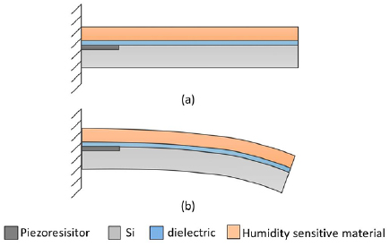
Figure 23. Schematic of a microcantilever piezoresistive humidity sensor: (a) the shape of the microcantilever before uptake of water molecules; (b) after uptake of water molecules. Reproduced from [14]. CC BY 4.0.
Download figure:
Standard image High-resolution imageSurface modification of commercial AFM-microcantilevers was done with phosphoric acid and gelatine to offer both high sensitivity and specificity. Both coatings were achieved by placing a drop of solution on a glass slice and sliding the cantilever into solution until one side of the cantilever is completely wet [145], then it is dried in a desiccator for two days. Gerlach et al, Ma et al, and Huang et al prepared polyimide layers for humidity sensing materials by spin-coating on microcantilevers and membranes [14, 60, 146], before the cantilever or membrane was released by anisotropic dry etching.
Poly(3,4-ethylenedioxythiophene)/poly-styrene-sulfonic acid (PEDOT/PSS) has attracted lot of attention as an appropriate humidity-sensing material. Compared to other polythiophenes, PEDOT/PSS exhibits good electrochemical, ambient, and thermal stability. Besides, it benefits from high conductivity and a simple fabrication process. However, PEDOT/PSS films are normally prepared by drop casting, which is poor-controllable and not favourable for microcantilever-surface functionalization [147]. Bietsch et al and Sappat et al reported a new method that enables the coating to be precisely controlled on either side of a cantilever by inkjet printing [148, 149]. An inkjet print-ready PEDOT/PSS solution was loaded into the cartridge of a commercial material inkjet printer; twenty layers of PEDOT/PSS were subsequently printed onto the microcantilever as the sensing layers.
Instead of using thin hydrogel (polyethyleneglycol diacrylate (PEGDA MW250)) layers as humidity-sensing material on a microcantilever surface, Kin et al and Yoon et al reported a polymeric cantilever based on thick hydrogel with thin elastic coating [150, 151]. In their work, a metal-hydrogel- composite microcantilever was fabricated, and the cantilever response to moisture was measured using the aforementioned AFM-based optical detection. The fabrication is based on the dynamic mask lithography which employs a digital micromirror device as a spatial light modulator, where polymthylmethacrylate-polydimethylsiloxane (PMMA-PDMS) was used as a mask for hydrogel-polymer moulding and structuring, and the hydrogel polymer was introduced into the mould assembly by capillary-driven flow. Then, after the introduced hydrogel was patterned with UV light, the hydrogel resonator is finally obtained by the a state 'plugging out' sacrificial process, and the 10 µm-thick hydrogel microcantilever was coated with a 150 nm-thick copper layer to obtain the metal-hydrogel composite microcantilever (figure 24).
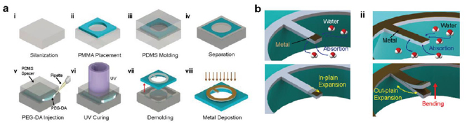
Figure 24. (a) Step by step fabrication processes; (b) conceptual schematic of the metal-coated hydrogel cantilever experiencing static deflection and resonance frequency shift upon absorption of water molecules [151]. John Wiley & Sons. © 2019 WILEY-VCH Verlag GmbH & Co. KGaA, Weinheim.
Download figure:
Standard image High-resolution image4.3. Organic/inorganic hybrid composites (polymer/ceramics)
Composites of polymeric materials with inorganic nanostructures have also been investigated and demonstrated to be utilized as sensing materials [152–154]. Nanostructured polymers have great potential for developing humidity sensors with low detection limits, fast response, enhanced stability, and high sensitivity due to their large surface-to-volume ratio [155].
Yoo et al [156] prepared a nanocomposite film where plasma-treated multiwall carbon nanotubes (CNT) were blended with polyimide (p-MWCNT/PI film). Therefore, the sensitivity of this polyimide-based resistive sensor was improved. An electrospinning approach has been carried out by Li et al [157], who obtained a composite of a silicon-containing polyelectrolyte polyethylene oxide and polyaniline. Vinyl-functionalized mesoporous silicas (SBA-15-vinyl) were chemically modified with hydrophilic sodium p-styrenesulfonate with free radical polymerization. This composite was then drop-coated on a ceramic substrate for humidity sensing [158]. Chappanda et al reported on the fabrication of highly sensitive humidity sensor based on composite thin films of metal-oxide frameworks and carbon nanotubes, in which the sensing films were fabricated on a QCM by spin-coating [159]. However, these polymers are normally coated by drop-casting or spin-coating, which are not suitable for cantilever-based sensors. Thus, fabrication of well-controlled organic/inorganic nanostructures on a microcantilever-based device still remained an interesting challenge and open question.
Recently, we reported on a fabrication method of composites of ZnO nanorod arrays and chitosan self-assembled monolayers (SAMs) on the top surface of a microcantilever [15]. Self-assembly is the autonomous organization of components into patterns and structures and possibly the most effective and versatile strategy for surface functionalization [160]. SAMs can be formed on semiconductor, conductor and dielectric surfaces, which leads to the formation of hierarchically complex structures with spatial correlations across multiple length scales [161]. SAM formation requires chemisorption on a surface followed by the spontaneous organization into 2D-crystalline long-range molecularly ordered domains [162, 163]. And as the component unit, the molecule normally has three functional groups: a head group, which is the end of the molecule binding to the substrate surface; a terminal group, which is the another end of the molecule and represents the out-functional surface of the SAMs; between them is the backbone of the molecule that is responsible for the molecular ordering normally being a unit of aliphatic chain or aromatic oligomer. In the case of chitosan molecules on ZnO nanorod surfaces, the hydroxyl (–OH) acts both as the head group to the ZnO surface and as the terminal group of the outer interface. D-glucosamine oligomers are in between as the backbone, where the ZnO-chitosan and chitosan-chitosan bonding is given by hydrogen bindings. Moreover, due to the extensive bonding of head groups to the ZnO nanorods surface via strong localized bonds and due to the partial in-plane cross-linking between adjacent molecules, chitosan SAMs on ZnO nanorods are prone to have a stable structure arrangement. In addition, since the head and terminal groups are identical, the chitosan SAMs give rise to multilayer structures, the layer thickness is decided by the self-assembling time [164].
5. Integrated microcantilever-based humidity sensors
As for humidity sensing, resistive humidity sensors and capacitive humidity sensors are currently the most widely used commercial humidity sensors, because of their advantages of easy fabrication, simple readout circuits (resistive humidity sensor) and low power consumption, wide temperature range and long term stability (capacitive humidity sensor), respectively. However, they are still some corresponding drawbacks that limit their applications, such as long recovery time and low stability for the former, complex readout circuits required for high precise detection for the latter [2, 3, 165, 166]. In addition, performances of both resistive and capacitive humidity sensors are directly affected by the electrical characteristics of the sensitive materials, which thus leads to nonlinear sensing responses at either low RH level (typically for a resistive sensor) or high humidity level (capacitive sensor) [2, 14, 167, 168].
5.1. Microcantilever-based humidity sensors
Microcantilever-based humidity sensors are attractive since they are capable of providing highly precise humidity sensing results despite their miniature dimensions. Microcantilevers have been used for humidity sensing by one-side coating with a water-absorbent layer, for example, gelatine or phosphoric acid, which react selectively with water molecules and thus causes a mass or surface stress change of the microcantilever, from which RH may then be determined [169, 170]. In 1995, Thundat et al reported that resonant AFM cantilevers with their surface modified by phosphoric acid or gelatine offered excellent potential for detecting water vapour, where both deflection and resonance frequency variations were used to monitor water exposure [145]. In addition, in the specific cases presented, a water-vapour adsorption amount corresponding to a picogram mass could be determined by recording the changes of resonance frequency using an AFM-based optical detection method. Shi et al demonstrated that a microcantilever (180 × 25 × 1 µm3) coated with an Al2O3 film could be used to monitor the environment, where moistures were controlled down to the parts-per-million (ppm) to billion (ppb) levels, by using a four-quadrant AFM head with an integrated laser and a PSD to detect the adsorption-induced deflection [127]. This indicated that microcantilevers have the potential to replace the current high-performance techniques to measure water-vapour contents including e.g. electrolytic cells and oscillating crystals, which have prices ranging from thousands to tens of thousands of US dollars. Recently, Toan et al proposed that a commercial AFM cantilever (130 × 30 × 3 µm3) patterned with silicon nanopillars by metal-assisted chemical etching process can be used for a moisture detection [128]. Here, the cantilever will be bent in the saturated state due to the surface tension of the condensed water layer, which let the pillars collapse together, and the bending was detected with a standard AFM-based optical-beam deflection technique. Compared with a cantilever with only a thin metal layer, which has a low modulation displacement of 50 nm, the cantilever with nanopillars on its top surface was found to have a much larger deflection of 700 nm, possibly because of not only absorption of water molecule occurred on the cantilever surface, but also a collapse of the pillars together due to the surface tension of the condensed water layer.
5.2. Static piezoresistive microcantilever-based humidity sensors
Although the optical detection-based microcantilever humidity sensors is very high sensitive and precise, the required detection system of an AFM is expensive and not portable and thus the potential applications are limited.
In piezoresistive humidity sensors, RH measurement is separated into humidity adsorption using a hygroscopic layer leading to a mass change of a resonator and mechanical-electrical transduction of the induced resonance-frequency shift using a piezoresistive strain gauge. Even though it is more difficult and complicated to fabricate, it is still possible to end up with complete sensors that include a cantilever, the readout system and control electronics on a single hybrid microchip. In 1999, Strembicke et al found that a magnetic-actuated piezoresistive cantilever-in-cantilever device was able to measure changes of RH by manually recording the resonant frequencies of the observed AC piezoresistance signal from an oscilloscope [171]. With a deposited MgF2 film, a readily measurable frequency shift of approximately 100 Hz was detected due to RH increasing from 5% to 90%. Lee and Lee proposed and introduced a piezoresistive microcantilever-based capacitive humidity sensor: a nitride-silicon microcantilever was suspended at a small distance above the glass substrate surface (with a stationary electrodes) as the moveable electrodes of a capacitor, the fixed glass substrate and the freestanding silicon wafer were originally bonded using a UV-sensitive glue [125]. Where a thin film of platinum and a spun-coated polyimide polymer film were respectively deposited as resistor and vapour detection layers. The moisture-dependent bending of the microcantilever induced by the variation in atmospheric humidity level changed the measurable capacitance between cantilever and substrate. The experimental results showed that the sensor has a high stability (< ±0.8%), a low hysteresis (1.9%RH) at high humidity (>65%RH). Besides, a high sensitivity (2.0 nF/%RH, at 25 °C) and a rapid response time (1.10 s, 20%RH–40%RH) were also reported [125]. And later, based on this design, Ma and Lee et al developed an integrated process for the fabrication of a Pt-resistor temperature detector using cantilevers covered with a polyimide layer for humidity, temperature and flow-rate detection. The sensing detection is obtained by measuring the changes in resistance caused by the beam deflection using an inductance-capacitance-resistance (LCR) meter (figure 25) [60]. The humidity sensitivities are 16.70 Ω %−1 at 40 °C, in which the hysteresis of 3.2%RH at low RH (<60%RH) were measured.
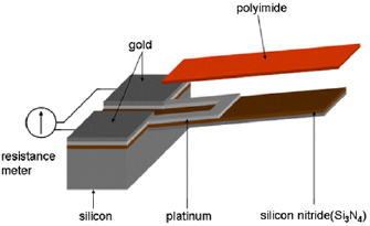
Figure 25. Schematic illustration of microcantilever-based sensor with Pt resistors and polyimide film [60]. 2008 © Springer-Verlag 2007. With permission of Springer.
Download figure:
Standard image High-resolution imagePiezoresistive microcantilevers (200 × 50 × 3.75 µm3) consisting of four structural layers of silicon nitride, polysilicon, silicon dioxide, and gold were designed by Sappat et al for humidity sensing [149], where the polysilicon layer acted as a piezoresistor. Twenty layers of poly(3,4ethylenedioxythiophene)/poly-styrene-sulfonic acid (PEDOT/PSS) were printed-patterned on the microcantilever using an inkjet-printing technique for the sensing layer. By measuring the resistance changes of the piezoresistive layer during humidity adsorbing and desorbing using a circuit bonded with the cantilever on a common printed circuit board, efficient water-vapour adsorption on the PEDOT/PSS layer was observed. Furthermore, compared with a commercial reference sensor, a linear high sensitivity from 22.3%RH to 66.3%RH and faster response and recover times were reported.
In 2015, Huang et al introduced their piezoresistive microcantilever for humidity detection, with a cantilever sensor being fabricated on n-type bulk silicon, ion-implanted p -type resistors as piezoresistors and a spun-on, patterned polyimide layer as the humidity-sensing material. TEOS (tetraethoxysilane)/SiN (silicon nitride) was deposited as dielectric layer stack between the piezoresistors and the sensing material, and the piezoresistive microcantilever (400 × 100 × 10.5 µm3) was released using an anisotropic dry-etching process (figure 26). The piezoresistive microcantilever was integrated in an IC circuit, hence the humidity could be determined directly from the measured Wheatstone-bridge output voltage. As reported in the paper, a sensitivity of 7 mV/%RH and a linearity of 1.9% were found at 20 °C, respectively, with a repeatability-uncertainty of 1.2%RH. The recovery time of the sensor at 25 °C was given to be 85 s [14].
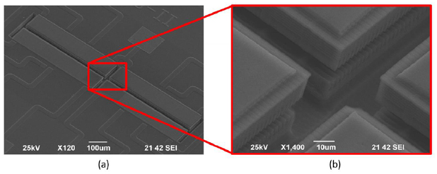
Figure 26. SEM image of the microcantilever piezoresistive humidity sensor: (a) front view of the micromachined structure; (b) detailed enlargement of the centre of the structure. Reproduced from [14]. CC BY 4.0.
Download figure:
Standard image High-resolution image5.3. Integrated resonant piezoresistive microcantilever humidity sensors
Recently, we reported a new piezoresistive microcantilever-based humidity sensor design (1000 × 170 × 15 µm3) that integrates a self-sensing element, a self-actuating element, and a self-reading element separately on the same microcantilever chip [15, 16]. ZnO nanorods (NRs) and chitosan self-assembled monolayers (SAMs) were selectively deposited on the microcantilever top surface as sensing materials. As shown in figure 27, a heating resistor and a full Wheatstone bridge were patterned at the clamped end of the microcantilever as the self-actuating and self-reading elements, respectively. Both heating and piezoresistors are p -diffused and fabricated by boron doping.

Figure 27. Schematic of a silicon piezoresistive microcantilever humidity sensor patterned with ZONRs. © 2018 IEEE. Reprinted, with permission, from [16].
Download figure:
Standard image High-resolution imageWhen driving a voltage composed of both DC and superimposed AC components to the heating resistor, the microcantilever will be excited into its fundamental resonant in-plane bending mode (details on the thermal actuation mechanism are given in section 2.1.3). Since the mass of water molecules adsorbed by the sensing layer depends on the environmental water vapour level, the relation between the cantilever resonance frequency (f 0) and the environmental RH level was determined under different RH levels. Here, resonance frequency was measured by a Labview-controlled multimeter [58] or monitored and recorded by home-made [54, 79] or commercial PLL circuits (MFLI Lock-in Amplifier, Zurich Instrument) [91] directly from the embedded piezoresistors.
Piezoresistive microcantilevers are first characterized in constant humidity and temperature environments using the 1-ω technique (see section 2.1.3), to check their stability and reliability. As shown in figure 28, resonance frequencies of a microcantilever coated with ZnO films/chitosan SAMs hybrids were measured from 30%RH to 70%RH at 25 °C, with a step of 10%RH, in a temperature- and humidity-level-controlled climate chamber. The resonance frequency was measured and recorded every second for 5 min at each RH condition, and small resonance frequency uncertainties under the different conditions were calculated to be 0.2 to 0.7 Hz, which correspond to RH deviations of 0.09%RH to 0.30%RH. In addition, uncertainties of 0.06%RH to 0.13%RH of piezoresistive microcantilevers with ZnO NRs and ZnO NRs/chitosan SAMs were found for over 90 min measurements [15]. These results prove that the proposed piezoresistive microcantilevers have good repeatability, indicating a good stability and reliability.
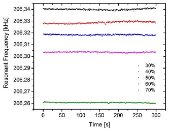
Figure 28. Short-time stability of microcantilevers coated with sputtering/annealing ZnO film (200 nm)/chitosan SAMs measured from 30%RH to 70%RH at 25 °C. Reproduced from [172]. CC BY 4.0.
Download figure:
Standard image High-resolution imageTo characterize the resonance mode shape of the microcantilevers under different environmental moisture levels, the fabricated sensors were measured from 30%RH to 70%RH in steps of 5%RH at 25 °C. As shown in figure 29, when the RH in the environment increases/decreases, the resonance signature shifts to lower/higher frequencies, corresponding to the equilibrium shift of the adsorption/desorption processes of the water molecules, which occurs between the environmental moisture and the deposited sensing material. By analysing the mode shapes and the resonance frequency shift upon humidity change, the RH sensitivity can be calculated.
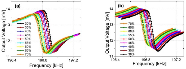
Figure 29. Frequency sweeps about f 0 of a piezoresistive microcantilever with 1.5 µm ZnO nanorods and chitosan SAMs at 25 °C under different RH levels ranging from 30%RH to 70%RH in both ascending (a) and descending (b) orders. Reprinted from [15], Copyright 2018, with permission from Elsevier.
Download figure:
Standard image High-resolution imageTo compare the influences of different sensing materials deposition on the piezoresistive microcantilever sensitivity, microcantilevers were coated with a ZnO thin planar film of 200 nm in thickness, a ZnO planar film (200 nm) and chitosan SAMs, ZnO NRs arrays of 1.5 µm and 6 µm in thickness, and ZnO NRs arrays (1.5 µm and 6 µm) and chitosan SAMs, respectively. A non-functionalized microcantilever was used as reference sensor. Then, the resonance responses of all sensors mentioned above were measured under different humidity conditions from 30%RH to 70%RH, and the corresponding resonance frequencies were calculated and depicted in figure 30. No obvious resonance frequency changes were observed with the non-functional microcantilever (~2 Hz) and the microcantilever with a 200 nm ZnO planar film (~5 Hz). However, for the microcantilever functionalized with ZnO NRs arrays or ZnO NRs arrays and chitosan SAMs, the sensitivities were significantly improved. Most notably is the microcantilever with 6 µm NRs/chitosan SAMs, its resonance frequency shift from 30%RH to 70%RH was more than 600 Hz, revealing a sensitivity improvement of ~300 times higher than the sensitivity of non-functional microcantilever and ~120 times higher than that of planar-film coated microcantilevers.

Figure 30. Resonant frequency shifts of blank microcantilevers, microcantilevers with sputtering/annealing ZnO film (200 nm), ZnO film/chitosan, ZnO NRs (1.5 µm), ZnO NRs (1.5 µm)/chitosan, ZnO NRs (6 µm), ZnO NRs (6 µm)/chitosan under different RH levels ranging from 30%RH to 70%RH at 25 °C. Reproduced from [172]. CC BY 4.0.
Download figure:
Standard image High-resolution imageIn addition, the Q values of microcantilevers were calculated from the mode shapes, where high Q is related to high resolution and sufficiency of the gravimetric microcantilever sensors. For example, as we can see from figure 31, the microcantilever with ZnO NRs (1.5 µm)/chitosan SAMs exhibited high Q values (~2000) in the humidity range between 30%RH and 70%RH, which is almost one magnitude higher than that (120–320) reported for a piezoelectric microcantilever-based humidity sensor [173].
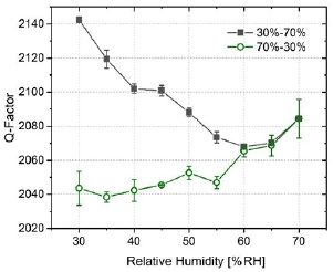
Figure 31. Quality factor (Q) values of the microcantilever with ZnO NRs (1.5 µm)/chitosan SAMs from 30%RH to 70%RH.
Download figure:
Standard image High-resolution imageFurthermore, this microchip has been proven possible to be integrated into an electric circuit. Hence, in our study, the fabricated microcantilevers were connected to a commercial PLL circuit to inspect their real-time response to the environmental moisture change. Bottles with different compounds and compounds saturated solutions that can supply different constant RH levels were used in this work, e.g. P2O5 (0%RH), CH3COOK (23%RH), K2CO3 (43%RH), NaCl (75%RH), K2SO4 (97%RH). Since the moisture concentration would change when the bottles were turn on and off, a state-of-the-art high-sensitive capacitive commercial humidity sensor [174] was used simultaneously during the whole measurement for reference. Signal acquisition time during recording of the capacitive commercial sensor and our developed piezoresistive sensors was one second, and the measurements started from 0%RH, and 10 min was given to each humidity level to arrive at a stable environment and signal read-out, as shown in figure 32. As we can see from the curves, both sensors exhibit very good responses to the moisture changes at low humidity levels from 0%RH to 43%RH. But when the sensors were measured in the high humidity levels (75%RH and 97%RH), unstable response and slight changes were observed from the measurements with the capacitive-commercial sensor, due to either longer time needed to response or poorer sensitivity at high humidity level, which is corresponding to the results reported in [2, 14, 167, 168]. However, our piezoresistive microcantilever-based humidity sensor showed a similar behaviour at high RH as in the low humidity level range, indicating that gravimetric humidity detection using piezoresistive microcantilever-based sensors provides a good repsonse in the entire range from 0%RH to 97%RH. In addition, the recovery of the commercial sensor from high to low humidity level is also slower than the response from low RH to high RH, while the piezoresistive microcantilever exhibits no apparent differences.

Figure 32. Online-measurement comparison of our piezoresistive microcantilever sensor using the 1-ω technique and a state-of-the-art capacitive commercial humidity sensor.
Download figure:
Standard image High-resolution imageTo test and investigate further the response and recovery time of our new-proposed piezoresistive microcantilever-based humidity sensing devices, the sensors were switched between two different moisture levels, for example, from the bottle with P2O5 to normal indoor atmospheric condition, and from atmospheric environment to a RH level of 84.3%. The results were recorded and depicted in figure 33. The response and recovery times were defined as the time needed to reach a stable status from low to high RH and from high to low RH, respectively, each defined as the time taken to reach 90% of the nominal humidity change. We found that the response time and recovery time of the 6.0 µm ZnO NRs-coated microcantilever were ~46 s and ~167 s, respectively. Meanwhile, for the microcantilevers coated with ZnO planar film, they were 11.9 ± 0.4 s and 12.0 ± 0.9 s, respectively, which were much faster than those of the used commercial sensor (i.e. 4 min).

Figure 33. Responses of a microcantilever with ZnO NRs (6 µm) when switching it between 0%RH and indoor atmospheric environment, and from atmospheric environment (~45%) to the RH level of 84.3%.
Download figure:
Standard image High-resolution image
In conclusion, piezoresistive microcantilevers were fabricated as complete sensors that include cantilever, actuation system, readout system, sensing materials and control electronics on a single hybrid microchip. This hybrid microchip can be used for completely RH range humidity sensing, with good repeatability, high resolution, high sensitivity, and fast response. Furthermore, piezoresistive microcantilevers have been proven to be a suitable platform for sensor integrated with on-chip electronic circuitry. Thus, it can work not only as the chip of a portable hygrometer, but can also be connected as a part of networks of the internet of things (IoT), to achieve real-time and remote high-sensitive moisture monitoring.
5.4. Comparison of resonant MEMS-based humidity sensors with other gravimetric sensors
To compare the various resonant gravimetric humidity sensors with their eigen frequencies ranging over orders of magnitude we define a sensitivity based on relative frequency shift instead of absolute values:

Papers of the state of art humidity sensors based on the resonant MEMS devices aforementioned in this chapter are collected and summarized in table 2.
Table 2. State of art resonant MEMS devices for gravimetric humidity sensing.
| Device | Resonator material | Resonance frequency | Sensitive material | Resonance frequency shift (Hz/%RH) | Sensitivity/range (ppm/%RH) | Response/recovery time | Hysteresis | Ref. |
|---|---|---|---|---|---|---|---|---|
| QCM | Quartz | 10 MHz | ZnO nano-needles | ~7–21.4 | ~0.7–2.14 (11.3–95.41%RH, RT) | 2–12/2–6 s | <2%RH/ | [26] |
| TiO2 nano-particles | 7.5 | 0.75 (0–20%RH, 24 °C) | 2/~4 min | <2%RH/ | [27] | |||
| PEDOT/PSS nanofibers | 86.92 | 8.692 (38–59%RH, RT) | N.G. | [29] | ||||
| GO/PEI film | 27.25 | ~2.7 (11.3–97.3%RH, RT) | 53 s/18 s | 0.54%RH | [28] | |||
| CMUT | Silicon | 50 MHz | Meso-porous silica film | 1.96 k | 39.2 (0–80%RH) | Very small hysteresis | [34] | |
| FBAR | ZnO/silicon | 1247 MHz | GO film | ~6.6 k | ~5.3 (3–83%RH, 18 °C–40 °C) | N.G. | N.G. | [35] |
| SAW | ST-quartz | ~433 MHz | MWCNT/nafion | ~0.4 M | ~924 (11–75%RH, 10 °C–23 °C) | <3/3 s | ⩽1%RH | [46] |
| ZnO/PI | ~132 MHz | ZnO film | ~3.5 k | ~27 (5–87%RH, RT) | 60–70 s | N.G. | [175] | |
| ZnO/glass | ~225 MHz | GO film | ~53 k | ~235.6 logarithmic (3–83%RH, 20 °C–50 °C) | 18/30 s | N.G. | [176] | |
| Electrostatic/capacitive | CMOS-MEMS | ~13.2 MHz | — | ~3.5 k | ~265 (15–85%RH, 35 °C) | N.G. | N.G. | [177] |
| External actuator/optical detection | Metal-hydrogel composite cantilever | ~14.1 kHz | Hydrogel | 9–12 | 640–850 (10–50%RH) | N.G. | N.G. | [150] |
| Integrated piezo | Silicon | 1.8 MHz | PMMA | ~0.35 k | 192 (10–50%RH, RT) | N.G. | N.G. | [178] |
| Piezoresistive microcantilever/electrothermal actuator | Silicon | 18–20 KHz | ZnO NRs (6 µm/chitosan SAMs | 3.35–15 | ~16.9–83.3 (30–80%RH, 25 °C) | 46 s/167 s | 14%RH | [15] and this work |
| 20.6 KHz | ZnO film/chitosan SAMs | ~2.4 | ~11.6 (30–80%RH, 25 °C) | 11–12 s/11–12 s | N.G. | This work | ||
| ~16.5 KHz | ZnO NRs (1.5 µm) films | ~0.72 | ~4.4 (30–80%RH, 25 °C) | N.G | 2.0%RH | [15] and this work | ||
Note: N.G. means not given.
As we can see from table 2, compared to the other type sensors, SAW-based humidity sensors show both very high resonance frequency shift and sensitivity to humidity changes. The resonance frequency shifts of piezoresistive microcantilever-based sensors are pretty small, however, their sensitivities are comparable to the QCM-, CMUT- and FBAR-based humidity sensors. The resonant MEMS devices show very fast response and recovery time from some seconds to few minutes, and the hysteresis are supposed to be determined by the deposited sensing materials. Thus, these resonant MEMS are potential platform or systems for humidity sensing in industry.
6. Conclusion and outlook
The paper has reviewed the developments and applications of humidity sensors and microcantilevers, the fabrication, actuation and detection of piezoresistive microcantilever- based humidity sensor are introduced in detail. Piezoresistive microcantilevers can be fabricated as complete sensors that include cantilever, actuation system, readout system, sensing materials and control electronics on a single hybrid microchip. The piezoresistive microcantilever-based humidity sensing is attractive because it is capable of providing high-sensitive humidity detection despite its diminutive size, a high sensitivity of 83 ppm/%RH can be achieved. Furthermore, by modifying the microcantilever structure or developing nanocantilever-based sensors, higher sensitivity can be expected. There are various actuation methods that can be used to excite the microcantilever, in which the self-actuation and self-read out can be realized. Thus, it can work not only as the chip of a portable humidity sensor, but also be connected as a part of networks of the IoT, to achieve the real-time and remote high-sensitive process moisture monitoring. Besides, piezoresistive microcantilevers are versatile microelectromechanical system (MEMS) that can be fabricated from a bulk silicon water by using the standard micromachining technique, and it is possible to accommodate sensors arrays on a single small chip. Thus, they have the potential for higher levels of integration with microelectronics at the die or package level, higher reliability, and lower failure rates. These advantages can lead to reduced cost and specialized circuits that can have enhanced performance and more functionality. Therefore, vapour detection using highly sensitive miniaturized silicon resonant sensors is of great interest for many applications, including consumer, industrial, and environmental applications. However, before piezoresistive microcantilever-based humidity sensors can be widely commercialized to replace the other already established humidity sensors, there remain some challenges to be completed, such as material limitations, temperature stability, packaging or batch integration with electronics.
Acknowledgments
J Xu, M Bertke, and H S Wasisto acknowledge support from the China Scholarship Council (CSC) under the Grant CSC No. 201506300019, 'Niedersächsisches Vorab', Germany, through the 'Quantum- and Nanometrology (QUANOMET)' initiative within the project of 'NP 2-2', and the Lower Saxony Ministry for Science and Culture (N-MWK) for 'LENA-OptoSense', respectively. The authors show their great thanks to the Royal Society of Chemistry, Molecular Diversity Preservation International and Multidisciplinary Digital Publishing Institute (MDPI), The Institute of Physics (IOP), ELSEVIER, Springer, The American Chemical Society (ACS) Publications, John Wiley and Sons and The Institute of Electrical and Electronics Engineers (IEEE) for their offering the republish-copyrights of the published figures.