

Abstract
Nozzleless jetting of droplets with different jetting angles is a crucial requirement for 2D and 3D printing/bioprinting applications, and Rayleigh mode surface acoustic waves (SAWs) could be a potential technique for achieving this purpose. Currently, it is critical to vary the jetting angles of liquid droplets induced by SAWs and control the liquid jet directions. Generally, the direction of the liquid jet induced by SAWs generated from a bulk piezoelectric substrate such as LiNbO3 is along the theoretical Rayleigh angle of ∼22°. In this study, we designed and manufactured thin-film SAW devices by depositing ZnO films on different substrates (including silicon and aluminium) to realize a wide range of jetting angles from ∼16° to 55° using propagating waves generated from one interdigital transducer. We then systematically investigated different factors affecting the jetting angles, including liquid properties, applied SAW power and SAW device resonant frequency. Finally, we proposed various methods using thin-film SAW devices together with different transducer designs for realizing a wide range of jetting angles within the 3D domain. A nozzleless jetting method is proposed using thin-film based surface acoustic wave devices to achieve a wide range of jetting angles for droplets.
Export citation and abstract BibTeX RIS

Original content from this work may be used under the terms of the Creative Commons Attribution 4.0 license. Any further distribution of this work must maintain attribution to the author(s) and the title of the work, journal citation and DOI.
1. Introduction
In the past few decades, acoustofluidics have attracted significant interests in the fields of microfluidics [1], biosensors [2, 3], and lab-on-a-chip [4], leading to its numerous potential applications in biomedical engineering, chemical engineering and medicine [5]. Among various acoustofluidic technologies, surface acoustic wave (SAW) based devices are one of the most commonly employed ones enabling droplet-based and microchannel-based microfluidics [6, 7]. Owing to their simple operations as sessile droplet-based devices, they have been demonstrated for various types of droplet manipulation applications such as mixing/streaming [8–10], transportation [11–13], jetting [14], nebulization [15], and heating [16]. Among these applications, droplet jetting plays an essential role in applications such as inkjet printing technology [17], needle-free fluid injection [18], single-molecule detection [19], and 3D printing [20].
Generally, jetting of liquid (in either a droplet format or in a liquid chamber) occurs at the liquid-gas interface when the inertial pressure generated by external energy sources overpowers the surface tension of the liquid. This has been well-documented in the literature based on the Navier–Stokes equation [21, 22]:
where  is velocity,
  is the gravitational acceleration vector,
  is pressure,
  and
and  are density and dynamic viscosity, respectively.
  is the surface tension force, and
  is a body force generated by the external energy source such as the SAW pressure. Initially, the applied external energy generates an internal recirculation inside the stationary droplet. A part of the transferred energy dissipates into the liquid due to its viscosity (second term of the right side of the equation). As a result of internal streaming, an internal pressure field is created within the droplet, which can deform the droplet. If the pressure at the liquid-gas interface is larger than the surface tension force, then the interface of the liquid would be deformed into a jet form and ejected from the surface [22].
A nozzle is usually required to generate adequate pressure to overcome the enormous surface tension of small liquid droplets [20]. Generation of significant shear stress can be realised using a nozzle in the fluid, thus leading to the formation of a jet [23]. However, this method has its limitations and can be detrimental to bioprinting applications. For example, cell mortality is increased, leading to clogging and significant degradation in performance [24].
To overcome these limitations, several approaches have been investigated for nozzleless droplet jetting, such as thermocavitation laser-generated bubble production [25] and spark-generated cavitation bubbles [26] inside the liquid. Compared with these methods, droplet jetting using the SAWs has many advantages such as high-energy efficiency, lower possibility of damage to biological entities in the liquid, and potential biocompatibility [23, 27]. Additionally, SAW-based droplet jetting could eliminate the needs for various mechanical components and nozzle, which makes the setup simpler and more reliable.
When SAWs reach the droplet located on its path, SAW energy is transferred into the liquid medium along the Rayleigh angle [28]:

where  and
and  are sound velocities in the liquid medium and on the piezoelectric substrate, respectively. This energy is capable of creating a large velocity field, which can deform the droplet, leading to the formation of a jet beam (see figure 1(a)), either using propagating SAW or standing wave SAWs [24, 29–31].
Table 2. The physical properties of the aqueous glycerol solutions used in experiments at 21 °C.
| Calculated Rayleigh angles | ||||||
|---|---|---|---|---|---|---|
| Glycerol volumetric fraction in solution (%) | Kinematic viscosity (× 10−6 m2 s−1) [41] | Density (Kg m−3) [42] | Sound velocity (m s−1) [41] | ZnO/Si (66.3 MHz) | ZnO/Al (40.4 MHz) | ZnO/Al (14.1 MHz) |
| 0 | 0.98282 | 997.83 | 1495 | 20.85 | 35.10 | 32.27 |
| 10 | 1.3121 | 1027.1 | 1537 | 21.47 | 36.24 | 33.29 |
| 14 | 1.4894 | 1038.9 | 1555 | 21.73 | 36.73 | 33.74 |
| 25 | 2.1941 | 1071.1 | 1601 | 22.41 | 38.01 | 34.87 |
| 50 | 7.03341 | 1141.4 | 1707 | 23.98 | 41.04 | 37.56 |
| 67 | 21.876 | 1185.4 | 1778 | 25.05 | 43.14 | 39.42 |
| 75 | 43.195 | 1204.9 | 1814 | 25.59 | 44.24 | 40.38 |
| 80 | 70.419 | 1216.7 | 1835 | 25.91 | 44.89 | 40.95 |
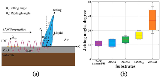
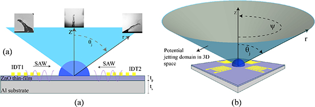
Figure 1. (a) A schematic illustration of SAW propagation on a ZnO/Si SAW device and droplet jetting. The SAW energy is transferred to the liquid medium by the Rayleigh angle, θR, which leads to droplet jetting along the jetting angle, θJ. (b) The summarized water droplet jetting angles for different SAW device structures from literature [13, 14, 22, 24, 32–34] and the results of ZnO/Al and part of the ZnO/Si SAW device results are from this study.
Download figure:
Standard image High-resolution imageGenerating liquid jets with tunable jetting angles has always been a challenge for applications such as 3D printing, cell dispensing and encapsulation, and 3D bioprinting. To overcome this challenge, it is essential to explore a wide range of jetting angles and control the jetting direction and speed. Based on equation (2), physical properties of solid surface and physicochemical properties of the liquid can influence the Rayleigh angle.
For bulk piezoelectric materials, changing the sound velocity on the substrate is difficult to realise, and as a result, the Rayleigh angle is nearly a constant. For example, 128° Y-X cut LiNbO3 SAW device has a SAW velocity of 3980 m s−1 on a given direction and thus the Rayleigh angle for water droplet located on this device (sound velocity 1495 m s−1 in water) is calculated to be a constant value of 23° [24, 35].
On the other hand, the jetting angle can be effectively modified by using thin-film piezoelectric materials on various substrates [35–37]. By changing types and thicknesses of both thin films and their substrates, the sound wave velocities in the solid surface, and thus the Rayleigh angles, can be significantly changed. In addition to being adaptable for Rayleigh angle tuning, thin-film based SAW devices have many advantages in terms of durability at high powers, flexibility, low cost, and less complexity in mass production and integration with electronic devices for sensing applications [18, 35, 36]. Thin-film SAW devices, e.g. those based on ZnO/Si and AlN/Si ones, do not have as large electromechanical coupling coefficients as their counterparts on bulk substrates. However, thin-film SAW devices do not exhibit the problems of bulk substrate ones such as in-plane anisotropic piezoelectric properties, inflexibility, brittleness, and difficulty to control/realize different wave modes [38].
To compare the jetting angles of different SAW devices, we have summarized the jetting angles obtained using thin-film (including ZnO/Si, ZnO/diamond/Si, and AlN/Si) SAW devices previously reported in literature [13, 14, 22, 24, 32–34], along with SAW devices made of bulk materials such as LiNbO3 [18, 39, 40] as shown in figure 1(b). The jetting angles can be varied significantly using thin-film devices on different substrates, for example, jetting angles can be reduced significantly using ZnO/Si, AlN/Si, or ZnO/diamond/Si SAW devices [37, 38]. Most studies on this topic have tended to focus on the droplet jetting effectiveness using various SAW devices, rather than achieving either the highest or lowest jetting angles. In principle, larger jetting angles can be realized using a substrate with a lower sound velocity or using liquids with a higher viscosity.
In this study, we explored various substrates (e.g. Al sheets with different thicknesses) together with viscous liquid to maximize the jetting angles and compared with those of ZnO/Si SAW devices, which can achieve the minimized jettingangles. Furthermore, we systematically analyzed the effects of different parameters such as substrate materials and thicknesses, droplet volume, liquid viscosity and density, wave frequency on the droplet jetting behaviour. We revealed that the jetting angle is not necessarily equal to the Rayleigh angle of the SAW device. Consequently, we define the jetting angle as the angle between the surface normal axis and the axis from the centre of the droplet on a solid surface to its tip, as shown in figure 1(a). Then, we showed that by applying different IDT patterns and electrode designs, including standing wave based IDTs, jetting angles could be varied in a significant wide range in a 3D space, which is useful for printing and bioprinting applications.
2. Experimental details
ZnO films with a thickness of ∼5 µm and film texture of (0002) were deposited on silicon wafers (Si thickness of 500 microns) and aluminium plates (with different thicknesses of 600 and 1500 microns, see table 1) using a direct current standard magnetron sputter system (Nordiko Ltd.) using a Zn target (99.99%), with DC power of 400 W and Ar/O2 mass flow ratio of 10/15. During the deposition, the chamber pressure was kept at ∼3 mTorr. The Cr/Au IDT with the thickness of 20/100 nm were fabricated onto the film-coated substrate using standard photolithography, magnetron sputtering and lift-off process. The bi-directional IDTs consist of 30 pairs of fingers with an aperture of 5 mm. The wavelengths of the IDTs were 64 and 200 µm. The resonant frequencies of the fabricated ZnO/Si and ZnO/Al devices were measured using an RF network analyzer (HP8752 A RF). The measured reflection spectra (S11) are presented in the supplementary figure S1 (available online at stacks.iop.org/JPhysD/53/355402/ mmedia).
Table 1. The measured frequencies and calculated velocities of ZnO/Al and ZnO/Si SAW devices. The Rayleigh angle is calculated for water droplets.
| SAW devices | Wavelength (µm) | Substrate thickness (µm) | Frequency (MHz) | Sound velocity (m s−1) | Rayleigh angle ° |
|---|---|---|---|---|---|
| ZnO/Si | 64 | 500 | 66.3 | 4200 | 20.66 |
| ZnO/Al | 64 | 600 | 40.4 | 2600 | 34.75 |
| ZnO/Al | 200 | 1500 | 14.1 | 2800 | 31.95 |
The surface of the SAW device was coated with CYTOP (∼200 nm thick, Asahi Glass Co.) to generate a hydrophobic surface. The measured static contact angles for a droplet on SAW devices were 114 °, and 122
 °for ZnO/Al and ZnO/Si deceives, respectively. To generate Rayleigh mode SAWs, an RF signal was generated by an RF generator (Macroni 2024) and amplified by a power amplifier (Amplifier research, 75A250). For all the cases, the applied power to the IDTs of SAW devices was measured using an RF power meter (Racal 9104). Droplets with different volumes from 2 µl to 40 µl were located on the SAW device using a micropipette, and their deformation, motion and jetting behaviours were recorded using a high-speed video camera (HotShot 1280CC) with a speed of 5000 FPS.
3. Results
3.1. Effect of substrates on jetting angles
The SAW velocity and frequency are mainly determined by the thin-film and substrate material. The measured values for the SAW frequencies and the corresponding sound velocities are listed in table 1. All the wave vibration modes were identified to be Rayleigh ones, which is mainly because of the smaller wavelength of the IDTs compared with the substrate thickness [18].
To explore effects of thin-film SAW structures (especially substrate and its thickness) on the jetting behaviour of the droplet, a set of experiments were conducted on three different SAW devices, with their parameters listed in table 1. All the experiments were performed using DI water droplets with a volume of 2 µl, and the applied SAW power was 60 W. Figure 2 shows the selected examples of jet formation in three different SAW devices. The obtained jetting angles for all the cases are the average values of the jetting angles within eight sequential snapshots after forming a jet beam and before complete liquid separation from the surface.
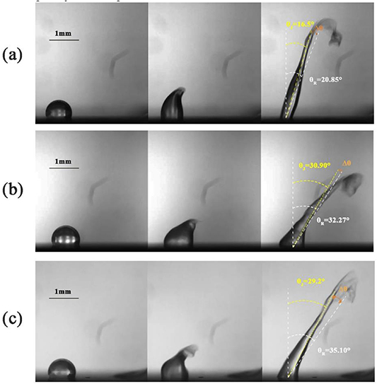
Figure 2. The snapshots of droplet jetting on different SAW devices. (a) ZnO/Si (66.3 MHz), (b) ZnO/Al (14.1 MHz), and (c) ZnO/Al (40.4 MHz). In all images, the DI water droplet has a volume of 2 µl and SAW with the power of 60 W is applied from the left side.
Download figure:
Standard image High-resolution image
Figure 3. The jetting images of 2 µl droplets with different aqueous glycerol solution. (a) ZnO/Al SAW device (14.1 MHz), (b) ZnO/Al SAW device (40.4 MHz), and (c) ZnO/Si (66.3 MHz) SAW device.
Download figure:
Standard image High-resolution imageAs can be seen from figure 2(a), the jetting angle for the ZnO/Si device is ∼16.5º whereas those of the ZnO/Al devices with frequencies of 40.4 MHz and 14.1 MHz are ∼29.2º and ∼30.9º, respectively (figures 2(b) and (c)). Results confirm that by using the aluminium substrate, the jetting angle can be significantly increased (see supplementary videos V1-V3 for the detailed phenomena).
There is a slight decrease in jetting angles when the wavelength is smaller for the ZnO/Al SAW devices. A plausible explanation can be the difference in the energy dissipated length along the surface that the SAW decays exponentially after reaching to the liquid medium. This attenuation length,  , is a factor of liquid properties and also SAW device structure and can be calculated by [32]:
where  and
and  are the solid and liquid densities, respectively, and
  is the SAW device resonant frequency. From equation (4), we know that for devices with a lower resonant frequency, i.e. 14.4 MHz, due to a higher attenuation length, most of the solid-liquid interface is excited by the SAWs. Therefore, the liquid droplet is directly excited by the transferred SAW momentum along the Rayleigh angle, and the droplet tends to form a jet along the Rayleigh angle direction. By increasing the SAW frequency, the attenuation length is decreased, and as a result, a smaller portion of the liquid medium at the solid-liquid interface is directly excited by the SAW. Accordingly, an internal recirculation field has been developed inside the liquid which tends to bend the jet direction toward the horizontal direction, thus could slightly increase the jetting angle.
Figure 4(a) summarizes data of the jetting angles as a function of liquid kinematic viscosity at various applied SAW powers, and also the velocity data of the top of the jet obtained from a ZnO/Al SAW device with a frequency of 14.1 MHz. It clearly shows that by increasing the liquid viscosity, the jetting angle tends to increase, and the jet velocity is decreased. It also turns out that at higher viscosities, the behaviour of the droplets is gradually changed from jetting to angled jumping with large deformation, followed by pumping.
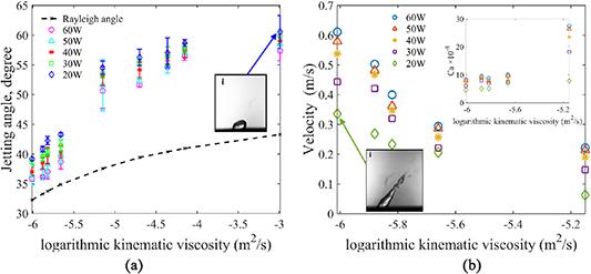
Figure 4. (a) The jetting angle as a function of kinematic viscosity of the liquid and applied SAW powers. The error bars represent the standard error of four experiments. (b) The average jet velocity versus kinematic viscosity of the liquid for five different applied SAW powers. The results of both graphs are for a 2 µl droplet sessile on a 14.1 MHz ZnO/Al SAW device.
Download figure:
Standard image High-resolution imageThe maximum jetting angle with the DI water can be as large as 39°, and this value can be increased up to 55º by increasing the kinematic viscosity. This jetting angle is the maximum angle realized using propagating SAW driven from one IDT, up to date reported in the literature. The direction of the droplet jet is functions of the internal recirculation field, viscous dissipation and radiation pressure created by the leakage of the SAW [43]. In liquids with further higher viscous dissipations, pressure field at the air-liquid interface will not be large enough to overcome the surface tension force for creating the jetting.
To have a better insight into the effect of viscosity on the jetting angle, we summarized the data of average jet velocity versus glycerol volumetric fractions for different applied SAW powers and the results are shown in figure 4(b). The jet velocity was calculated based on two-component velocity method in x and z directions. The obtained data of jetting velocity for all the cases are the average velocity values of the tip of the jet beams within eight sequential snapshots after forming a jet beam and before complete liquid separation from the surface. As expected, with the increase in liquid viscosity, the average jet velocity is decreased. Additionally, the relationship between dimensionless velocity and capillary number can be written using the following equation [44]:
where  is liquid dynamic viscosity, U is average jet velocity, and
  is surface tension coefficient. Figure 4(b) shows that by increasing the viscosity, effect of viscous dissipation becomes more significant than surface tension in controlling the shape and angle of the jetting beams. The jetting angles and velocity results for the 40.4 MHz ZnO/Al device and 66.3 MHz, ZnO/Si device, are presented in supplementary figure S2.
To illustrate the effect of applied SAW power on the jetting behaviour of the droplet, we conducted a set of experiments using a 2 µl droplet with five different viscosities. The time evolution of a droplet on the ZnO/Si device with a resonant frequency of 66.3 MHz is presented in figure 5.
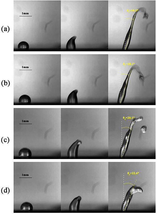
Figure 5. Snapshots of DI water droplet jetting by different applied SAW powers. The applied SAW powers to the ZnO/Si SAW device with a resonant frequency of 66.3 MHz are: (a) 60 W, (b) 50 W, (c) 40 W, (d) 30 W. The volume of the DI water for all the cases is kept constant at 2 µl.
Download figure:
Standard image High-resolution imageIt can be observed that at higher applied powers, the droplet is separated from the surface as a long cylindrical beam; however, at lower powers, the length of the beam is relatively shorter. Due to Plateau–Rayleigh instabilities [22], at higher power cases, the jet is eventually broken up into droplets as seen in the last snapshot of figure 5(c).
3.2. Effect of droplet volume
Figure 6 shows droplet jetting snapshots for five different droplet volumes on ZnO/Si SAW device with a frequency of 66.3 MHz. The results clearly show that by increasing the droplet volume, the jetting angle is slightly increased. To explain this phenomenon associated with the droplet deformation and jetting by SAW, we consider the relationship among viscous dissipation, applied SAW force, gravitational force, and surface tension force. For the cases with volumes smaller than 8 µl, the shape of the droplet is a long and thin beam, due to the large portion of transferred SAW energy over the gravitational energy. By increasing the droplet volume, due to the increased effect of gravitational energy [45] of the droplet, the jet is bent toward the horizontal direction during the jet formation which leads to a higher jetting angle (see supplementary video V-6). The droplet jetting angle is plotted versus droplet volume for three different solutions with different viscosities in figure 7(a). As expected, by increasing the droplet volume, the difference between the Rayleigh angle and the jetting angle becomes increased. To have a better understanding of the effects of droplet volume on jetting behaviour, the average jet velocity versus droplet volume is illustrated in figure 7(b). By increasing the droplet volume, the ratio of the droplet inertia and applied SAW energy is sharply increased. Consequently, the average jet velocity is decreased exponentially. A lower jetting velocity leads to a higher jetting angle at a larger droplet volume.
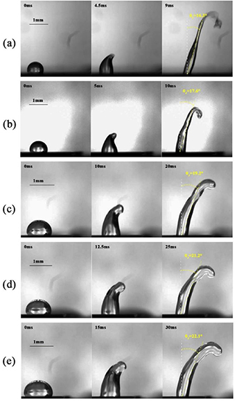
Figure 6. Snapshots of DI water droplet jetting with different volumes on a ZnO/Si SAW device with a resonant frequency of 66.3 MHz. The droplet volumes are: (a) 2 µl, (b) 8 µl, (c) 20 µl, (d) 30 µl, (e) 40 µl. For all the cases, the applied SAW power is 60 W, and the wave is propagating from left to right.
Download figure:
Standard image High-resolution image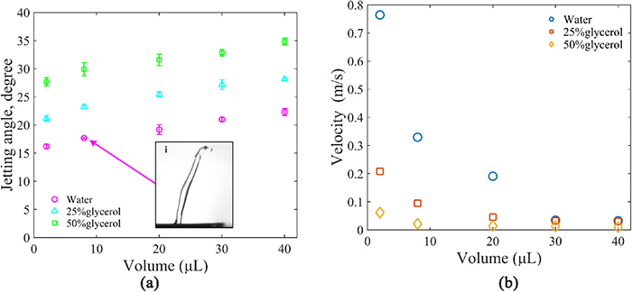
Figure 7. (a) The jetting angle versus droplet volume on 66.3 MHz ZnO/Si SAW device with different liquids. (b) The average jet velocity as a function of droplet volume. All the results are presented for 66.3 MHz ZnO/Si SAW device. Error bars represent the standard error of four experiments.
Download figure:
Standard image High-resolution image4. Discussion
4.1. Achieving highest and lowest jetting angles
The present results show that using thin-film SAW devices, a wide range of jetting angles can be readily achieved. The key idea is to design the thin-film based SAW device on different substrates which have different sound velocities. Here we reported a jetting angle in the range of 29º up to 40º for pure water droplets using the SAW devices which were made by substrates. Furthermore, by increasing the kinematic viscosity of the liquid, we realized the maximum jetting angle up to 55º for a 50% aqueous glycerol solution.
As qualitatively predicted by the Rayleigh equation (see equation (1)), by increasing the SAW propagation velocity on the solid substrate, the Rayleigh angle can be significantly reduced and theoretically the jetting angle is minimized. For instance, the sound velocity on AlN/diamond/Si substrate is as large as ∼10 320 m s−1 [46]. Thus, by fabricating SAW devices on this substrate, Rayleigh angles as low as ∼8º is achievable.
Another approach to achieve a low jetting angle is to use the different modes of the waves on the same SAW device. For example, by applying a high-frequency Sezawa wave mode on the ZnO/Si device (or in other cases, higher harmonic modes in many different SAW devices), a smaller jetting angle can be achieved compared to the fundamental Rayleigh SAW mode on the same device due to their higher wave propagation velocities [47] (see supplementary figure 4).
On the other hand, based on the theoretical prediction from equation (2), the Rayleigh angles from the ZnO/polymer SAW devices should be much larger than those of ZnO/Al SAW devices, as the sound velocities in many polymers are much lower compared to aluminium substrates [48]. For example, in theory, jetting angles at about 90° is possible based on equation (1). However, the reality is that most polymers are too soft and have low moduli, and droplet transportation and jetting cannot be effectively realized on those polymer substrates due to significant SAW energy dissipation into polymer substrates. So far, we have not managed to achieve any practical phenomena droplet transportation or droplet jetting on various ZnO/polymer SAW devices.
4.2. 2D and 3D jetting design by a pair of facing IDTs
Changes of jetting angles can be further realized by using SAW devices with a pair of facing IDTs. The ranges of jetting angle in a 2D domain are illustrated in figure 8(a) using a polar coordination system. In this system, the position of the jet tip, r, and the jetting angle,  , can be modified by changing the all parameters discussed in the previous sections. We can also change the direction of the jetting by switching from one of the IDTs to the other one. Based on the results we have obtained in this study, we can expect that the jetting angle of
  can be modified in a range of −55º to 55º, simply by using two pairs of IDTs of ZnO/Al SAW device, as shown in figure 8(a). Vertical jetting, e.g. jetting angle of 0, is easily obtained by applying standing SAWs generated by two SAWs from two sides with the same power simultaneously (see supplementary video V-7).
Figure 8. (a) Droplet jetting with a pair off facing IDTs in the 2D domain. (b) The maximum range of droplet jetting angle in 3D space with a 4 IDT SAW device (layer thicknesses are not to the scale).
Download figure:
Standard image High-resolution image
Further increase of the jetting angles can be achieved by applying two unequal counterpropagating SAWs or by applying two equal SAWs but with unequal time durations, which have been reported by Connacher et al [49]. The idea behind this phenomenon, which can generate jetting angles up to 55° on a LiNbO3 SAW devices, is that the acoustic energy transferred to the liquid medium from each side is a function of the product of applied SAW power and duration. By changing the ratio of the applied powers from two sides of the IDTs and also their duration ratios, a controllable range of the jetting angle is effectively achieved. This good idea [49] can expand the droplet jetting applications, simply using the conventional SAW devices on the bulk LiNbO3 substrate.
We further propose that by using a SAW device with two pairs of straight IDTs structured in a rectangular shape (see figure 8(b)), a conical domain of variable jetting angles can be effectively achieved in a 3D space. In this setup, not only the jetting angle can be modified, but also the rotation angle, Ψ, can be altered and controlled by changing the ratio of the power applied to each IDT.
For instance, by modifying the applied power ratio to two neighbours IDTs, e.g. two adjacent and vertically aligned IDTs, the inclined jetting angles can be controlled. By further changing the ratio of the applied power from two sides and duration ratios into each IDT, a controllable range for the jetting angle in the 3D domain could be effectively achievable.
5. Conclusion
In summary, this study showed that the jetting angles could be significantly changed from 16° to 55º, simply using a thin-film SAW device on various substrates. We showed that by changing the microfluidic parameters such as liquid viscosity or density, regardless of the SAW device design, the jetting angle of the droplet could be further altered. For example, the jetting angle can be increased either by using a substrate with lower sound velocity material and smaller thickness or using liquids with higher viscosity and vice versa. Alternatively, to slightly change the jetting angle, the applied SAW power and droplet volume could be increased (or decreased); to obtain a higher (or lower) jetting angle. These parameters offer a design space to obtain varying jetting angles. Based on the research outcomes, the present findings could have a potential application in 3D printing and bioprinting applications.
Acknowledgments
This work was supported by the Research and Development Program of China (Grant No. 2016YFB0402705), 'Zhejiang Provincial Natural Science Foundation of China (LZ19E050002)' and the 'National Natural Science Foundation of China (51875521, 51605485 and 51575487)', Engineering Physics and Science Research Council of UK (EPSRC EP/P018998/1) and UK Fluidic Network (EP/N032861/1)—Special Interest Group of Acoustofluidics, and Newton Mobility Grant (IE161019) through Royal Society and NFSC. Shenzhen Key Lab Fund (ZDSYS20170228105421966), Shenzhen Science & Technology Project (Grant No. JCYJ20170817100658231).