

Abstract
For flexible strain sensors, unmodified polymer substrates often have unsatisfactory performances. Herein, we report a biomimetic petal patterned polydimethylsiloxane strain sensor comprising Ir nanoparticles-modified multi-walled carbon nanotubes. Under optimal processing, the modified flexible strain sensor exhibits better comprehensive performances, such as sensitivity up to 20.33, sensing range of 0%–35%, response time of 242 ms, and more than 9000 cycles of repeated stretch–release. Moreover, it can be used for monitoring human pulse, wrist motion, and phonation. Such a facile and friendly flexible strain sensor will bring great potentials in wearable devices, human motion detection, and soft robotics.
Export citation and abstract BibTeX RIS
1. Introduction
In recent years, flexible strain sensors are receiving tremendous attention in the fields of wearable devices, electronic skin, human-computer interaction, health monitoring, flexible display, etc [1–8]. Generally resistance-type flexible strain sensor is composed of conductive network and flexible polymer substrate [9–11]. Compared with the capacitance-type, it has a considerable range of resistance value changes with higher sensitivity and simpler fabrication processing, so it is more widely used [11–13].
In order to obtain better applications in wearable devices, flexible strain sensors must have higher sensitivity, stretchability, and cyclic durability [14]. Among them, the sensitivity is one of the most important parameters, which is defined by the gauge factor GF = (ΔR/R0)/ , in which ΔR/R0 refers to relative resistance change and of tensile strain [14, 15]. In other words, the slope of the change of the relative resistance to the strain curve can be used to describe the sensor's ability to detect subtle deformation [14, 16, 17]. For the construction of flexible strain sensor, the flexible substrate and conductive filler should have reliable quality, good stretchability, and simple fabrication process. At present, the commonly used flexible substrate materials mainly include polydimethylsiloxane (PDMS), ecoflex, dragon skin, polyaniline, polypyrrole, polythiophene, rubber, etc [14, 18–24]. PDMS is one of the most promising flexible substrates because of its excellent bio-compatibility and elasticity [25]. Many studies have reported that the patterned PDMS substrate has high flexibility, better sensitivity, outstanding durability and fast response/recovery speed [26–28]. Bionics is an important and effective method to build technical system by imitating the function and behavior of biological system. The epidermis of some plants has abundant microstructures with proper response to the environment. Hünig et al found that the micro-protrusion arrays of rose petal surface, with a height of the petal-patterned
∼19 ± 3 μm and a diameter of ∼32 ± 3 μm at the bottom, has a better enhancement effect on light absorption for thin film solar cells [29]. Therefore, if the microstructure of petals is transferred to PDMS, maybe it also helps to improve the strain sensor's performance.
, in which ΔR/R0 refers to relative resistance change and of tensile strain [14, 15]. In other words, the slope of the change of the relative resistance to the strain curve can be used to describe the sensor's ability to detect subtle deformation [14, 16, 17]. For the construction of flexible strain sensor, the flexible substrate and conductive filler should have reliable quality, good stretchability, and simple fabrication process. At present, the commonly used flexible substrate materials mainly include polydimethylsiloxane (PDMS), ecoflex, dragon skin, polyaniline, polypyrrole, polythiophene, rubber, etc [14, 18–24]. PDMS is one of the most promising flexible substrates because of its excellent bio-compatibility and elasticity [25]. Many studies have reported that the patterned PDMS substrate has high flexibility, better sensitivity, outstanding durability and fast response/recovery speed [26–28]. Bionics is an important and effective method to build technical system by imitating the function and behavior of biological system. The epidermis of some plants has abundant microstructures with proper response to the environment. Hünig et al found that the micro-protrusion arrays of rose petal surface, with a height of the petal-patterned
∼19 ± 3 μm and a diameter of ∼32 ± 3 μm at the bottom, has a better enhancement effect on light absorption for thin film solar cells [29]. Therefore, if the microstructure of petals is transferred to PDMS, maybe it also helps to improve the strain sensor's performance.
In order to ameliorate the sensitivity of flexible sensor, the proper conductive fillers, as the sensing materials, are crucial and necessary [6], such as carbon black, carbon nanotubes (CNTs), graphene, nanowires, and nanoparticles (NPs) [13]. Among them, CNTs are favorable due to their remarkable stiffness and strength [30, 31]. Amjadi et al reported a CNTs-silicon rubber strain sensor with a stretchability of 500% [32]. However, the introduction of CNTs in the sensor leads to low sensitivity and high hysteresis [33]. On the contrary, the sensitivity of flexible strain sensor modified by metal NPs is higher [34]. Puyoo et al prepared a Pt NPs-based strain sensor with a sensitivity of 70 at a strain level of 0.5% [35]. Therefore, the better comprehensive performances of the flexible strain sensor may be achieved by combination of metal NPs decorated CNTs [36].
In this work, we designed and fabricated a biomimetic petal patterned PDMS strain sensor comprising Ir NPs-modified multi-walled CNTs. Ir NPs with various cycles were prepared by atomic layer deposition (ALD). Under optimal processing condition, the modified flexible strain sensor based on the petal patterned PDMS with 200 ALD cycles-Ir NPs-decorated CNTs exhibits better comprehensive performances.
2. Experimental section
2.1. Fabrication of the flexible strain sensor
First the petal-patterned PDMS was fabricated. The liquid dimethylsiloxane monomer (DMS, silicone oil) and crosslinker (Dow Corning Sylgard 184) were mixed at a mass ratio of 10:1 by magnetic stirring for 30 min. Then the mixture was deflated in vacuum for 30 min to remove the bubbles, poured onto the rose petal attached to the glass slide and cured at 75 °C for 1 h. When the cured PDMS film was carefully peeled from the rose petal surface, the microstructures of the rose petal surface were copied to the surface of the PDMS film.
Subsequently, the sensing materials of Ir NPs modified CNTs were deposited by ALD. Hydroxy-treated CNT powders were purchased commercially. Thermal ALD (Picosun SUNALETMR-150B, Finland) was used to prepare Ir NPs on CNTs at 300 °C using iridium acetylacetonate (Ir(acac)3, 200 °C) and oxygen with a cycle sequence of 8 s Ir(acac)3 dose, 20 s N2 purge pulse, 8 s O2 dose, and 20 s N2 purge pulse [36]. In order to investigate the effect of the density of Ir NPs on the performance of flexible strain sensor, 100, 200 and 300-cycle Ir NPs were deposited on CNTs.
Figures 1(a)–(h) illustrates the fabrication flow chart of petal patterned PDMS based flexible sensor comprising CNTs decorated with Ir NPs. In figure 1(a), a rose petal washed with deionized water was first fixed on a clean and smooth glass slide using adhesive tape as template. The deflated PDMS liquid was poured on the petal surface in figure 1(b). Then the PDMS film was peeled off from the rose petal (figure 1(c)). At the same time, the ALD-derived Ir NPs were loaded on the CNTs, as shown in figures 1(d) and (e). Then, the Ir NPs-modified CNT powders (Ir NPs@CNTs) were ultrasonically dispersed in ethanol (figure 1(f)). In figure 1(g), Ir NPs@CNTs were drop-casted on the above PDMS film. Finally, the Cu electrode was assembled at two sides of the patterned PDMS, and a PDMS film was covered on the sensor surface as the protective layer, as seen in figure 1(h). The flexible strain sensor was prepared successfully.
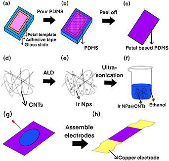
Figure 1. Fabrication flow chart of petal patterned PDMS based flexible sensor comprising CNTs decorated with Ir NPs.
Download figure:
Standard image High-resolution image2.2. Characterization
The morphology and microstructure of the strain sensors were recorded by optical microscopy, scanning electron microscopy (SEM, Zeiss ultra55, Carl), and transmission electron microscopy (TEM, Tecnai G2F20 S-Twin, FEI). The stretching and bending strain were applied on strain sensor using a programmable motor-controlled stepper (Beijing Optical Century Instrument Corp.). All electrical measurements were carried out at room temperature by means of CHI600E electrochemical workstation (Shanghai Chenhua Instrument Corp.).
3. Results and discussion
3.1. Strain sensing performance
The morphology of petal patterned PDMS film and rose petal was characterized by optical microscope and SEM. Figure 2(a) is an optical micrograph of rose petals. It can be observed that the surface of rose petals consists of ordered micro-protrusion arrays. Every micro-protrusion is close to hexagon at the bottom with distance of opposite sides of ∼34.22 μm and circle at the top with diameter of ∼15.32 μm. Each protrusion is separated by a ∼9.75 μm wide channel. SEM images of petal patterned PDMS with different magnifications are shown in figures 2(b) and (c). There exist micro-pits on the surface of petal patterned PDMS film. Each micro-pit is approximately hexagonal at the top with distance of opposite sides of ∼33.85 μm and round at the bottom with diameter of ∼13.08 μm. The microstructure of petal patterned PDMS surface is an inverse structure of rose petal surface with similar sizes, indicating that the microstructure of rose petal surface has been copied to the petal patterned PDMS surface successfully. Figure 2(d) displays a SEM image of petal patterned PDMS film coated with CNTs. A continuous CNTs conductive network is formed on the PDMS surface by the drop coating method, including the side wall and bottom of the 15.25 μm micro-pit, which are completely covered with CNTs (the inset of figure 2(d)).
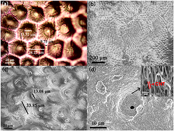
Figure 2. (a) Optical micrographs of rose petals. (b), (c) SEM images of petal patterned PDMS films at different magnifications. (d) SEM images of petal patterned PDMS films decorated with CNTs.
Download figure:
Standard image High-resolution imageALD-derived Ir NPs with various cycles were used to decorate the CNTs so as to adjust the sensitivity of petal patterned PDMS flexible strain sensors. Figure 3(a) shows TEM and high-resolution TEM (HRTEM) images of Ir NPs@CNTs after 200 ALD cycles. It is found that Ir NPs have similar particle sizes of average ∼12 nm with relatively uniform distribution on the out wall of the CNTs in diameter of ∼25 nm. The lattice fringes from Ir (111) with a spacing of about 0.229 nm and from multi-walled CNT (002) with a spacing of about 0.339 nm can be clearly observed, suggesting Ir NPs@CNTs nanocomposite system has been obtained successfully.
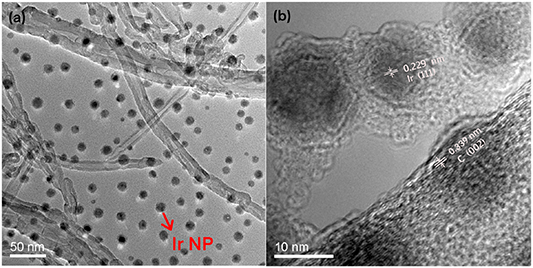
Figure 3. (a) TEM and (b) HRTEM images of 200-cycle Ir NPs@CNTs.
Download figure:
Standard image High-resolution imageThe effect of the density of Ir NPs (100, 200 and 300 ALD cycles) on the sensitivity of Ir NPs@CNTs composites has been studied, as illustrated in figure 4. The sensitivity of each sample can be calculated from the slope of ΔR/R0- curves. Two reference samples are CNTs based flat and petal patterned PDMS films. Table 1 summarizes the sensitivities and sensing ranges of strain sensors of various Ir NPs@CNTs patterned PDMS films and two control samples.
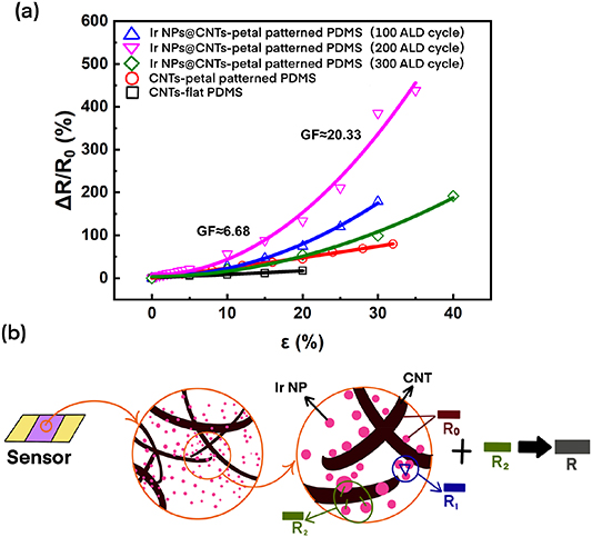
Figure 4. (a) Relative resistance change dependence on applied strains for strain sensors of various Ir NPs@CNTs petal patterned PDMS films and two control samples. (b) Schematic model of the Ir NPs@CNTs petal patterned PDMS films.
Download figure:
Standard image High-resolution imageTable 1. Sensitivities and sensing range of strain sensors of various Ir NPs@CNTs petal patterned PDMS films and two control samples.
| PDMS Substrates | Sensing materials | Sensitivity (0%–20%) | Sensitivity (20%–40%) | Sensing range |
|---|---|---|---|---|
| Flat | CNTs | 0.81 | − | 20% |
| Patterned | CNTs | 2.48 | 2.48 | 32% |
| Patterned | 100-cycle Ir@CNTs | 3.72 | 10.47 | 30% |
| Patterned | 200-cycle Ir@CNTs | 6.68 | 20.33 | 35% |
| Patterned | 300-cycle Ir@CNTs | 3.30 | 9.28 | 40% |
The sensitivity of CNTs-flat PDMS sample without surface microstructure is about 0.81 with the sensing range of 0%–20%. After introducing the petal patterns in PDMS film, the sensitivity and sensing range of CNTs-petal patterned PDMS sample increase to 2.48 and 0%–32%, respectively. And the Ir NPs modification on CNTs has a positive role on the flexible strain sensor with enhanced sensitivity, especially in larger stretchability ( ≥ 20%). Using petal patterned PDMS films as substrates, strain sensors based on Ir@CNTs with different ALD Ir cycles are compared. 200-cycle Ir NPs@CNTs patterned PDMS exhibit best sensitivity of 6.68 at 0%–20% strain and 20.33 at 20%–35% strain, which might be attributed to the proper size and density of 200-cycle Ir NPs on CNTs (figure 3).
Moreover, two control samples without Ir NPs modification show a linear relationship in ΔR/R0- curves, however strain sensors of 100, 200, 300-cycle Ir NPs@CNTs petal patterned PDMS have a nonlinear exponential relationship in ΔR/R0- curves, especially for 200-cycle Ir NPs@CNTs petal patterned PDMS. For the former, CNTs under strain have no change in the conduction mechanism, so the electrical response to strain is linear. For the latter, the introduction of Ir NPs makes the resistance of the conductive network partially dependent on the tunneling resistance between metal NPs and between metal NPs/CNTs. And the tunneling resistance is exponentially dependent on the distance between metal NPs and between metal NPs/CNTs [37], therefore flexible strain sensors of Ir NPs@CNTs patterned PDMS can possess higher sensitivity under larger strain.
Some researchers have proposed mathematical models to predict the change of relative resistance of composite containing conductive NPs according to the tunneling theory [37, 38]. It is found that the conductive NP size, the separation gap between NPs, and the conductance of cross-linked NPs have significant influence on the sensor's sensitivity [37]. In order to better understand the sensing mechanism of our flexible strain sensors, a simple schematic model has been illustrated in figure 4(b). The conductive network of the sensor is composed of Ir NPs-modified CNTs and dispersive Ir NPs on PDMS, as indicated in figure 3(a). The resistance of the conductive network could be defined as follows: R = R0 + ΔR, where R is the total resistance of the conductive network, R0 of the resistance of the nanocomposite itself, and ΔR is the connection resistance between nanocomposites [18, 39]. The R0 is basically constant, but the ΔR = R1 + R2, which varies with deformation. Herein, R1 is the resistance between Ir NPs in nanocomposites and R2 is the resistance between Ir NPs and CNTs. When the conductive network is stretched, the distance between Ir NPs and between Ir NPs and CNTs will become large, resulting in the evident increase of R1 and R2. Especially under large strain, the exponentially enhanced junction resistance ΔR due to the tunneling effect is beneficial to obtaining high gauge factor. Meanwhile, the dispersive Ir NPs also increase the connection probability of different CNTs after releasing the strain, improving the stability and repeatability of the sensor [39].
Above all, the flexible strain sensor of 200-cycle Ir NPs@CNTs and petal patterned PDMS film exhibits optimal performances. Its maximum gauge factor is about 20.33, which is about 7.2 times more than the sensor based on CNTs and petal patterned PDMS film, and is about 24.1 times more than the sensor based on CNTs and flat PDMS film. Therefore, the following dynamic response, response and recovery time, repeatability and stability, hysteresis, and human-motion detection were examined carefully using the flexible strain sensor of 200-cycle Ir NPs@CNTs petal patterned PDMS sample.
Figure 5(a) shows the dynamic response of flexible strain sensor under different tensile strains. As the tensile strain increases from 0 to 35%, the ΔR/R0 of the sensor also increases gradually. Figure 5(b) is an enlarged view of figure 5(a) for the strain of 0%–10%. It can be observed that the sensor has a fast response to each tensile strain with stable change value of the relative resistance. When the tensile strain is removed, the sensor can also return to the initial '0' value quickly. When the strain exceeds 35%, the sensor breaks at the connections of electrodes/PDMS due to the mismatch of Young's moduli between them. The dynamic response of sensor under various compressive strains is recorded in figure 5(c). The response to the compressive strain of 0%–8% is rapid and stable with the sensitivity of about 6.11. Figure 5(d) displays the response and recovery time curves of flexible strain sensor. When a 10% tensile strain is applied to the sensor, the response time of the sensor is about 186 ms.

Figure 5. Performance of flexible strain sensor of 200-cycle Ir NPs@CNTs petal patterned PDMS film. (a) Relationship between the relative resistance change and time under different tensile strains. (b) An enlarged view of figure 5(a) from 0%–10% strain. (c) Relationship between the relative resistance change and time under different compressive strains. (d) Response and recovery time curves. (e) Repeatability test under tensile strain of 4%. (f) Stability test under tensile strain of 10% and 20%. (g) Hysteresis curve under tensile strain of 35%.
Download figure:
Standard image High-resolution imageWhen the applied strain is withdrawn, the sensor immediately returns to the initial state without obvious hysteresis with the recovery time of about 242 ms. The repeatability and stability tests of the sensor were also carried out. In figure 5(e), a 4% tensile strain is exerted to the sensor and then removed for ten times, it can be seen that the response shapes of I-t curve show better repeatability except the first cycle. In figure 5(f), a tensile strain of 10% is first exerted on the sensor and then a strain of 20% is applied after 0.5 s, which is taken as a stretch and release cycle. The experimental results indicate that the current value of the sensor increases from 5.27 × 10⁻⁶A to 5.79 × 10⁻⁶A after 9000 cycles. The current drift is less than 10%, suggesting the excellent stability of the sensor during the long service. Figure 5(g) exhibits the relative resistance changes of the sensor during the stretch and release. The sensor shows limited hysteresis (<10%) at 20%–35% strain and less hysteresis (<4%) at 0%–20% strain, moreover the resistance of the sensor can return to its initial value after complete release. This can be ascribed to the fact that 0D Ir NPs are hard to be damaged in nanocomposites under large strain, different from easily destroyed 1D CNTs. Above all, 200-cycle Ir NPs@CNTs patterned PDMS shows better comprehensive performance. The petal patterned PDMS provides wide strain range, and the Ir NPs@CNTs composites enable high sensitivity and stability.
3.2. Wearable applications
In order to explore its potential in wearable electronic devices, flexible electronic skin, intelligent robot, etc, the flexible strain sensor of 200-cycle Ir NPs@CNTs petal patterned PDMS sample was also applied in wrist motion detection, pulse monitoring, and phonation detection.
First the flexible strain sensor is firmly bound to the wrist joint with adhesive tape. When the wrist joint is in the state of relaxation, outward bending, and inward bending, the flexible strain sensor is in no strain, compressive strain, and tensile strain, respectively, as indicated in figures 6(a)–(e). Figure 6(f) shows the △R/R0-t curve of the sensor corresponding to different positions of the above wrist joint. It can be seen clearly that the outward bending of wrist leads to the decrease of △R/R0 at compressive strain (a), (b) and the inward bending with the increase of △R/R0 at tensile strain (c)–(e). And the bending with different degrees has various relative resistance changes of the sensor. Furthermore, the sensor response is fast and stable with excellent repeatability.
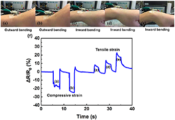
Figure 6. Flexible strain sensor of 200-cycle Ir NPs@CNTs petal patterned PDMS is used to detect wrist bending movement: (a), (b) outward bending of wrist with different degrees, (c)–(e) inward bending of wrist with different degrees, (f) the △R/R0-t curve of the sensor corresponding to different positions of wrist joint.
Download figure:
Standard image High-resolution imageIn figure 7(a), the flexible strain sensor is fixed on the radial artery with adhesive tape. Figure 7(b) shows the measured I-t curve of sensor during monitoring human pulse. The pulse frequency measured in the experiment is about 61 times/min. The response of each pulse wave is very regular, excluding the disturbance of electric current caused by slight movement of hand muscle. The percussion wave (P-wave), dicrotic wave (D-wave) and tidal wave (T-wave) in each pulse wave can be clearly distinguished, which come from systolic and diastolic blood pressure, heart rate and ventricular rate, respectively. This is in good agreement with literature report [40].

Figure 7. Flexible strain sensor of 200-cycle Ir NPs@CNTs petal patterned PDMS for human pulse monitoring: (a) picture of test process, (b) I-t curve of sensor.
Download figure:
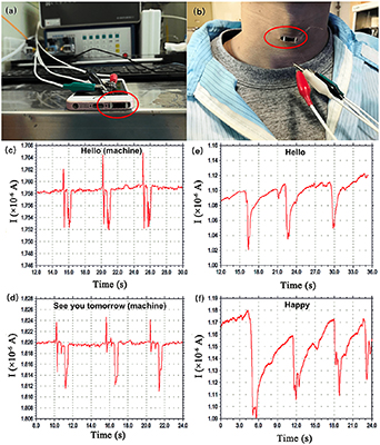
Standard image High-resolution imageWe have attempted to utilize flexible strain sensor in phonation detection. The sensors are fixed on the loudspeaker of the mobile phone and the throat of the human, respectively, as indicated in the red circles in figures 8(a) and (b). When the mobile phone or human speaks, the I-t curves of the sensors are measured. The phonation detection is realized by examining the vibration of the loudspeaker or the movement of the human neck muscles. Figures 8(c) and (d) shows the measured I-t curves of the sensor when playing the mobile phone audio of 'Hello' and 'See you tomorrow'. Every audio is repeated three times. For the same machine sound of 'Hello' or 'See you tomorrow', the sensor response is stable with repeatable waveform; for various sounds of 'Hello' and 'See you tomorrow', the current waveform of the sensor is quite different. Figures 8(e) and (f) records the I-t curves of the sensor for human voice of 'Hello' and 'Happy' for three times. It can be observed that for the same voice of 'Hello' or 'Happy', the current response has certain fluctuation. The repeatability is not as good as the above machine test results, but various voices have different current waveforms and can be distinguished. The disturbance is related to the slight motion of the neck muscles caused by human breath.
Figure 8. Flexible strain sensor of 200-cycle Ir NPs@CNTs petal patterned PDMS is used for phonation detection: (a) setup of machine phonation test process, (b) picture of human phonation test process, (c), (d) I-t curves of sensor for machine phonation detection, (e), (f) I-t curves of sensor for human phonation detection.
Download figure:
Standard image High-resolution image
Above all, flexible strain sensors of 200-cycle Ir NPs@CNTs petal patterned PDMS have exhibited prospects in wearable equipment, health monitoring, intelligent robot, etc.
4. Conclusion
We have successfully constructed a flexible strain sensor based on petal patterned PDMS film and Ir NPs@CNTs. The 200-cycle Ir NPs@CNTs petal patterned PDMS strain sensor shows best performance, such as sensitivity up to 20.33, sensing range of 0%–35%, response time of 242 ms and more than 9000 cycles of repeated stretch-release, which is ascribed to using Ir NPs@CNTs as sensing materials and petal patterned PDMS films as substrates. Furthermore, the biomimetic flexible strain sensor can be applied in human motion detection, pulse monitoring, and phonation detection, showing great potentials in wearable electronics, health monitoring, human motion detection, etc.
Acknowledgments
This work is supported by the Natural Science Foundation of China (51571111 and 51721001) and Jiangsu Province (BK20170645 and BK20201087).