

Abstract
Efficient direct electron acceleration in the plasma channel with injection through the breaking of plasma waves generated by parametric instabilities was demonstrated experimentally and reproduced in the 2D3V PIC simulations. The electron bunch was produced using the specific plasma profile containing arbitrary sharp, ∼0.5λ, gradient at the vicinity of 0.1–0.5 critical density and a long tail of a tenuous preplasma. Such a preplasma profile was formed by an additional nanosecond laser pulse with intensity of 5 × 10¹² W cm−2. In the case of optimal preplasma parameters femtosecond laser pulse with an intensity of 5 × 10¹⁸ W cm−2 and an energy of 50 mJ generates a collimated electron bunch having divergence of 50 mrad, exponential spectrum with the slope of ∼2 MeV and charge of tens of pC. The charge was confirmed measuring neutron yield from Be(g, n) photonuclear reaction with threshold of 1.7 MeV. By the contrast, a ring-like electron beam with divergency of 300 mrad and significantly lower charge is generated if the prepulse intensity drops to 5 × 10¹¹ W cm−2. The 2D PIC simulations confirmed beamed electron's acceleration in the plasma channel (so-called direct laser acceleration). This channel is formed in a long tail of teneous preplasma by the laser pulse specularly reflected from the arbitrary sharp gradient. The ring-like electron beam was attributed to the longer gradient case enlarging divergence of the reflected laser beam, preventing channel's formation and electron acceleration by the so-called vacuum laser acceleration, or VLA. We also showed that injected electrons appeared from the wave breaking of plasma waves of hybrid SRS-TPD instability for the both gradients. Electrons received an initial momentum from this breaking to be effectively injected into the plasma channel.
Export citation and abstract BibTeX RIS
Introduction
Femtosecond laser plasma is a novel source of electrons accelerated to high energies from MeV to GeV [1–3]. Applications demand low divergent electron beams useful for electron accelerators and Thomson x-ray sources, laboratory astrophysics, ultrafast electron microscopy, hard x-ray bremsstrahlung sources, nuclear spectroscopy, phase contrast x-ray imaging. The most advanced schemes explore wakefield acceleration in low density gases [4], while acceleration at dense plasma boundary provides much higher bunch charges but, in most cases, almost 2π divergence and a broad quasi-exponential spectrum [5–7].
Laser intensities routinely used in experiments amount up to 1021 W cm−2 nowadays [3], while nanosecond and picosecond contrasts of femtosecond laser pulses vary from 106 to 1012 [8][9]. Hence preplasma is unavoidably generated by a prepulse before reaching a peak intensity at a solid target surface. Its spatial extent a scale length 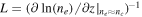 with ne and nc being the electron density and its critical value might vary from a few tens of the fundamental radiation wavelength λ to much shorter values, L ∼ 0.1λ, [8, 10] and even less with a high contrast laser pulse [11].
In recent years, many scientific groups observed beams of fast electrons from plasma created at a solid target [5, 8, 12–15], but there is no good understanding of optimum plasma conditions for production of a collimated MeV bunch of electrons. In [5] a non-thermal electron beam appeared in the interaction of relativistic laser pulse (1018 W cm−2 at not well defined contrast) with a silicon target. In [12], there was a study of electron acceleration by surface plasma waves excited at grazing incidence of high contrast laser radiation (1018 W cm−2) at the aluminum target. Also, grazing incidence of laser pulse was considered in [13–15] for much longer plasma gradients. Here a moving bubble-like structure supporting acceleration of electrons was observed in PIC simulations. In [16] electron beams was demonstrated with narrow energy spread in the 0.2–0.8 MeV range under interaction of femtosecond low contrast subrelativistic laser radiation (2 × 10¹⁷ W cm−2) with an edge of aluminum foil.
In [17, 18], it was shown that interaction of a relativistic ultrashort laser pulse with a sharp plasma-vacuum interface (L ≪ λ) leads to excitation of surface plasma waves. Fields of these waves accelerate electrons and eject them in the specular direction. These electrons are further captured by the field of reflected laser pulse and accelerated by the vacuum laser acceleration (VLA) mechanism [17, 19]. A characteristic feature of this regime is a ring-shaped electron beam structure [17].
In [20] subpicosecond laser radiation interacts at the oblique incidence (72°) with an artificially created preplasma having the scale length L ∼ 10λ. It was concluded from the PIC simulations, that as a result of the high, subPW peak power of the laser pulse and enough undercritical plasma length the laser beam broke down into a few channels. Electrons inside these channels gained energy due to direct laser acceleration (DLA) mechanism [21, 22] and beamed into the specular direction. The main difference between these two mechanisms of electron acceleration is that additional quasi-static fields inside a plasma channel confine electrons and help them to gain energy in the DLA regime, while electrons escape easily from the laser field in the VLA one.
In this paper, we show that by using an artificial nanosecond prepulse one can prepare a specific preplasma profile providing for the high charge, high energy, low divergent electron beam in the specular direction. We explored the intermediate case, L ∼ λ, that have not been well studied till now. Various instabilities should play an important role in such a plasma giving rise to excitation and breaking of resonant and parametric plasma waves at plasma densities varying from the quarter-critical to the critical one [23–26]. Electrons, which gained energy from the decay of parametric plasma waves, are further accelerated by the laser field. We observed that depending on the preplasma profile either VLA or DLA can occur. First, we present experimental data on the electron beam parameters and then discuss acceleration process in detail using PIC simulations.
Experimental setup and results
Experiments were carried out at the 1 TW TiSa laser facility of the International Laser Center of Lomonosov Moscow State University (800 nm, 50 mJ, 50 fs FWHM, 10 Hz). The amplified spontaneous emission appears 2 ns before the main pulse and has contrast of 10−7 by intensity to the main pulse 10 ps before it. Experimental setup is shown in figure 1. The p-polarized laser radiation was focused by the off-axes parabola (f = 10 cm) onto a tungsten target with an angle of incidence θ ∼ 45°. The focal spot in vacuum was 3 μm FWHM, thus giving peak vacuum intensity of 5 × 10¹⁸ W cm−2. This intensity was checked at the full energy using recently developed approach based on the angularly resolved electron spectra measurement [27]. We used additional Nd:YAG laser (1064 nm, 10 Hz, 200 mJ, 10 ns FWHM) to create a preplasma. Peaks of laser pulses coincided in time for this study with jitter less than 1 ns. This maximizes gamma yield (and yield of high energy electrons) [10]. The nanosecond beam was focused at the target surface by the same parabola. Intensity of this radiation can be varied from 5 × 10¹¹ to 5 × 10¹² W cm−2 by adjusting divergence of the nanosecond beam with a telescope (not shown in figure 1) thus changing the focal spot from 15 to 45 μm.

Figure 1. Experimental setup (see detailed description in the text).
Download figure:
Standard image High-resolution imageElectrons emitted from plasma in the specular direction were detected by an electron detector with LANEX scintillation screen, located 8 cm away from the plasma. A short-focus lens imaged the screen to a CCD camera, thus allowed us to visualize the electron beam. A 130 μm tungsten filter was placed on the top of the LANEX screen to cut off electrons with energy less than 1 MeV. A pair of magnets with field strength ∼0.15 T along with 2 mm wide slit can be inserted before the screen to measure energy spectrum of electrons (figure 1(b)). Spectrum retrieval from a resulting image was conducted using a code that calculates electron trajectories in the pre-measured magnetic field. Here we assumed flat sensitivity of the scintillator for electron's energies >1.5 MeV [28]. Additionally, a sheet of thin white paper was placed before magnets to record spatial distribution of the reflected laser radiation with a second CCD camera equipped with a band-pass filter at 800 nm. We used a Faraday cup (figure 1(a)) (copper cylinder with a diameter of 3 cm placed instead of the electron detector and connected to a 1 nF capacitor [29]) to measure electron beam charge with the same tungsten filter placed before the cup. The beam charge was calculated from a voltage at the capacitor.
We also used photoneutron yield measurements to make independent assess to an electron beam characteristics. Here a thick (2 mm) tungsten converter was placed at the electron beam path instead of the electron detector followed by the beryllium cube with 12 cm side(figure 1(c)). Bremsstrahlung gamma radiation created in the converter induced a photonuclear 9Be(g, n) reaction with an arbitrary low threshold of 1.7 MeV. Neutrons were detected with an array of 3He counters covered by a thick plastic moderator placed on air 40 cm apart from the Be cube. The detection efficiency of the whole device was estimated as 0.5% using a calibrated neutron source 252Cf placed instead of the laser plasma target [30]. Note that gamma emission from the laser plasma target itself (with the converter removed) induced zero detected neutron's flux above the background. This neutron detection setup was simulated using the GEANT 4.0 package using experimentally measured electron beam spectra (see below). The main output parameter of the simulation was the number of detected neutrons that is directly proportional to the electron bunch charge (if an electron spectrum is known). The typical calibration constant was ∼60 neutrons/pC for the exponential electron spectrum with the slope of 2 MeV. Thus, by measuring the neutron yield and electron spectrum it is possible to estimate the charge of electron beam for energies above 1.7 MeV.
The experiment was carried out at two intensities of the artificial prepulse: 5 × 10¹¹ and 5 × 10¹² W cm−2. Measured electron beam's parameters for these two intensities are presented in figure 2. A ring-shaped beam structure with a divergence of ∼0.3 rad is clearly observed at lower prepulse intensity (figure 2(a)), the slope of the high energy part of the spectrum is ∼1 MeV (figure 2(e), measurements for one of bright spots in figure 2(a)). The electron beam becomes much better collimated (∼0.05 rad) (figure 2(b)) and the slope increases to 2 MeV (figure 2(f)) at higher prepulse's intensity. Figures 2(c), (d) show the reflected laser beam. Its divergence is also lower at higher nanosecond pulse intensity and is of the same order as the laser beam divergence in a vacuum. For the case of the higher nanosecond laser pulse intensity beam charge measured by the Faraday cup was 30 ± 10 pC (for electron energies >1 MeV). Neutron yield measurements gave an estimation of 10 ± 4 pC for the total charge of electrons with energies >1.7 MeV. The electron beam jumps by an angle comparable to its divergence from shot to shot, but other parameters (energy and charge) remain close to the values given above. Measurements of the beam charge in the case of the lower nanosecond intensity were hampered due to the large angular divergence of the ring-like electron structure but judging by the brightness of the scintillation screen it was a few times lower (i.e. about one pC).
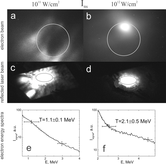
Figure 2. Images of the electron beam (a), (b) and the reflected laser beam (c), (d) as well as electron energy spectra (e), (f) at nanosecond laser pulse intensity of 1011 W cm−2 (a), (c), (e) and 1012 W cm−2 (b), (d), (f). Diameters of circles in figures (a)–(d) depict angular divergence of 0.2 rad.
Download figure:
Standard image High-resolution imageThe observed regime of collimated electron beam generation is obviously of greater interest for numerous practical applications than the ring-like beam. Now it is essential to shed a light onto the physical origin of these regimes. Obviously, the key issue here is the preplasma, namely its spatial profile. Interferometric measurements with probe wavelengths of 400 or 800 nm yielded gradient length of L ∼ 10λ if ne < 0.1 nc for plasma created by our nanosecond laser pulse [31]. This technique is inapplicable at higher densities due to a probe refraction [32]. We estimated the preplasma scale length near the turning point  (nc/2 for θ = 45°) based on the relative intensities of 2nd and 3/2 harmonics of a femtosecond laser pulse emitted from plasma [10]. This gave L = 1.5λ for the nanosecond laser pulse intensity of 5 × 10¹¹ W cm−2. Such a short gradient might be due to the plasma steepening near the turning point under action of ponderomotive forces that occurs even at intensities as low as 5 × 10¹¹ W cm−2 [26, 33]. In [26] it is shown that L ∼ vosc−1.1 near the turning point, where vosc is the quiver velocity of an electron. Thus, one can expect decrease in the plasma gradient length to 0.5λ with increase in the nanosecond laser pulse intensity to 5 × 10¹² W cm−2. In the following, using these estimates of preplasma parameters, we will proceed to the analysis of electron acceleration processes using PIC numerical simulations.
Numerical simulations
Numerical simulations of femtosecond laser plasma interaction were performed using the fully relativistic 3D3V Particle-in-cell code MANDOR [34] in 2D3V regime. Size of the simulation box was 30λ × 50λ, temporal and spatial resolutions of the numerical grid were 0.003 fs and 0.01λ, respectively. Temporal and spatial envelopes of the laser pulse were Gaussian with peak intensity of 5 × 10¹⁸ W cm−2. The laser pulse has duration of 50 fs FWHM and diameter of 4λ FWHM in the focal plane. P-polarized radiation was incident at 45°. Two different plasma gradients were used:  and
and  where
where  is the coordinate along the normal to the target surface,
  corresponds to the simulation box entrance boundary (figures 3(c), (f)). This preplasma profiles correspond to the two cases with nanosecond pulse intensities of 5 × 10¹¹ and 5 × 10¹² W cm−2 described above. Fields and electron density dependences on spatial coordinates and time, as well as trajectories of individual particles were saved for further processing with steps of 0.05λ and 0.1 fs, respectively.
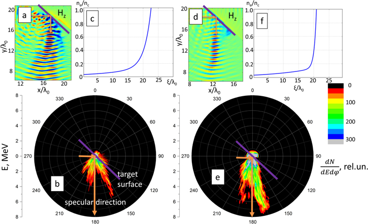
Figure 3. Numerical simulation results: angularly resolved energy spectra of high energy (above 1 MeV) electrons (b), (e), spatial distributions of the magnetic field Hz in plasma (a), (d), and initial electron density profiles (c), (f).
Download figure:
Standard image High-resolution imageFigure 3(b), (e) plot dependences of the electron density on energy and emission angle of electrons with energies above 1 MeV, while figure 3(a), (d) show spatial distributions of magnetic field Hz of the reflected laser pulse at instant t = 40 fs (t = 0 when half of the laser pulse is reflected). Large divergence of both the reflected optical radiation and the electron beam can be seen in the case L = 1.5λ. Degradation of the reflected laser pulse quality is mainly due to the parametric excitation of plasma waves and processes of linear transformation of laser radiation into plasma waves near the turning point [10]. Note, that our simulations well reproduced the ring-like structure observed experimentally (figure 2(a)). Trajectory analysis (see the next chapter) showed that electrons, gaining energy of a 1–5 hundred keVs from breaking of plasma waves around the turning point, undergone VLA up to few MeV in the tenuous plasma by the reflected laser pulse. Impact of plasma induced distortions is much weaker with gradient L = 0.5λ and the reflected laser pulse creates a channel in the tenuous plasma (figure 4). This channel supports DLA of electrons and formation of collimated jet of high energy electrons.
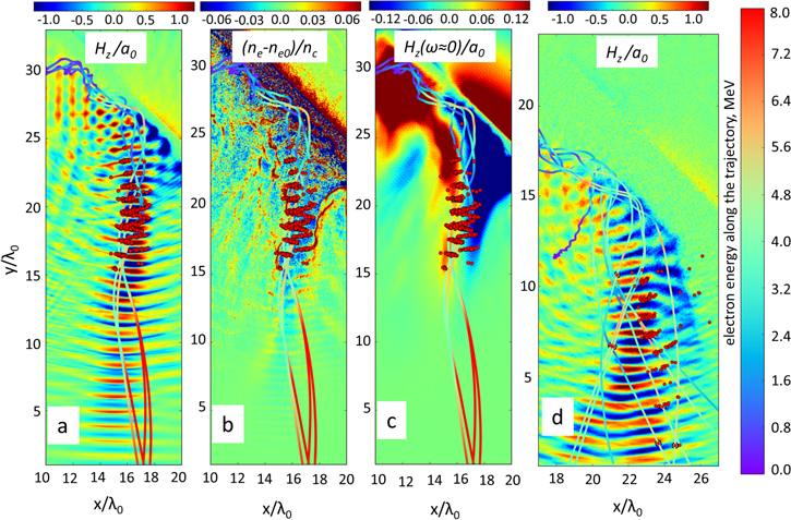
Figure 4. Magnetic field of the reflected laser pulse for L = 0.5λ (a) and L = 1.5λ (d), deviation of the electron density from the initial one (b), and a quasi-static magnetic field obtained by applying on the total field Hz the rectangular band-pass filter with zero central frequency and 0.1ω0 spectral bandwidth. Red dots indicate randomly chosen individual electrons that received the maximum energy (E > 6 MeV for L = 0.5λ and E > 4 MeV for L = 0.5λ) at the end of the channel. Colored lines are test particles trajectories with color scale reflecting an electron energy.
Download figure:
Standard image High-resolution imageThus, our numerical simulations qualitatively explains angular structure of electron and reflected laser beams observed in the experiment. In the numerical simulations electron beam divergence was approximately twice larger than in the experiment. This may be since experimentally obtained channel is longer than in simulations. It is also worth noting that simulations were performed in the 2D mode, therefore one should not expect adequate quantitative descriptions for self-focusing of a laser pulse and channel formation.
Electron acceleration
In this chapter we will focus on the analysis of electron acceleration mechanisms. Figure 4(a) shows the magnetic field at the fundamental frequency and trajectories of individual test electrons, which gained maximum energy by the end of the simulation, for the L = 0.5λ case. The ponderomotive force pushes electrons in a subcritical plasma away from the beam axis and this forms a channel with lower electron density (figure 4(b)). This causes self-focusing of the reflected laser beam and generation of an electrostatic field. Electrons accelerated by a propagating laser pulse along the channel create a current generating quasi-static azimuthal magnetic field (figure 4(c)). An electron moving in this combination of fields gain energy from the laser pulse, and this is exactly the DLA mechanism [21, 22].
Figure 4(d) shows magnetic field at the fundamental frequency ω0 and trajectories for the L = 1.5λ case. There is no channel here since the laser beam diverges strongly, and electrons are pushed out of the laser beam axis by the ponderomotive force. Hence, electrons gained less energy and resulting electron beam has the characteristic ring-like structure.
An important issue of the acceleration process is electron's injection into an accelerating filed, i.e. that initial energy and position of an electron inside this field provide for the highest energy gain at the end of the acceleration process. We used a simple 2D code that integrates relativistic equations of motion of an electron in a complex electromagnetic field consisting of the laser pulse (in the plane wave approximation) and static channel electric and magnetic fields to shed a light into optimal injection conditions. The laser pulse was given by  τ = 50 fs,
 is the normalized vector potential. Channel fields were set as
 [22], field amplitudes and laser beam radius in the channel were close to those observed in the PIC simulations. Test electrons were placed at different points in space along x with z = y = 0 having different initial momenta in the +x direction with homogeneous distribution in energy space within 0–1.5 MeV range. Motion of each electron was then calculated till x = 30λ and dependence of the final kinetic electron energy on its initial kinetic energy and x-position was plotted.
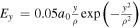
Resulting plots with switched off (VLA case) and switched on (DLA case) quasi-static channel fields are shown in figure 5(a), (b). Optimal conditions for injection of an electron for acceleration in the VLA case are (i) injection into the maximum of laser pulse envelope in the certain phase of this field (close to zero field values) providing initial acceleration toward +x direction and (ii) injection with maximal initial energy. The situation is quite different for the DLA case: optimal initial kinetic energy of an electron is 400 ± 200 keV and its final energy for the considered interaction length is 1.5 times higher than in the VLA. Note, this optimal energy increases but remains within hundreds of keV if an electron has some initial transversal momentum. Thus, an electron must be injected into a channel with an energy of several hundred keV near the maximum of laser pulse envelope to be accelerated efficiently in both cases.
Figure 5. Dependence of an electron energy at the end of simulation with the laser pulse field only (a) and with presence of quasi-static plasma channel fields (b) on its initial kinetic energy E0 and x-position. The initial laser field is shown by the white line.
Download figure:
Standard image High-resolution imageSource of such energetic electrons is the hybrid SRS-TPD instability [35], which develops in an undercritical plasma near the turning point. Plasma waves grown from this instability have characteristic wavenumbers kp ∼ k0, where k0 stands for the wavenumber of the laser field [35, 36]. Amplitudes of these waves increase up to the wave breaking limit  where
where  —phase velocity of the plasma wave and
  since these instabilities develop near nc/4 [37]. Therefore, maximum energy gain for an electron initially at rest can be estimated as
  which is of order of mec2 = 511 keV. Thus, plasma waves can be an efficient source of electrons for injection into the plasma channel. In the next chapter we will consider trajectories of an individual electron to unveil injection and acceleration processes in more details.
Trajectory analysis and mechanisms of injection
Let us consider electron injection and acceleration for the case L = 0.5λ in more details. We randomly chose the single test macroparticle for analysis (but we will call it an electron below), which gained maximal energy by the end of the simulation. It is convenient to calculate energy gains in longitudinal and transverse fields separately analyzing acceleration processes in plasma channels [20, 38, 39]. This allows understanding kind of fields the main gain comes from (plasma waves, quasi-static fields or laser pulse). In our case, due to the presence of both incident and reflected laser radiation, it is impossible to separate fields into longitudinal and transversal ones. Instead we used the following procedure. Any field consists of the divergence-free and curl-free components  (here A and φ are vector and scalar potentials in the Coulomb gauge). From our PIC simulations we can get distributions in space of three components of electric and magnetic fields, as well as the electron density
  at a given instant. Solving the Poisson equation
  one can obtain the curl-free part of the field,
  and from
  with gauge considered, the divergence-free one,
Partial work of a force on a test electron with charge -q from these two field components were calculated as 
 Comparing these quantities one can look at relative impacts to the instant energy of an electron by these two components. Note, that plasma waves have a small divergence-free component in an inhomogeneous plasma, while electromagnetic waves create some charge separation. Therefore, it is impossible to separate their action on a test particle accurately, but our approach is applicable for the rough qualitative analysis.
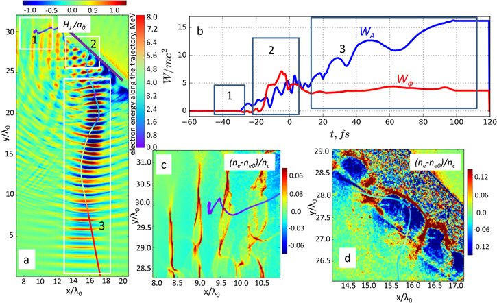
Figure 6(a) shows spatial distribution of the Hz component of the laser field at the instant t = 40 fs and trajectory of the test electron, while figure 6(b) shows temporal dependences of WA and Wϕ quantities calculated along this trajectory. There are clearly 3 stages in the process of electron acceleration marked with white boxes in figure 6(a). At the first stage intense laser radiation interacts with plasma at densities below a quarter-critical and plasma waves rapidly arise due to SRS instability [26]. Its increment is quite large, and in just a few periods of the laser field amplitudes of these waves reach the wave breaking limit at this density (figure 6(c)). Initially electrons oscillate in a plasma wave around their initial equilibrium positions without gain in energy. However, some of them are captured by the plasma fields after wave breaking and leave the region 1 almost along the surface toward the region 2 near the turning point. There is no significant increase in an electron energy at this stage.
Figure 6. The magnetic field Hz of a laser pulse and trajectory of the test particle (a), energy gain of the test electron due to the divergence-free and curl-free components of the electric field (b), electron density maps showing plasma waves at instant of wave breaking (c) and injection into the plasma channel (d). The color of the trajectory corresponds to the electron energy. The energy gain is normalized to mc2, t = 0 fs when half of the laser pulse is reflected.
Download figure:
Standard image High-resolution image
Near the turning point (unperturbed ne ∼ nc/2, region 2 in figure 6(a)) electron density decreases down to the quarter-critical value due to the ponderomotive pressure of intense laser radiation and relativistic effects, and plasma waves develop through the hybrid SRS-TPD instability [35]. Plasma waves in the region 2 and trajectory of the test electron are shown in figure 6(d). Amplitude of the plasma wave is larger in this region because of the higher plasma density, and electron starts to gain energy mostly from plasma fields, as one may see in figure 6(b). Two plasma waves are excited in the region 2: (i) one directed along the surface of the quarter-critical density with kp ∼ k0 and (ii) the second one having one spatial oscillation along the electron density gradient. Phase velocity of the first wave is  and electron, acquired energy up to a few hundred keV, undergoes dephasing which results in decrease in the
  (see figure 6(b)). This slightly decelerated electron is also pushed out of the plasma wave in specular direction by the field of the second wave (figure 6(d)). Thus, the electron receives an initial momentum in a direction close to the direction of the plasma channel. Plasma waves develop before the maximum of the t = 0 instant (when the maximum of the laser pulse envelope passes through the turning point) if intensity is high enough, so the waves can inject some electrons near the maxima of the laser pulse envelope. Those electrons fall into the optimal conditions for acceleration at the stage 3, that is the DLA (see figure 5(b)).
The first two stages of electron acceleration are almost the same for L = 0.5λ and 1.5λ cases, but the final third stage is the DLA at L = 0.5λ and the VLA at L = 1.5λ. Region 3 in figures 6(a), (b) corresponds to the first case. One can see that at this stage electron gains energy from the divergence-free part of the electric field. The electron experiences a few oscillations inside the channel till its end, while in the second case there is only one oscillation after which an electron is expelled out of the laser pulse by the ponderomotive force, and the final energy is lower. All the electrons gaining energy above ∼4 MeV by the end of our simulations were accelerated through the described three stage process. The only difference between them was in the initial position: most of them were located in the region 1, as described above, while others were in the region 2 initially.
The mechanism of electron bunch formation observed and described above to some extent is like the hybrid wakefield-DLA acceleration in tenuous plasma [40]. Here electrons are accelerated in a plasma wakefield at first and catch up the laser pulse, and then the main energy gain comes from the DLA by the laser pulse field. The fundamental difference is in the mechanism of electron injection. Wave breaking of plasma waves in denser plasma results in much larger charge of the electron bunch in our study as compared to the ionization injection under wakefield acceleration in [39]. It is important to note that in our case the wave breaking of plasma waves of parametric instabilities occurs along the target surface (almost parallel to it) and not in perpendicular direction as in [41]. Number of electrons released by the breaking of plasma waves that are injected into the plasma channel is about 10%. More detailed analysis of the wave breaking and capturing of electrons by channel's fields will be presented in a separate paper.
Conclusions
Hence, we demonstrated efficient electron acceleration in the plasma channel with injection through the breaking of plasma waves generated by parametric instabilities. It was shown experimentally that in the case of optimal preplasma parameters femtosecond laser pulse with an intensity of 5 × 10¹⁸ W cm−2 and an energy of 50 mJ generates a collimated electron bunch having divergence of 50 mrad, exponential spectrum with the slope of ∼2 MeV and charge of tens of pC. The charge was confirmed measuring neutron yield from Be(g, n) photonuclear reaction with threshold of 1.7 MeV.
This bunch was produced using the specific plasma profile containing arbitrary sharp gradient at the vicinity of 0.1–0.5 critical density and a long tail of tenuous preplasma. We successfully formed such a gradient by an additional nanosecond laser pulse with intensity of 5 × 10¹² W cm−2. Its intensity must be enough for the plasma gradient steepening down to L ∼ 0.5λ by the ponderomotive force. This steepening happens near the critical density and provides for the efficient reflection of the subsequent femtosecond laser pulse of relativistic intensity. This reflected pulse creates plasma channel that serves for the DLA of electrons. Finally, well collimated bunch of high energy electrons emerges with mean electron energy well above the ponderomotive energy of the femtosecond pulse.
The steepening is much weaker at lower intensities of the nanosecond laser pulse, and relativistic femtosecond laser pulse experiences strong absorption and scattering. The pulse, reflected under these conditions, does not create a channel in plasma and the VLA of electrons occurs, resulted in the larger divergence and lower energies and charge of the electron bunch. Our calculations shown that at the higher steepening of L ∼ 0.25λ electron beam charge decreased by a factor of ∼2. This is due to the smaller volume of plasma from which electrons enter the channel and changing of electron injection source from parametric plasma instabilities to surface plasmons [18, 42]. Additional calculations showed that L ∼ 0.5λ is the optimal scale length for the considered mechanism of electron acceleration.
Simulations of a test electron's motion in the complex electromagnetic field consisting of the laser pulse and static electric and magnetic fields showed that an electron acquires maximum energy at the channel exit if its initial energy amounts to several hundred keV and it is injected at the instant of the maxima of the laser pulse envelope. Simple estimates showed that plasma waves of the hybrid SRS-TPD instability are capable of injecting electrons with required energies in the channel. This instability generates two groups of waves: one moves along the plasma surface and the other—approximately in the perpendicular direction toward lower densities. Analysis of electron's trajectories obtained from the PIC-modeling showed that the first group of waves accelerates electrons, while the field of the second group pushes electrons into the plasma channel. These waves were evidenced experimentally and numerically from the scattered 3/2w0 harmonic.
The briefed mechanism of injection requires deeper insight, while the acceleration regime described could be further optimized. In particular, it is of special interest to check its applicability at higher intensities to path a way to the table top production of well collimated electron bunches with high, tens of nC, charge and mean energy (or slope) above 10 MeV.
Acknowledgments
This work was supported by RFBR Grants 19-02-00104_a, 18-32-00868_mol-a. PIC calculations were made using Moscow State University Supercomputing Facility 'Lomonosov'. D A Gorlova acknowledges foundation for theoretical research 'Basis' for the financial support.