

Abstract
The vibration responses of structures under controlled or ambient excitation can be used to detect structural damage by correlating changes in structural dynamic properties extracted from responses with damage. Typical dynamic properties refer to modal parameters: natural frequencies, mode shapes, and damping. Among these parameters, natural frequencies and mode shapes have been investigated extensively for their use in damage characterization by associating damage with reduction in local stiffness of structures. In contrast, the use of damping as a dynamic property to represent structural damage has not been comprehensively elucidated, primarily due to the complexities of damping measurement and analysis. With advances in measurement technologies and analysis tools, the use of damping to identify damage is becoming a focus of increasing attention in the damage detection community. Recently, a number of studies have demonstrated that damping has greater sensitivity for characterizing damage than natural frequencies and mode shapes in various applications, but damping-based damage identification is still a research direction 'in progress' and is not yet well resolved. This situation calls for an overall survey of the state-of-the-art and the state-of-the-practice of using damping to detect structural damage. To this end, this study aims to provide a comprehensive survey of uses and features of applying damping in structural damage detection. First, we present various methods for damping estimation in different domains including the time domain, the frequency domain, and the time-frequency domain. Second, we investigate the features and applications of damping-based damage detection methods on the basis of two predominant infrastructure elements, reinforced concrete structures and fiber-reinforced composites. Third, we clarify the influential factors that can impair the capability of damping to characterize damage. Finally, we recommend future research directions for advancing damping-based damage detection. This work holds the promise of (a) helping researchers identify crucial components in damping-based damage detection theories, methods, and technologies, and (b) leading practitioners to better implement damping-based structural damage identification.
Export citation and abstract BibTeX RIS

Original content from this work may be used under the terms of the Creative Commons Attribution 3.0 licence. Any further distribution of this work must maintain attribution to the author(s) and the title of the work, journal citation and DOI.
1. Introduction
A structural health monitoring (SHM) system is designed to reliably monitor, inspect, and test the health and performance of structures such as buildings, bridges, dams, and tunnels, with the aim of helping engineers improve the safety and maintainability of critical structures [1–3]. The SHM system is essentially comprised of two major components: smart sensing technologies and damage detection algorithms [4]. The smart sensing technologies, e.g., fiber optic sensors [5, 6] and piezoelectric sensors [7], are utilized to monitor various physical or chemical responses of the structures under investigation. The damage detection algorithms are employed to reveal damage characteristics from the responses measured by smart sensing sensors and to associate them with the health and performance of the structures [8]. In recent years, a series of smart sensing technologies have emerged, making acquisition of various responses of structures simple and convenient [3]. In this situation, the development of efficient and effective methods to process responses for damage detection in structures is a crucial scientific and technological issue, and also the major focus of SHM systems [9].
Damage detection is a feasible way of avoiding structural failure and catastrophic events induced by structural damage. Structural damage detection methods developed over the last two decades can be categorized into two groups: local inspection methods [10] and global detection methods [8, 9]. Local inspection methods are commonly based on localized inspection procedures that include ultrasonic and acoustic methods [11, 12], x-ray methods, magnetic field methods, eddy-current methods, thermal field methods, etc [13–15]. Such inspection procedures require that the vicinity of damage be known a priori and that the portion of the structure under investigation be readily accessible for testing [8, 9]. Unfortunately, in a large number of cases this requirement cannot be guaranteed, such as when the structure is large and complex or its operating environment is hostile. Hence, local inspection methods must be limited to damage detection in certain simple structures operating under friendly conditions. These limitations have resulted in the rapid development of global detection methods in the recent decade [16–19]. Global detection methods usually rely on changes in structural vibration properties to characterize damage. In this group of methods, the basic premise is that the dynamic properties described by structural modal parameters (natural frequencies, mode shapes, damping) are functions of structural physical properties [20–22], and damage occurring to a structure causes changes in structural physical properties, in turn manifesting in changes in modal parameters. Hence, changes in structural modal parameters can be taken as signatures of the existence, location, and severity of damage in a structure [23, 24]. Vibration-based structural damage detection can effectively avoid the limitations of local inspection methods because it does not require that the vicinity of damage be known a priori, nor that the structural portion of interest be readily accessible for testing.
Overall reviews of vibration-based structural damage detection can be found in the literature [25–31]. Methods proposed in the literature mostly portray damage using either natural frequencies or mode shapes and their derivatives such as displacement modal curvatures [32–36]. It is generally acknowledged that natural frequencies have low sensitivity to damage, so that they can usually be used to reflect damage to a moderate degree [37]. Compared to natural frequencies, mode shapes and their derivatives have greater sensitivity to damage. However, the measurement of a mode shape requires numerous sensors distributed on the structure [38]. That this requirement cannot be realized in reality creates difficulties in utilizing mode shapes and their derivatives to represent damage in practical applications of structural damage detection.
Compared to natural frequencies and mode shapes, damping has been less frequently applied to the identification of structural damage, mostly due to the difficulty involved in traditional measurement means and the complexity of its mechanism. Noticeably, in the measurement aspect, smart sensing technologies have made the acquisition of various dynamic responses of structures feasible, providing more convenient means of obtaining damping [39, 40]. In particular, piezoelectric sensors and fiber optic sensors, surface-bonded or embedded in the structure, can serve as both sensors and actuators, allowing SHM to become an active monitoring system [3], facilitating damping acquisition. In the mechanism aspect, damping represents a physical mechanism that dissipates vibration energy in dynamic systems [41–43]. Commonly, much of this energy dissipates within the system, mostly in the form of heat, while the rest dissipates outside the system in the form of acoustic radiation [44]. There are as many forms of damping mechanism as there are modes of converting vibration energy into heat. The forms of damping mechanism include, for example, atomic-molecular microstructure effects, kinetic friction between parts, transmission of kinetic energy through the structure's foundation, viscosity in materials, and fluid-structure interactions [45]. Combinations of different forms of damping mechanism result in three fundamental types of damping: material damping, structural damping, and fluid damping [45]. Material damping arises from a complex atomic-molecular interaction within the material; structural damping is produced from Coulomb friction between members and connections of a structural system; fluid damping arises from the aerodynamic and hydrodynamic forces of the fluid surrounding the structure [46].
Owing to the complexity of damping mechanisms, it is difficult to define a particular damping in a certain real physical circumstance using exact mathematical expressions. To this end, researchers have proposed a number of simplified models to represent damping, typically viscous damping [47, 48], defined on the hypothesis of the damping force being proportional to the velocity of oscillation. Viscous damping is the most widely used damping model because of its mathematical simplicity. Apart from viscous damping, two other commonly used damping models are hysteretic damping and Coulomb frictional damping [49]. In real structures, different types of damping often act simultaneously; this in practice leads to the concept of equivalent viscous damping that models the overall damped behavior of the system as viscous.
Applicable damping models improve the feasibility of using damping to identify structural damage. Moreover, advances in vibration measurement technologies, such as laser scanning vibrometer, and the development of damping analysis methods greatly facilitate the estimation of damping. On that basis, the use of damping in structural damage detection has become a research focus of increasing interest in the recent decade. Representative studies are those of Curadelli et al [50], Kyriazoglou et al [51], Frizzarin et al [52], Kostka et al [53], Wei et al [54]. In particular, some studies have reported that damping has the potential to characterize damage with greater competence than natural frequencies and mode shapes in some circumstances [55, 56]. Meanwhile, the factors that influence the capability of damping in characterize damage have attracted much attention [57, 58]. On the whole, extant studies of the use of damping for damage characterization are attractive, but loose and disperse, and this situation calls for a comprehensive review of the state-of-the-art and the state-of-the-practice of this emerging area, that could help new researchers identify starting points for investigation in damping-based damage detection and could guide practitioners in better implementing available damping estimation and damage detection based on damping.
The remainder of this paper is outlined as follows. Section 2 provides a survey of typical methods for damping estimation in structural damage detection. Section 3 overviews the features and applications of damping for use in structural damage identification. Section 4 reveals the factors that influence the outcomes of the use of damping to identify structural damage along with possible measures to address those factors. The final section recommends potential directions for research into the development of new theories and technologies of damping-based structural damage detection.
2. Methods of damping estimation
Damping is quantitatively represented by a damping measure, typically the damping ratio [45, 59], to indicate the magnitude of the damping of a structure in actual applications. The damping ratio can be estimated through the procedure of parameter identification from vibrational responses of a structure. In this sense, damping estimation refers to damping parameter identification. A series of methods can be found in the literature for identifying damping ratios, and they can be in principle classified into three groups: time-domain methods, frequency-domain methods, and time-frequency-domain methods [60–62].
2.1. Damping estimation in the time domain
Popular time-domain methods for estimating damping include the logarithmic decrement method [63–65], the Ibrahim time-domain method [66], the random decrement method [67, 68], and the Hilbert transform (HT) method [69, 70]. Among these methods, the logarithmic decrement method is considered as representative due to its fundamental and straightforward nature, and it is the most frequently used for damage detection [71]. This method uses a procedure of calculating the damping ratio with the logarithmic decrement  described by the following expressions:

where  and
and  are two successive peaks in the free vibration response of the structure and
  is the damping ratio. For a small damping ratio with
  and
and  the damping ratio
  can be derived from equation (1) as

To improve precision, two particular peaks with m cycles between them can be utilized to calculate the damping ratio:

Equations (2) and (3) provide the basic paradigm for identifying damping ratio from free vibration responses of structures.
It should be noted that, despite the prevalence of the logarithmic decrement method, two concerns exist when using it to estimate the damping ratio: (i) The peak values of a free vibration response are identified by the sampling values, and as such they are not certain to be equal to the actual maximum values of the response, giving rise to the occurrence of measurement error. (ii) The damping ratio is determined by temporal information from a vibration response, but temporally measured data is easily contaminated by noise. To obtain a precise damping ratio, measures to improve the anti-noise ability, precision, and stability of damping estimation are key in actual applications [72].
2.2. Damping estimation in the frequency domain
Prevalent frequency-domain methods for estimating damping are the half-power bandwidth method [73], the peak picking method [74], and the frequency-curve-fitting method [75]. Among these methods, the half-power bandwidth method is the most representative and is widely used in applications due to the clarity of its implications and its simplicity in implementation [76]. The definition of this method is based on the fact that the width of the frequency response amplitude of a single-degree-of-freedom (SDOF) system is proportional to the damping ratio of the system. Let  be the resonant frequency and
 the particular frequencies at the left-hand and right-hand sides of
  respectively, with the amplitude of
  and
and  being
being  times that of
  Then, the damping ratio is defined as

Despite its clear implications and easy implementation, the half-power bandwidth method suffers from some limitations in estimating damping in actual applications. For one thing, it is applicable for small damping cases; for the other, when the peak of a frequency response is missing, the corresponding bandwidth tends to be greater than the real one, and as such the damping ratio derived from equation (4) is often overestimated [77].
2.3. Damping estimation in the time-frequency domain
Time-frequency-domain methods for estimating damping have emerged more recently than the aforementioned time-domain and frequency-domain methods. Time-frequency-domain methods usually reveal damping using the joint temporal and frequency characteristics of structural vibration responses obtained by time-frequency analysis methods. Methods that can be used to perform time-frequency analysis include the Wigner-Ville distribution [78], the short-time Fourier transform [79], the Choi-Williams distribution [80], and the continuous wavelet transform (CWT) [81]. Among these methods, the CWT time-frequency analysis is the predominant technique and has been increasingly used for damping identification in various applications, e.g., in bell type structures [82], in ocean engineering [83], and in rotor-bearing systems [84].
The basic procedure of wavelet-based damping estimation was presented in [44, 85]. Consider an asymptotic sinusoidal signal of the SDOF system:

where  is the phase and
  is the amplitude given by

where  is the damping ratio and
  is the undamped natural frequency.
The wavelet transform of  using the Gabor wavelet as the analyzing wavelet is expressed as
where the prime means differentiation operation,  is the approximation error, and
  is the Fourier transform of the translated-and-scaled Gabor wavelet, defined by

If  is larger than the bandwidth of the translated-and-scaled Gabor wavelet function
  the approximation error
  can be neglected, leading the approximate form of equation (7):

From equations (6), (8), (9) and using 
 the approximate expressions of
  and
and  can be derived as


where  is the ridge of the CWT and
  the damped natural frequency. Thus the damping ratio
  can be estimated from the slope of the straight line of
  .
.
Besides the basic procedure of wavelet-based damping estimation, the alternatives to using CWT time-frequency analysis to identify damping are as follows. Staszewski et al [86] formulated three time-frequency methods of damping identification: the CWT cross-section method, the impulse response recovery method, and the wavelet ridge method, by using the Morlet wavelet transform to decompose the impulse responses of multiple-degree-of-freedom (MDOF) systems into single modes. Ruzzene et al [87] developed a CWT procedure using the Morlet wavelet to extract damping of MDOF systems and showed that CWT-based method represents a consistent improvement for estimating damping compared to the HT. Lamarque et al [88] presented a wavelet-based formula identical to the logarithmic decrement equation developed in the frame of both a CWT and a multiresolution representation [89]. Their method featured decoupling of modes and estimating damping ratios simultaneously, and was validated experimentally using the dynamic responses of a civil engineering building subjected to both harmonic and shock excitations [90]. Lardies et al [91, 92] introduced a modified Morlet wavelet function for estimating damping from free vibration responses of a structure and the use of a modified Morlet wavelet function improved the resolution so that close modes can be identified. The technique was validated by identifying damping of a TV tower from the ambient vibration responses preprocessed by the conventional random decrement technique (RDT). Le et al [93] presented a new method that directly uses the raw ambient response with CWT by modifying the formulation of the CWT of the ambient response, thereby avoiding RDT preprocessing. Yin et al [94] proposed a damping estimation method based on the wavelet transform of frequency response functions with the advantages of simplicity and the ability to give a quick estimation. Due to the susceptibility of the CWT to the edge effect, which causes a non-valid identification at the start and the end of the time-series, some methods have been studied that will minimize the edge effect of the CWT [95, 96]. Lardies et al [97] employed cross-sections, ridges, and skeletons of the CWT to identify and quantify damping in a nonlinear oscillator using its free decay response, with the effectiveness of the methods verified. The attempts to identify nonlinear damping using wavelet transform were also reported by Staszewski [98], Ta et al [99], and Chandra et al [100]. The synchrosqueezed wavelet transform (SWT) has also been used for damping identification [101, 102], and it was found that although the SWT produces sharper representations, when identifying damping, it is less stable than the CWT-based approach.
Unlike the methods for estimating damping in the time only or frequency only domains, damping estimation in the time-frequency domain, especially using wavelet-based time-frequency analysis methods, enjoys the following distinct advantages: (i) It inherits the merits of wavelets in being self-adaptive to noise so that it can accurately estimate damping from actually measured vibration responses contaminated by noise. This feature enables the method to overcome the typical deficiency in time-domain methods of proneness to noise during damping estimation. (ii) It can estimate the instantaneous damping of structures [103], which makes it feasible for characterizing nonlinear damage that induces changes in structural dynamic properties in a nonlinear manner. This function cannot be realized in either time-domain or frequency-domain methods. (iii) It has the capability of decoupling MDOF systems into multiple single modes and analyzing damping simultaneously on this set of single modes. One concern regarding the use of the wavelet-based time-frequency method to estimate damping is proper selection of the analyzing wavelet [104]. Different analyzing wavelets probably lead to slightly inconsistent damping estimation results. Therefore, selection of the optimal analyzing wavelet is an issue worthy of exploration.
3. Damage identification using damping
The accurate estimation of damping paves the way to employing damping to characterize damage in structures. Several investigators have demonstrated the considerable potential of damping in acting as a viable damage signature [105–109]. The use of damping to portray damage has been reported for a wide spectrum of applications in various structures [50–54, 110, 111], with the most representative applications being reinforced concrete (RC) structures and fiber-reinforced (FR) composites. Dramatically, the methods of damping-based damage identification in these two structural types can cover almost all the methods available in the area of structural damage detection relying on damping. For this reason, this section surveys the use of damping in detecting damage in both RC structures and FR composites, with the aim of presenting a profile of damping-based damage identification in structures.
3.1. Effects of damage on damping
When characterizing damage using damping, above all the effect of damage on damping should be revealed. Theoretically, damage causes changes in structural dynamic properties including natural frequencies, mode shapes, and damping, and therefore a change in damping can be utilized to reflect damage. Notably, studies of the effect of damage on damping are promising but not as extensive as investigations of natural frequencies and mode shapes.
For RC structures and FR composites, various studies have investigated the effect of damage on damping, with some interesting findings [112–118]. Here, representative studies are summarized. Dieterle et al [119] experimentally and numerically investigated the damping behavior of cracked RC beams. They found that cracks could induce a considerable increase in damping. Daneshjoo et al [120] examined variation in the damping of cracked RC beams, with the phenomenon of damping increasing along with the observed development of cracks. Bovsunovsky et al [121] utilized a finite element model to predict changes in the damping of cracked beams. They found that the damping of the cracked specimens was greater than that of intact specimens. Panteliou et al [122] calculated the damping of a bar both analytically and experimentally. The results showed that the change in damping correlated well with the crack depth. Consuegra et al [123] conducted quasi-static testing on a structure which experienced three different drift levels and found that the damping ratio increased with the perceived drift level. Savage et al [124] observed that unstressed beams had a significantly higher damping ratio than prestressed beams. This phenomenon could be explained by the fact that micro-cracking along the length of the beam caused friction within solid concrete, and this friction could increase the damping ratio. In the prestressed beam, microcracks were effectively closed up by the post-load, so that the friction motion was reduced, resulting in a lower damping ratio, whereas this phenomenon could not occur in the unstressed beam, without a reduction in the damping ratio. Nelson et al [125] reported that the increase in damping due to fiber–matrix interfacial slip was significant, with the possibility of quantifying fiber–matrix interface damage from dynamic hysteresis measurements. Li et al [126] explained that damage was a mechanism that causes increased damping in composite materials. Kıral et al [127] presented the effect of impact failure on the natural frequency and damping ratio of a composite beam. Their results showed that the change in the natural frequency due to damage was not considerable and had irregular behavior, whereas the damping ratio increased at a measurable level as the damage level increased and the increase in the damping ratio was related to the friction due to the matrix cracks and broken fibers. Zhang et al [128] studied the damage process caused by fatigue in unidirectional fiber composites by using damping measurements. Damping showed an increasing trend with the fatigue cycles and a 'damping plateau' was detected that could be due to the balance between fatigue input energy and amount of energy dissipation of the microcracks. They also reported that damping was more sensitive than stiffness in the evaluation of damage process. Birman et al [129] presented an analytical solution capable of predicting the effect of matrix cracking in ceramic matrix composites on damping. Damping increased with a higher density of matrix cracks and the increase in damping associated with matrix cracking was mostly due to frictional energy dissipation along the damaged fiber–matrix interfaces adjacent to the bridging cracks whose plane of propagation intersected the fiber axis.
The foregoing studies imply a rule that damping is positively correlated with the degree of damage, specifically that damping increases with an increase in the degree of damage, with emphasis on the sensitivity to damage reflected in damping being greater than that in natural frequencies and mode shapes. This rule provides a basic guide for using damping as an efficient dynamic feature to detect, locate, and quantify damage.
Aside from this general deduction, a few studies have displayed observations of anomalous trends in damping changes with damage. Casas et al [130] performed tests on partially cracked concrete beams. Their results indicated no clear relation between crack growth and increase in damping. Williams et al [57] conducted tests of damping before and after structural repairs to a RC bridge, with no clear trend found in damping variation. Salane et al [131] reported that damping ratios decreased after damage was induced in a single-span bridge, whereas damping initially increased and subsequently decreased when damage was induced in the full-scale bridge model. Hearn et al [20] conducted tests on a steel frame subjected to sine wave load cycles while they monitored its damping. They noted that after damage, the damping might not remain at an increased level and could decline after continued deterioration of a member.
These observations can be interpreted to demonstrate that there are some uncertainties in characterizing damage using damping. The uncertainties can be attributed to the multiple factors influencing damping to represent damage (see section 4). Moreover, the definition of damage is also a factor that affects damping to portray damage. For instance, in laboratory tests an artificially manufactured crack or slot is usually utilized to define damage in a specimen, but from the point of view of damping inducing energy dissipation, those artificial phenomena are not related to damping since they cannot dissipate any energy.
3.2. Damping-based damage detection in RC structures
RC structures provide a relatively inexpensive and durable material with extensive applications in various infrastructure. However, the deterioration of in-service RC structures is a serious problem that impairs their performance and even threatens the safety of the infrastructure. Deterioration of RC structures can result from insufficient reinforcement, large deflection, poor concrete quality, and steel corrosion linked to environmental conditions. Damage caused by deterioration in RC structures has a significant influence on damping, providing the opportunity to use damping to detect damage in RC structures. The use of damping to characterize damage in RC structures is described in terms of linear and nonlinear features of damping.
3.2.1. Linear features of damping
The damping ratio defined by equations (1)–(3) is a linear feature of damping, representing the extent of energy dissipation within the system. The presence of damage causes energy to dissipate through the defects, thereby increasing the damping ratio. This relation explains the principle of using changes in damping ratio to characterize damage in structures.
Shahzad et al [71] examined the feasibility of detecting corrosion damage in RC beams based on changes in damping ratio. The damping ratio was identified by the logarithmic decrement method as well as the curve fitting method. The authors presented the findings shown in figure 1: (i) the damping ratio increased with the increase in corrosion damage, and (ii) the damping ratio was more sensitive than natural frequencies to corrosion damage in RC beams. Razak et al [76] experimentally investigated the effect of corrosion on damping as well as on other modal parameters of RC beams. The estimated damping ratios for the second and third modes reflected a trend of positive correlation with the severity of corrosion damage, but this relation did not exist for the first mode. The inconsistency with the first mode could be attributed to the enhanced bond at the steel–concrete interface due to the accumulation of rust products, in comparison with the uncorroded beam. This occurrence is probably a unique characteristic of corroded structural elements.
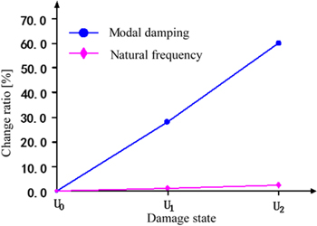
Figure 1. Variations in modal damping and natural frequency with increased severity of corrosion damage [71]. U0, U1, U2 denote damage states 0 (undamaged), 1, and 2, respectively.
Download figure:
Standard image High-resolution image3.2.2. Nonlinear features of damping
3.2.2.1. Instantaneous damping coefficient
The instantaneous damping coefficient is an extension of the damping ratio, suited to describing the variation of damping with evolution over time. Curadelli et al [50] presented a new scheme of using the instantaneous damping coefficient to detect structural damage, where the instantaneous damping coefficient is obtained by employing the CWT to process the vibration response. The complex behavior of RC beams can be modeled by a Takeda-type model [132], and an oscillator with such behavior can be modeled by second-order systems with nonlinear restoring force  and nonlinear damping force
  and represented by the equation
  leading to a free response in the form:

where  and
and  are the instantaneous amplitude and the instantaneous phase. The instantaneous undamped natural frequency and the instantaneous damping coefficient can be calculated according to the formulae [133]:


where  is the instantaneous undamped natural frequency,
  the instantaneous damping coefficient,
  the instantaneous amplitude,
  the instantaneous damped angular frequency,
  and
and  the first- and second-order derivatives of
  and
and  the first-order derivative of
  The instantaneous amplitude
  and the instantaneous phase
  can be extracted using the CWT to analyze the vibration signals [50]. Then the instantaneous undamped natural frequency and the instantaneous damping coefficient can be determined using equations (13) and (14). Experimental and simulated examples in [50] confirmed that damage caused important variations of the instantaneous damping coefficient that proved to be a damage-sensitive feature. Figure 2 illustrates the instantaneous damping coefficient and instantaneous undamped natural frequency along the amplitude of vibration between the undamaged state and the damaged state of a RC beam. Clearly, the change in the instantaneous damping coefficient is greater than that in the instantaneous undamped natural frequency, implying that the instantaneous damping coefficient is a more effective signature for portraying damage.
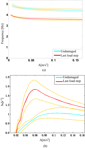
Figure 2. Instantaneous undamped natural frequency (a) and instantaneous damping coefficient h0(t) (b) along the amplitude of vibration [50].
Download figure:
Standard image High-resolution image3.2.2.2. Nonlinear damping parameter
It is acknowledged that tiny cracks cause little change in natural frequencies, to the extent that higher mode shapes are usually required to detect such cracks. In some circumstances, small cracks cause larger changes in damping, as reported in [134], a phenomenon that presents a new path for detecting slight damage using damping.
Zonta et al [134] conducted vibration tests on prestressed RC (PRC) hollow panels and observed that cracks in the PRC caused a non-viscous dissipative mechanism, making damping more sensitive to damage. They recognized the need for further research using damping for damage detection because additional effects such as other non-classical dissipative mechanisms must be considered. It is noted that the difficulties in accurate estimation of damping caused a scattering higher than the frequency. Franchetti et al [135] presented a damage detection method for PRC elements on the basis of free vibration tests of three precast PRC beams and nonlinear damping identification. The increase in the damage level appeared to cause growth in internal microcracks or concrete–steel debonds, resulting in increasing nonlinearity, and the authors proposed a quadratic damping model by a combination of viscous damping and a polynomial damping with the aim of describing the damping behavior of cracked RC structures. It was observed that the quadratic damping effectively represented the actual energy dissipation mechanism in PRC members associated with the different levels of damage. The quadratic damping factor is much more sensitive to the presence of damage than the viscous damping ratio, and thus can be effectively used for damage identification purposes. The technique described in this article is based on the analysis of a free vibration signal that limits applications because of the difficulty in obtaining a free vibration response of a structure.
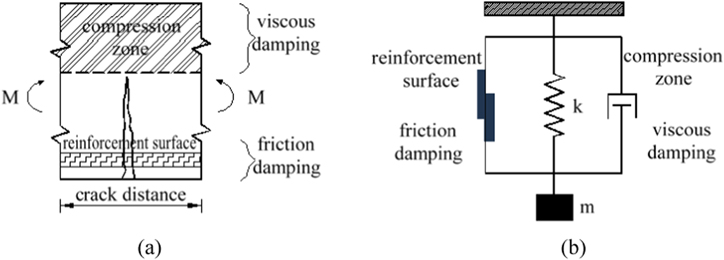
A baseline-free damage detection method for RC structures based on nonlinear damping analysis of ambient vibration data was developed in [52]. For a RC structure, figure 3 shows that the most significant dissipation mechanism in the cracked zone is friction damping, whereas in the compression zone it can be assumed that only viscous damping is present. The authors proposed a viscous–friction combined damping model and obtained the envelope of the free vibration response of a structure:

where  is the initial amplitude,
  the natural frequency,
  the viscous damping ratio, and
  the friction damping ratio. With application of the random decrement signature technique, the proposed method successfully identified, from its ambient vibration responses, nonlinear damping of a bridge associated with seismic damage. As the seismic damage became more severe, the viscous damping ratio
  decreased while the frictional damping ratio
  increased, providing information about the percentage of the total energy dissipated by each damping mechanism. It can be concluded that, with the evolution of damage, there is a shift of dissipated energy from a viscous mechanism to a friction mechanism. The nonlinear damping parameter
  can serve as a damage index. A significant advantage of this damage index is its baseline-free feature. The authors also compared the damage detection results with those obtained by stiffness-based methods, demonstrating a strong correlation between the increase in nonlinear damping and the decrease in structural stiffness associated with the increase in damage severity.
Figure 3. Cracked bending element (a) and corresponding model (b) [52].
Download figure:
Standard image High-resolution image
In general, there are several reasons to believe that damping is a possible damage indicator that is more sensitive to natural frequencies in RC structures. WT-based damping identification has the advantage of instantaneous damping estimation that can be used in damping-based damage detection. Unusually high damping would suggest the existence of more energy dissipation mechanisms than expected, indicating the possibility of damage in the structure. The use of nonlinear damping to indicate damage in RC concrete structures is more reliable because of its strong nonlinearity.
3.3. Damping-based damage detection in FR composites
In parallel with RC structures, FR composites have been widely used in a variety of infrastructure because of their high specific strength, specific stiffness, and tailorable properties [136]. FR composites have their particular failure modes, which may be in the form of matrix cracking, fiber breakage, delamination, etc [137]. Various investigations [125–129] of the effect of damage on damping of FR composites have demonstrated the considerable potential of damping to characterize damage. Damping itself can be used to indicate the presence of damage, while the combination of damping with some other traditional parameters such as modal strain energy, plane shape function (PSF), and natural frequencies, can be used to predict both the presence and the location of damage.
3.3.1. Damping with modal strain energy
Damping in composite fiber-reinforced plastic (CFRP) was found to be induced mostly by interfacial slip across the delamination and the tendency for mutual penetration between upper and lower surfaces in the delamination region [56]. In [56], a practical method was proposed for the location of delamination in CFRP plates by means of a combination of the change in modal damping and the distribution of modal strain energy, on the premise that modal damping only increases when the delaminated region is in the high region of the modal strain energy. The change in modal damping was calculated from the frequency response function produced by using the piezoelectric actuator and sensor to interrogate the intact and delaminated composite plates.
3.3.2. Damping with PSF
Montalvão et al [138] used modal damping factors as the main feature for localization of delamination damage in a CFRP plate. To indicate damage they proposed the damping damage indicator (DaDI) that could provide a geometrical probability indication of the damage location. The parameter DaDI is defined as:

where  denote coordinates,
  the mode, and the superscript
  stands for damage.
  represents the modal damping factor variation between the undamaged and damaged states of the structure, and can be obtained by

Because modal damping factors are global properties of a structure, providing no coordinate information, a generalized PSF is defined for mode  at a discretization node with coordinates
  as a function of the geometry of the structure to relate this global variation to the local coordinates of the structure:

where  and
and  are the strains in the x- and y-directions.
This method has the advantage that measurements can be taken with a reduced number of conventional sensors (theoretically, only one force and one response transducer are needed). However, the damping factors for both the damaged and the undamaged structures are required and the method is highly dependent on the amount and type of mode shapes used.
3.3.3. Damping with natural frequencies
A vibration-based technique that combined modal damping factors with natural frequencies as damage-sensitive features for locating impact damage in carbon FR laminates was developed by Montalvão et al [139, 140]. They established a damage index, the multi-parameter damage indicator (MuDI), formed by the weighted combination of two other indexes, the DaDI [138] and the frequency damage indicator, based on the assumption that a delamination in a composite laminate can lead to changes both in the natural frequencies and in the modal damping factors. The most likely zones of damage were found by MuDI, providing the possibility of subsequent inspection. It was observed that both an increase and a decrease in damping may depend on the damage type, a potential that poses some problems in application of the method, along with the uncertainty associated with damping identification.
In addition to the above studies that combined damping with traditional dynamic characteristics, Kyriazoglou et al [51] explored the use of the specific damping capacity (SDC) for damage detection and localization in composite laminates. The SDC is defined as

where  is the energy dissipated in one cycle and
  is the total energy stored in that cycle. The authors observed that the change in natural frequencies or flexural modulus may be used as a damage indicator in glass-fiber-reinforced plastic (GFRP) laminates, but the SDC is more sensitive to damage in CFRPs. Keye et al [141] developed a localization method of delamination in CFRPs based on damage-caused modal damping variations. They built a correlation of experimental and numerical damping factors acquired from measured frequency response data and a numerical damping model respectively through a modified modal assurance criterion. The numerical model that best fitted the experimental data yielded information as to the most probable damage location in the test structure. Because in practice the damage location is unknown, a whole set of damage locations must be simulated in the numerical model. The effectiveness of the method depends on the quality of the experimental data as well as the numerical simulations of damage. Kostka et al [53] identified in situ structural integrity of a smart structure–carbon FR epoxy composite plate based on revealing damage-dependent damping with an integrated actuating/sensing system. They conducted dynamic tests on intact and damaged specimens for characterization of damping changes caused by impact events and then developed a finite element model of the structure to determine the damping ratios for different sizes and locations of damaged regions. The deterministic decision trees describing the relation between online-measured damping and damage condition were determined. Kawiecki [142] presented the use of arrays of surface-bonded piezotransducers to determine damping characteristics of a tested structure for structural damage detection. Any array element could be utilized as an actuator, to generate an excitation signal sweeping the frequency scope of interest, and the vibration responses could be picked up either by the actuator, or by another transducer. The excitation and the response gave rise to the frequency transfer function, from which the modal damping was calculated. Structural damage was detected in terms of the relation that damage caused changes in damping, The ease of use and the repeatability of results obtained using piezotransducers outweighs traditional methods relying on accelerometers and impact hammers or shakers.
These studies reflect a new trend of using damping to characterize damage in FR composites, different from the traditional method of depicting damage relying on stiffness reduction of a structure. Notably, failure modes and damage patterns must be taken into account when using damping to characterize damage in FR composites because the damping mechanism in FR composites varies with different failure modes and damage patterns.
4. Factors influencing damping to characterize damage
Despite the efficiency and merits reported in various studies, the use of damping to characterize damage is still a topic under active development, an issue that is in progress but not yet as well resolved as natural frequencies and mode shapes. When addressing the positive aspects of damping in damage detection, one should note the factors that inhibit the capability of damping to characterize damage. The major factors include the uncertainty in the estimation of damping and certain operational factors. These influencing factors need to be clarified to expand the space for using damping in damage identification.
4.1. Uncertainty in damping estimation
Uncertainty in measured damping values from laboratory tests has been observed in several studies, especially when the damping is of low magnitude [143–145]. That uncertainty can be attributed to three aspects: (i) complexity in the damping mechanism usually creates uncertainty as to how to characterize the damping completely and accurately. Contributing to this effect is the fact that the damping estimate possibly accounts for only some components of damping, leaving one or two aspects of the real damping unconsidered. (ii) The absence of universal mathematical models makes it difficult to represent damping appropriately [58], especially in the situation in which the damping varies with the evolution of damage. (iii) Damping estimation methods can affect the quality of damping estimation. In the logarithmic decrement method, the sampling peak values used to estimate the damping ratio are not exactly the actual maximum values of a free vibration response, a factor that induces estimation error. In the half-power bandwidth method, the unclear peak of a frequency response usually elongates the bandwidth, as a result of which the damping ratio is often overestimated. In the wavelet-based time-frequency method, analyzing wavelets can affect the values of the estimated damping. To reduce uncertainty in damping estimation calls for further studies in revelation of the damping mechanism, development of a damping model, and the creation of robust damping estimation methods.
4.2. Interference of operational factors
Operational factors other than damage can induce changes in damping. Operational factors influencing the damping of unreinforced concrete include water and cement contents of the concrete, age of the concrete, and level of stress [119]. Lu et al [146] observed that damping was influenced by the displacement ductility of RC frames. Lazan's [49] research showed that damping was affected not only by material quality but also by stress distribution. Newmark et al [147] found that damping varied significantly with differences in working stress. Audenino et al [148] presented the theoretical relation between temperature increment and damping in metals. Littler [149] showed that an increase in wind speed caused an increase in damping. Damping is more likely than natural frequencies and mode shapes to change in response to noise. Otani et al [150] noted changes in damping with an increase in excitation level, despite low response amplitudes. To enhance the accuracy of damping estimation, a crucial measure should be taken to find ways of avoiding the influence of these operational factors. This requires full understanding of the mechanism of damping for a particular physical situation.
5. Recommended research directions
This study has overviewed the state-of-the-art and the state-of-the-practice of using damping to identify damage in a variety of infrastructure, with particular emphasis on RC structures and FR composites. The potential, feasibility, efficacy, and influential factors of employing damping to characterize damage have been surveyed comprehensively, and the mechanism of utilizing damping to characterize damage was elucidated thoroughly. Recognizing that the use of damping to identify structural damage is a research topic as yet unresolved, recommended research directions to advance this topic are summarized here.
- (i)Damping is somewhat more sensitive than natural frequencies and mode shapes to damage in certain situations. The distinctions of damping in portraying damage, different from natural frequencies and mode shapes, need to be further clarified.
- (ii)When damping is used to characterize damage, clarifying the mechanism of damping and creating a valid damping model are key components to obtain reliable results, but existing investigations into these components are inadequate.
- (iii)As an extension of damping ratio, the instantaneous damping coefficient is a distinctive feature of nonlinear damping, suited to portraying the evaluation of nonlinear structural damage. More viable analysis methods are highly desired for extracting the instantaneous damping coefficient.
- (iv)Damping aided by some other vibration features can provide a means of damage location. Strategies for combining damping with vibration features to produce more effective damage location methods are worthy of exploration.
- (v)The uncertainty of damping estimation and the interference of operational factors are the most significant components that hinder the use of damping to characterize damage. It is crucial to develop sophisticated methods that can estimate damping by effectively eliminating these obstructing factors.
- (vi)Wavelet-based time-frequency methods for damping estimation have primarily exhibited the merits of robustness to noise and feasibility in estimating nonlinear damping. A key step to advance such methods rests on resolving the outstanding issue of selecting optimal analyzing wavelets.
Acknowledgments
This work received partial support from the Key Natural Science Foundation of China (No.11132003), the Natural Science Foundations of China (No. 11172091), Qing Lan Project, and the Fundamental Research Funds for the Central Universities (Grant Nos. 2014B03914 and 2012B05814).