

Abstract
This article outlines an improved radial magnetorheological (MR) valve that the magnetic flux is guided into the annular gap. This novel design is a way to force the magnetic flux into unexposed effective region by changing the material properties of the valve, thus maximizing the effective area while without extending the flow path. Finite element modeling and analysis of the improved radial MR valve was carried out by ANSYS/Emag software, including achieving the changes of the magnetic flux density and yield stress along the fluid flow paths. Moreover, the experimental tests were also conducted to evaluate the pressure drop and response time characteristics, showing that the improved radial MR valve can output a lager pressure drop, which is superior to that of conventional radial MR valve under the same geometry conditions and electromagnetic parameters. In addition, the improved radial MR valve was adopted to control the single rod cylinder and double rod cylinder separately, and the dynamic performance of improved radial MR valve controlled cylinder system was also investigated. The test result show that the improved radial MR valve controlled cylinder system can generate a larger damping force, and the damping force can be continuously adjusted under the different applied currents.
Export citation and abstract BibTeX RIS
1. Introduction
Magnetorheological (MR) fluid is a smart material that can change its rheological properties continuously and reversibly in milliseconds with or without exerted magnetic fields [1]. This unique rheological property can make the MR fluid based valves needing no moving parts and having simple structure, fast response and high controllability. As the most basic hydraulic control devices, MR valve can be used as the key parts in many other devices such as MR dampers [2–4], shock absorbers [5–7], actuators [8, 9], mount [10] and brake [11]. Hence, a successful improvement of MR valve performance can significantly affect the development of other MR fluid based devices.
In general, a conventional MR valve consists of valve body, valve spool, excitation coil and a fluid flow path to form a closed magnetic circuit [12, 13]. Although the placement of coils and the detailed configuration of the flow path of each MR valve can be different depending on the specific design, the basic working principle is generally similar. In the MR valve, the magnetic field generated by the excitation coil can be controlled by varying the applied current, which result in the changes of the MR fluid rheological properties in the fluid flow path and furthermore control fluid flow resistance magnetically. Hence, the pressure drop of the valve is changed, such that the MR fluid flow can be slowed or even stopped.
In recent years the research of MR valves aims at achieving large pressure drops or fast responses by either designing a novel valve structure or optimizing the existed valve structure. Among them, there are three typical fluid flow paths which can be arranged geometrically to expose to the magnetic flux lines in MR valve, that is, the annular flow path, the radial flow path, and both the annular and radial flow paths.
The annular fluid flow path is the most used structures in the existed MR valve. Grunwald et al [14] developed an annular MR valve with single excitation coil, and the results indicated that the pressure drop was 1.5 MPa when the applied current was 4.5 A. Hu et al [15] designed an annular MR valve with double excitation coils, which can achieve a better pressure drop performance through the finite element analysis and experimental test verification. Kubik et al [16] presented an annular MR valve with three excitation coils, which is also used in an MR damper as a bypass valve. This MR valve can achieve a short response time and larger dynamic force range. However, most annular MR valves still have a lower pressure drop despite the extensive advancements for the excitation methods. The only way to improve the pressure drop is to increase the length of the fluid flow path, which is parallel to the valve body. Nevertheless, it is not preferable that it will enlarge the overall valve dimensions, as well as affect the valve performance such as weight and compact design.
Compared with the annular MR valve, the larger pressure drop can be obtained by radial MR valve due to the perpendicular fluid flow paths. Sahin et al firstly investigated the flow behavior of MR fluid through radial MR valve using CFD methods and experimental approaches [17], which provide a gudiance in the design and development of radial MR valve for practical applications. Gordaninejad and his coauthors [18, 19] designed and constructed a large-scale modular MRF bypass damper with a two-stage radial MR valve for seismic mitigation applications. This radial MR valve can provide a pressure drop of over 9.6 MPa at 5 A of input current, and the experimental results showed that the MRF bypass damper can provide a maximum damping force over 200 KN. Hu et al [20] developed a radial MR valve using a meandering fluid flow paths, which formed four effective radial resistance gaps. The simulation and experimental results showed that this new radial MR valve can provide an achievable pressure drop of more than 5.81 MPa, which proved the performance of the radial MR valve can be enhanced through the extension of effective areas using meandering flow path structure. Liao et al [21] designed and fabricated a multi-stage radial MR valve, and a MR damper based on this valve was also presented. The simulation and experimental results show that this MR damper is able to help overcome the problems of traditional MR damper with annular fluid flow paths. The advantage of radial MR valves is that the pressure drop can be increased by a multi-stage arrangement. However, the increment of channel radius or width of the radial MR valves will make the valve wider in the axial direction and further reduce the compactness of the valves.
The latest development for MR valves is a combination of annular and radial fluid flow paths, which makes full use of magnetic flux lines and has shown a significant promising performance over the annular MR valve and the radial MR valve. Wang and Ai [22, 23] proposed an MR valve by combing of both annular and radial fluid flow paths with the assumption that the magnetic flux densities at the annular and radial resistance gaps are identical. The results showed that the radial resistance gaps in the MR valve can provide more dominant contribution to a larger controllable range than those with annular resistance gaps. Imaduddin and Mazlan [24–27] developed a compact MR valve with multiplication of annular and radial resistance gaps. The simulation and experimental results revealed that this design could effectively increase the achievable pressure drop of the valve by more than 2.5 MPa while maintaining the dimension of valve outer diameter as 50 mm. Later, Imaduddin et al applieded this meandering type valve in an MR damper to form bypass MR damper, and the advantages of this configuration was validated using neuro-fuzzy control strategy [28]. Hu et al [29, 30] developed a compact annular-radial-orifice flow MR valve, which can adjust the width of the radial resistance gap. The experimental results showed that the pressure drop of this MR valve has significantly improved at the radial resistance gap of 0.5 mm. However, the novel combination of both annular and radial gap will cause a complicatedly structure in the MR valve and the resistance gap is easy to block.
As mentioned above, the performance of the valve with combination of radial and annular fluid flow paths was the best, and the valve with single annular fluid flow path was the worst in the case of the same dimension. However, although the valve with combination of radial and annular fluid flow paths can achieve the highest pressure drop, the multiple flow path structure is complicated and easy to block, leading to a larger valve dimension. Therefore, a new method which extends effective area by weaving the magnetic field into the unexposed flow path was proposed. It can achieve a greater pressure drop without extension the dimension or complex the structure. This concept has been demonstrated from previous MR brake work, in which the serpentine flux path method was applied to MR brakes [31]. Besides, Abdul Yasser Abd Fatah et al simulated the method using FEM Magnetics to observe the effect of the weaving steps and thickness of the non-magnetic material on the magnetic flux distribution and pressure drop change in the valve. However, they did not experimentally validate [32, 33].
In this paper, an improved radial MR valve that the magnetic flux is guided into the annular gap was developed. By adding parts and changing the material properties of bobbin in the conventional radial MR valve, both effective annular and radial fluid flow paths can be obtained simultaneously. Compared with the magnetic flux lines are distributed only in the radial flow path of conventional radial MR valve, the improved radial MR valve can increase the effective annular area by changing the magnetic field structure without enlarging the overall valve sizes. Then, the effect of the hybrid fluid flow can be achieved. At the same time, the finite element method (FEM) was used to investigate the magnetic flux distribution and the magnetic flux density of the valve. Moreover, an experimental test rig was set up to investigate the pressure drop and response time characteristics. Furthermore, the presented valve was used as a control unit in valve controlled cylinder system, and its dynamic performance were experimentally tested.
2. Design and development of the improved radial MR valve
2.1. Structure analysis of the improved radial MR valve
The structure of the improved radial MR valve is shown in figure 1. The magnetic disk, non-magnetic disk and non-magnetic ring are introduced to make the magnetic flux lines not only perpendicularly pass through the radial resistance gap, but also perpendicular to the annular resistance gap. Therefore, the improved radial MR valve can achieve the effects of conventional radial MR valve and the annular MR valve together.
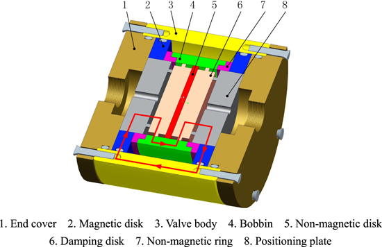
Figure 1. Schematic diagram of the improved radial MR valve.
Download figure:
Standard image High-resolution imageAs shown in figure 1, the fluid flow paths of the proposed radial MR valve are comprised of two annular flow paths, two radial flow paths and two orifice flow paths. In detail, the radial resistance gap is formed between the positioning disk and the damping disk as the effective gap, in which the flow direction of MR fluid is perpendicular to the direction of magnetic fluxes. The annular resistance gaps are looped between the damping disk and the bobbin. The magnetic fluxes in a conventional radial MR valve do not go through the annular resistance gap, which causes the annular gap out of the magnetic field. To make full use of the annular resistance gap, the conventional radial MR valve is modified with a non-magnetic disk and two non-magnetic rings, and the magnetic material of the bobbin is also replaced. It is noted that the non-magnetic is arranged to divide damping disk. In addition, two non-magnetic rings are arranged at both ends of the bobbin respectively such that the magnetic fluxes can be uniformly distributed in the annular resistance gap. The material properties of each part in figure 1 are shown in table 1.
Table 1. Material properties of the improved radial MR valve.
| Descriptions | Material | Magnetic properties |
|---|---|---|
| End over | 304 stainless steel | Non-magnetic |
| Magnetic disk | NO. 10 low-carbon steel | Magnetic |
| Valve body | NO. 10 low-carbon steel | Magnetic |
| Bobbin | NO. 10 low-carbon steel | Magnetic |
| Non-magnetic disk | 304 stainless steel | Non-magnetic |
| Damping disk | NO. 10 low-carbon steel | Magnetic |
| Non-magnetic ring | 304 stainless steel | Non-magnetic |
| Positioning plate | NO. 10 low-carbon steel | Magnetic |
Since the non-magnetic disk and the non-magnetic rings are non-permeable materials, the magnetic fluxes are bent to form a serpentine flux path. Consequently, it can be guided to the annular flow path in the valve as much as possible, which adds two effective annular resistance gaps. The circular through holes in the middle of the locating plate forms the orifice flow paths, and they are not intensively exposed to the magnetic field. Therefore, the influence of the magnetic field on the yield stress of the MR fluid in these areas can be neglected. By arranging different materials inside the valve to twist the magnetic flux paths under the applied currents, the improved radial MR valve can achieve the effects of both the radial and annular MR valve without expand the valve sizes. When a constant direct is applied to the excitation coil, the serpentine closed-loop circuits will be generated in the valve body, the magnetic disk, the radial flow resistance gap, the damping disk, the annular resistance gap, and the bobbin. Then, the intense magnetic fields will generate in both the radial and annular resistance gaps. Finally, a pressure drop between the inlet and outlet ports of the valve will be produced because of the yield stress in both the resistance gaps. Therefore, this pressure drop can be controlled by adjusting the applied current.
2.2. Magnetic circuit of the improved radial MR valve
Figure 2 shows the simplified magnetic circuit of the improved radial MR valve. According to the continuity principle of the magnetic flux, the magnetic flux density throughout its conduit is determined. It can be expressed as

where  is the magnetic flux density of the circuit,
  and
and  are the magnetic flux density of the MR fluid in the annular gap and radial gap, respectively; and
  is the magnetic flux density of the valve body, magnetic disks, positioning plates, bobbin and damping disk in the primary magnetic circuit.

Figure 2. The simplified magnetic circuit of the proposed radial MR valve.
Download figure:
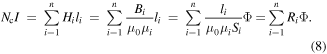
Standard image High-resolution imageThe magnetic circuit is deduced by applying the magnetic Kirchhoff's law, it is regarded as

where Nc is the number of turns of the excitation coil and I is the current applied to the excitation coil, Hi and li are the magnetic field intensity and the overall effective length in the ith link of the circuit, respectively.
On the other hand, the magnetic flux conservation rule based on Gauss's law can be givened as

where Bi is the magnetic flux density of the ith link, and Si is the cross sectional area of that link.
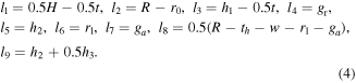
As shown in figure 2, the magnetic circuit is divided into nine sections. The effective length of each section of the path is expressed as follows:
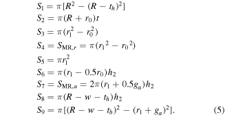
On the other hand, the cross-sectional area of the ith link in the magnetic flux path can be deduced by
Based on the electromagnetic theory, the magnetic flux density B in terms of the magnetic field intensity H can be approximately expressed as

where μ0 = 4π×10–7 T mA−1 is the magnetic permeability of free space, and μi is the relative magnetic permeability of magnetic materials.
Ri represents the magnetic resistance of the ith link in the magnetic flux path, the equation of Ri is deduced as

Therefore, the equation of magnetic Kirchhoff's law can be converted to
The magnetic flux density of each part of the magnetic circuit can be calculated by the following formula and respectively limited to the magnetization property of the used magnetic materials

where Bjsat is the saturated magnetic flux density of the corresponding material in the jth link.
According to equations (7) and (9), the magnetic flux density of MR fluid in the annular gap and radial gap can be obtained as follows

To improve the utilization of magnetic field and reduce the energy loss, the yield stress in the radial and annular resistance gaps of the improved radial MR valve should reach saturation at the same time. Therefore, it is necessary to ensure the magnetic flux density of the radial gap equal to that of the annular gap. From equation (3), it can be deduced that

As mentioned above, BMR,r is roughly equal to BMR,a, and SMR,r is also roughly equal to SMR,a. So the relationship of r1 and h2 can be determined according to equation (5).
Since the relative permeability of the MR fluid is much smaller than the relative permeability of the magnetic material, the magnetic resistance of the fluid at the effective flow path is much greater than that of other structures of MR valve. As shown in equations (4) and (7), the gap size is proportionally related to the magnetic resistance, so the gap size is a significant factor influencing the performance of MR valve. A larger change in the gap thickness will significantly increase the magnetic resistance and decrease the magnetic flux density, which decreases the pressure drop. However, The MR fluid will be difficult to pass through the resistance gap if the gap thickness is too small. In general, the reasonable gap thickness ranges from 0.5 and 1.0 mm [23]. Therefore, the thickness of radial and annular resistance gaps is set as 1.0 mm, and the radius r0 of orifice gap is assigned as 2 mm.
Finally, the size is determined by the comparison between theoretical calculation and simulation analysis. Table 2 summarizes the primary parameters of the proposed radial MR valve.
Table 2. Primary parameters of the improved radial MR valve.
| Parameters | Descriptions | Units | Values |
|---|---|---|---|
| η | Fluid viscosity without magnetic field | Pa s | 0.8 |
| ga | Annular gap size | mm | 1 |
| gr | Radial gap size | mm | 1 |
| th | Thickness of the valve body | mm | 8 |
| R | MR valve radius | mm | 46 |
| H | Length of the valve body | mm | 48 |
| w | Groove thickness | mm | 11.4 |
| t | Thickness of the magnetic disk | mm | 7.8 |
| r0 | Orifice radius | mm | 2 |
| r1 | Radius at the damping disc | mm | 18.3 |
| h1 | Length of the positioning plate | mm | 15 |
| h2 | Thickness of the damping disc | mm | 6.5 |
| h3 | Length of the non-magnetic disk | mm | 14 |
2.3. Mathematical model of pressure drop for the improved radial MR valve
As show in figure 3, there are two orifice gaps, two radial gaps and two annular gaps together in the improved radial MR valve. Hence, the pressure drop Δp can be represented as

where Δpo, Δpr, Δpa are the pressure drop through the orifice flow path, the radial flow path and the annular flow path, respectively.
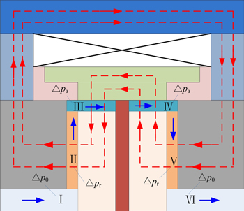
Figure 3. Flow paths classification of pressure drop in the proposed MR valve.
Download figure:
Standard image High-resolution imageThe pressure drop Δpo in the orifice resistance gap can be expressed as [22]

where q is system flow rate, and η is viscosity without magnetic field.
The pressure drop Δpr in the radial resistance gap can be defined as [23]
where Δpr−η is the pressure drop from the viscous properties of the fluid in the radial resistance gap, Δpr−τ is the pressure drop from the field dependent yield stress of the fluid in the radial resistance gap, τy1 is the variation of yield stress in the radial resistance gap with respect to an applied magnetic field, and c is the flow velocity profile coefficient whose value range is 1–3.
The pressure drop Δpa in the annular resistance gap can be calculated as [23]
where Δpa−η is the pressure drop from the viscous properties of the fluid in the annular resistance gap, Δpa−τ is the pressure drop from the field dependent yield stress of the fluid in the annular resistance gap, τy2 is the dynamic yield stress in the annular resistance gap that responds to an applied magnetic field.
By substituting equations (14)–(16) into equation (13), the pressure drop Δp of the improved radial MR valve can be obtained
As shown in equation (17), the pressure drop Δp contains five items. The first three items are the pressure drops from the viscous properties of the fluid which related to the system flow rate, and the later two items are the pressure drops from the field dependent yield stress of the fluid which are related to the applied magnetic fields.
3. Modeling and simulation of the improved radial MR valve
3.1. Magnetic properties of MR fluid and steel used in the improved radial MR valve
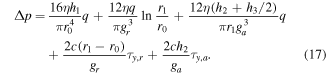
The MR fluid selected for the proposed MR valve is MRF-J01T which was provided by the Chongqing Instrument Material Research Institute in China, and its field dependent properties is depicted in figure 4 [34]. As shown in figure 4(a), the relation between the yield stress and magnetic flux density can be fitted using a polynomial equation in equation (18)


where a0, a1, a2 and a3 are polynomial coefficients that determined by the least-squares fitting of the changes of yield stress data as a function of magnetic flux density, here a0 = 0.0182 kPa, a1 = −48.4644 kPa T−1, a2 = 865.3901 kPa T−2 and a3 = −984.2742 kPa T−3.
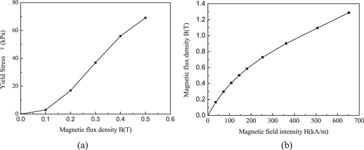
Figure 4. Specification of the MR fluid with the type MRF-J01T: (a) the variation of the yield stress τ and the magnetic flux density B, and (b) the variation of the magnetic flux density B and the magnetic field intensity H.
Download figure:
Standard image High-resolution imageThe steel material used in magnetic disk, valve body, bobbin, damping disk and positioning plate are NO.10 low cabon steel materials, and the relationship between the manegtic flux density and the magnetic field intensity of the used steel materal is shown in figure 5.

Figure 5. B–H curve of the No.10 steel material.
Download figure:
Standard image High-resolution image3.2. Simulation analysis using the FEM method
In order to simplify the calculation, a 2D axis-symmetric finite element model of the improved radial MR valve is built by using ANSYS/Emag software, which is shown in figure 6. The improved radial MR valve is divided into four areas in terms of material properties, namely the non-magnetic material, the coil, the magnetic material and the MR fluid. The permeability of the magnetic material in the valve is assumed to the B–H curve of No. 10 steel shown in figure 5. The highest magnetic flux density is up to 2.4 T when the applied magnetic field intensity exceeds 320 kA m−1, and the relative permeability of the non-magnetic material is assumed to be 1. The excitation coil is made from copper wire with a relative permeability of 1 and the number of turns is calculated as 743. The current density in the excitation coil is set 2.51 A mm−2 when the applied current is 2.0 A.

Figure 6. 2D finite element model of the improved radial MR valve.
Download figure:
Standard image High-resolution imageFigure 7 shows the magnetic flux distribution of the improved radial MR valve at the applied current of 1.0 A. The magnetic flux line vertically pass through the two radial resistance gaps, it is also perpendicularly pass through the annular resistance gap with the effort of the non-magnetic disk and non-magnetic ring. To investigate the distribution of the magnetic flux density clearly, the path S1, S2, S3 and S4 along the fluid flow paths are defined separately, as shown in figure 7.
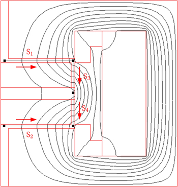
Figure 7. Magnetic flux density distribution and defined paths.
Download figure:
Standard image High-resolution imageFigure 8 shows the magnetic flux density vector of the presented valve, it can be observed that the magnetic flux lines have been twisted in the middle of the valve spool. Figure 9 shows the magnetic flux density contour. Different color distributions represent different values of the magnetic flux densities in different regions. The magnetic flux densities in the non-magnetic ring and non-magnetic disk are close to 0 T. The color distributions in the radial gap and the annular gap are very similar, the magnetic flux densities in both gaps are identical, and the average values are 0.44 T.
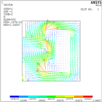
Figure 8. Magnetic flux density vector of the improved radial MR valve.
Download figure:
Standard image High-resolution image
Figure 9. Magnetic flux density contour of the improved radial MR valve.
Download figure:
Standard image High-resolution imageFigure 10 shows the magnetic flux density along with the defined fluid flow paths shown in figure 7. The region S3 and S4 can achieve higher magnetic flux density while that of the conventional radial MR valve is almost zero. Moreover, the magnetic flux density increases both in the radial and annular resistance gaps by the augmentation of current input to the excitation coil. The peak value of the magnetic flux density at the radial region S1 and S2 is slightly lower than at the annular region S3 and S4. However, the difference is not obvious. Therefore, the method of serpentine flux paths in the proposed valve can achieve a high utilization of the magnetic flux density. In addition, the magnetic flux densities in the radial and annular fluid flow paths were focused on the middle region, and they decrease gradually at the both end of the defined paths. Furthermore, the magnetic flux densities at the annular region S3 and S4 which are close to the non-magnetic disk decreases rapidly until zero, exhibiting that the magnetic properties of the valve are good. The change of magnetic flux density at radial fluid flow path S1 is equal to the radial fluid flow path S2. Meanwhile, the change of magnetic flux density at annular fluid flow path S3 is equal to the annular fluid flow path S4. As a consequence, the average magnetic flux density at the arbitrarily resistance gaps can be selected to analyze the MR rheological performance changes, such as S1 and S3.

Figure 10. Magnetic flux density along the defined paths under the different applied currents.
Download figure:
Standard image High-resolution imageThe yield stress value can be predicted by the magnetic flux density value shown in figure 11. The change of the yield stress variation is similar to the change of the flux density variation. The peak values of yield stress at the annular region S3 and S4 are slightly higher than those of the radial region S1 and S2. In addition, the yield stress at the radial and annular resistance gap are close, which remain almost 70 kPa at the current of 1.5 A. It indicates that the yield stress of MR fluid almost reaches the saturation under this applied current.

Figure 11. Changes of yield stress along the fluid flow path under the different applied currents.
Download figure:
Standard image High-resolution imageFigure 12 shows the average magnetic flux density and the corresponding yield stress variations of the radial resistance gaps S1 and the annular resistance gap S3 under different applied currents. The average magnetic flux density increases as the applied current increases. In addition, the higher average magnetic flux density was observed in the radial gap S1 than the annular gap S3 under same applied current. The average magnetic flux density in the radial fluid flow path is 0.52 T and in the annular fluid flow path is 0.44 T when the current applied to the excitation coil is 1.6 A. However, the deviation of the magnetic flux density in the radial and annular resistance gap is small, which shows the high utilization of the magnetic flux density for the improved radial MR valve.
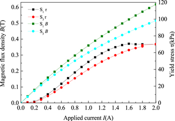
Figure 12. Flux density and yield stress under different applied currents.
Download figure:
Standard image High-resolution imageFigure 12 also shows the yield stress for each corresponding current input. The yield stress has a consistent increase with the increment of current input to the excitation coil on the initial stage. When the current increases to 1.6 A, the yield stress almost reaches the saturation value of about 70 kPa. The corresponding average magnetic flux density is 0.53 T. Therefore, the yield stress value is kept constant at 70 kPa once the average magnetic flux density value in the effective gap exceeding 0.53 T. Though the yield stress in annular gap S3 is not saturated when the applied current is 1.8 A, it is close to the saturation value of about 67 kPa.
Since there are variations of yield stress value in each gap, the pressure drops generated from each of the gaps will be different. The estimation results of the pressure drop with the variation of the current input are shown in figure 13. The rate of increment of pressure drops of the radial gap is faster than that of the annular gap with the increasing of applied current. It means that the radial gaps provide more dominant contribution to the pressure drop of the valve than that of the annular gaps. In addition, the pressure drop of radial gap reaches saturation at first and the value is 4630 kPa at the applied current of 1.6 A, while the pressure of annular gaps still not reach saturation at the applied of 1.8 A and the maximum pressure drop is approximately 1760 kPa. The pressure drop of orifice gap is always 35 kPa as the applied currents change. Therefore, the total pressure drop of the proposed valve at applied current of 1.8 A is about 6.425 MPa. By observing figure 13(b), the contribution of the annular gap, the radial gap and the orifice gap to the pressure drop of the valve are around 71.23%, 28.22% and 0.55%, respectively.

Figure 13. Simulation of pressure drop of the improved radial MR valve: (a) the pressure drop in variety gaps under different currents, and (b) contribution of each gaps to pressure drop at saturated magnetic density.
Download figure:
Standard image High-resolution image4. Performance analysis of the improved radial MR valve
4.1. Prototype and test rig setup of the improved radial MR valve
To validate the dynamic performance of the improved radial MR valve, the prototype was fabricated as shown in figure 14, and the experimental test rig was also built up, which is shown in figure 15. A motor driven gear pump was applied as a power unit. Pressure sensor (a) and (b) were used to measure the inlet and outlet pressure of the MR valve, respectively. A relief valve (a) was used as a safety valve to protect the hydraulic system, and a relief valve (b) was adopted to simulate the load cases in the hydraulic control system. The DC power (a) was used to supply power to the two pressure sensors, and the DC power (b) was applied to supply power for the excitation coil of the radial MR valve. A data acquisition board was used to capture the pressures value. A host computer was used to monitor the relevant test parameters of the hydraulic control system in real time [30].
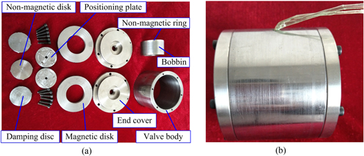
Figure 14. Prototype of the improved radial MR valve: (a) manufactured component, and (b) assembly valve.
Download figure:
Standard image High-resolution image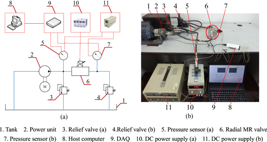
Figure 15. Experimental test rig for the valve performance: (a) schematic of the test system, and (b) paragraph of the test system.
Download figure:
Standard image High-resolution image4.2. Experimental results analysis
4.2.1. Pressure drop performance analysis of improved radial MR Valve
In the tests, three typical load cases were selected by adjusting the outside valve knob of the relief valve (b). The load case 1 was defined by adjusting the outside valve knob one clockwise circle at the initial state, and the load case 2 was defined by adjusting the outside valve knob two clockwise circles at the initial state, and the load case 3 was defined by adjusting the outside valve knob three clockwise circles at the initial state.
Figure 16 shows the experimental pressure of the MR valve at load case 1 over the range of current input between 0 and 2.0 A with a 0.2 A interval. The inlet port pressure and the pressure drop increase steadily as the applied currents increase until saturation is reached at a maximum pressure drop of about 4.2 MPa pertaining to the current of 1.8 A. In addition, the outlet port pressure is basically kept constant at a value of 500 kPa due to the back pressure provided by the relief valve (b). However, the outlet port pressure shows a slight fluctuation because the gears in the gear pump were worn out due to the long operating time and the abrasive nature of the MR fluid. Little air mixed into the MR fluid when the fluid was back to cylinder may also cause this problem.
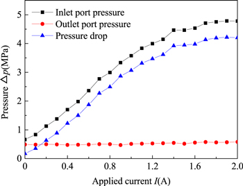
Figure 16. Pressure change under applied currents at load case 1.
Download figure:
Standard image High-resolution imageFigure 17 shows the effect of the load cases on the pressure drop of the valve. The relationship between the pressure drop and the current input under the three load cases is almost coincident, indicating that the pressure drop is not affected by the load cases basically. It is only related to the applied currents, which show that the pressure drop of the improved radial MR valve is stable. Therefore, a bypass-type MR damper can be constituted by the radial MR valve installing in the hydraulic cylinder with a bypass duct, which control the movement of the piston by the generated pressure drop from the MR valve. The bypass-type MR damper has advantages of simplicity in structure design and assembly and convenience in maintenance. Besides, the design of the improved radial MR valve can generate larger pressure drop. These advantages further effectively expand the adjustable range of the damping force, so that the damper can be used in a narrow and compact volume under different load conditions.

Figure 17. The variation of pressure drop under three typical load cases.
Download figure:
Standard image High-resolution imageFigure 18 shows the comparison between the experimental pressure drop and the simulated pressure drop with various current inputs and the constant flow rate 4 l min−1. The simulated pressure drop is slightly lower than that of experimental tests when the applied current is less than 0.5 A. The possible reason is that the viscous pressure drop provides more dominant contribution in the low current input condition, while the shear thickening effect of the MR fluid is not considered in the simulation based on the Bingham model. However, when the applied current is greater than 0.5 A, the experimental pressure drop is lower than the simulation value. The possible reason is that the pressure drop induced by the yield stress plays a dominated role with the increament of input current. The relationship between the yield stress and the magnetic flux density is obtained under the assumption that the magnetic particles in the MR fluid form a single-chain structure. However, the structure formed by the magnetic field is not a single-chain structure, but a column-like structure. Therefore, the saturated yield stress will be smaller in the actual experiment tests. On the other hand, the simulation results are obtained in ideal situations and only consider the proposed MR valve itself, but the experimental pressure drop values are measured in the whole test system, which consist of power unit, hydraulic pipe, MR valve, and so on. The abrasion of gear pump, the resistance of hydraulic pipe and the sedimentation of MR fluid will affect the experimental results, which are not considered in the simulation. Moreover, the leakages of the magnetic flux will reduce the magnetic flux density in the effective area to some extent, which also makes the experimental pressure drop smaller than the simulated pressure drop. Based on above possible reasons, the maximum pressure drop in experimental tests is lower than that in simulation when the applied current is bigger than the 0.5 A. Nevertheless, the change trend of pressure drop from experiment measurement is in accordance with the predicted one from FEM.
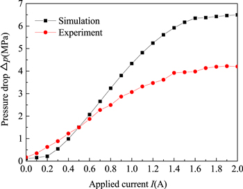
Figure 18. Pressure drop comparison of simulated result and experimental result.
Download figure:
Standard image High-resolution imageFigure 19 shows the comparison of the pressure drops of the improved radial MR valve at flow rates of 4 l min−1 and 10 l min−1, respectively. In the test, two fixed gear pumps were used to investigate the change of pressure drop separately. The flow rate of the first fixed gear pump is 4 l min−1, and the other is 10 l min−1. Observing figure 19, it can be seen that the measured pressure drop at the 10 l min−1 flow rate is slightly bigger than that at the 4 l min−1 flow rate. In addition, the pressure drop increases gradually when the current increases from 0 to 1.8 A.
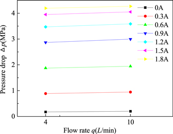
Figure 19. Pressure drop comparison under applied currents with various flow rate.
Download figure:
Standard image High-resolution image4.2.2. Pressure drop comparison of improved and conventional radial MR valve
To confirm that the improved radial MR valve can achieve better pressure drop performance, a conventional radial MR valve with same geometry conditions and electromagnetic parameters was fabricated, as shown in the figure 20, and its pressure drop has been measured on the test rig too. Figure 21 shows the experimental pressure of the conventional MR valve at load case 1 when the current input was applied from 0 to 2.0 A with a 0.2 A interval. The inlet port pressure and the pressure drop increase steadily as the applied currents increase. When the current was applied at 1.4 A, the pressure was saturated and the maximum pressure drop reached 3.2 MPa.

Figure 20. Schematic diagram and prototype of the conventional radial MR valve: (a) schematic diagram, (b) manufactured component, and (c) assembly valve.
Download figure:
Standard image High-resolution image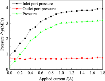
Figure 21. Pressure change under applied currents of conventional MR valve at load case 1.
Download figure:
Standard image High-resolution imageFigure 22 shows the comparison of pressure drop between the improved and conventional radial MR valve under different applied currents. The pressure drop of the improved valve is lower than the conventional valve at first. When the applied current is greater than 0.9 A, the pressure drop of the conventional valve is increase at a slower rate, while the pressure drop of improved valve continue to increase rapidly. At the same time, the pressure drop of the improved valve is greater than the conventional valve. Moreover, the pressure drop of conventional valve reaches saturation at the applied current of 1.2 A, and the maximum pressure drop is approximately 3.2 MPa. The pressure drop of improved valve reaches saturation at the applied current of 1.8 A, and the maximum pressure drop is 4.2 MPa. It can be seen that the pressure drop of the improved radial MR valve is higher than that of the conventional radial MR valve with a value of 1 MPa when they all reach the saturation value. The test results show that the pressure drop of the improved radial MR valve can increase by 31.25% than that of conventional valve, which show a better control performance.
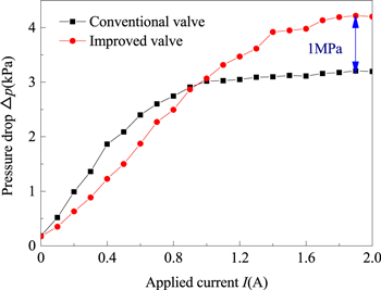
Figure 22. Pressure drop comparison of improved and conventional radial MR valve.
Download figure:
Standard image High-resolution image4.2.3. Response time analysis of the improved radial MR valve
Although the performance of MR valve is mainly determined by the pressure drop, the response time is also an important factor affecting its dynamic performance [35]. Therefore, the response time of the pressure drop was experimentally investigated too. In order to collect test data facilitately, the response time of the hydraulic test system is regarded as that of MR valve. Due to the influence of the hydraulic pipe and the response time of motor driven pump, the measured value will be slightly larger than the actual response time of MR valve, but it still can reflect the response characteristics of MR valve to some extent. In the system, the response performance consists of the rising response time and falling response time. The rising response time is defined as the time required for the pressure drop of the system to rise from its initial state to two thirds of its saturated value after the current is applied. Conversely, the falling response time is defined as the time required for the pressure drop of the system to fall from its initial saturated state to one third of its saturated value after the current is applied [35].
Figure 23 shows the response performance of the improved radial MR valve under different applied currents. The rising pressure response time is 98 ms at the applied current of 0.4 A while the rising pressure response time is up to 204 ms at 1.6 A. It can be concluded that the rising response time increases with increasing applied current since the greater the current is applied, the greater the pressure drop that needs to be established. Additionally, the falling response time of pressure drop under different currents is close to about 107 ms, which shows that the falling response time is almost independent of the applied currents. According to reference [35], it is shown that the rising response time of pressure for the annular and radial MR valve at the 3 mm resistance gap is 110 ms and 68 ms, and the falling response time of pressure for the annular and radial MR valve at the 3 mm resistance gap is 160 ms and 60 ms, respectively. In our works, the proposed MR valve consists of radial and annular resistance gaps simultaneously, and both of the thicknesses are 1 mm. The rising and falling response time of the proposed MR valve are between 98 and 204 ms, which also shows a good response characteristic to some extent compared with the study in [35].
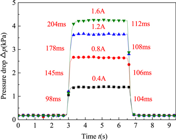
Figure 23. Response time of pressure drop under different applied currents.
Download figure:
Standard image High-resolution imageFigure 24 shows the response performance of the improved radial MR valve under different flow rates with respect to the applied currents of 0.4 A, 0.8 A and 1.2 A, respectively. From the figure, no matter how much current is applied, the rising response time of the flow rate of 4 and 10 l min−1 is basically equal, as well as the falling time. However, the response time at various flow rates is slightly different, both within 2 ms, which indicates the response time is nearly independent of the flow rate.

Figure 24. Response time of pressure drop under varying flow rates.
Download figure:
Standard image High-resolution image5. Performance analysis of the improved radial MR valve controlled single rod cylinder system
5.1. Prototype of the improved radial MR valve controlled single rod cylinder system
In order to broaden the industrial applications of MR valve, a MR valve controlled cylinder system which used the improved radial MR valve as its control unit was established. This arrangement solves the problem of difficulties in maintenance and disassembly of traditional MR damper. Moreover, the improved radial MR valve controlled cylinder system can increase the damping force without enlarge the dimension of the MR damper, and the system can achieve different performance by replacing different MR valves.
Figure 25 shows the prototype of improved radial MR valve controlled single rod cylinder system, which consists of an improved radial MR valve, a single rod hydraulic cylinder, an accumulator and hydraulic pipes. The improved radial MR valve, hydraulic cylinder and hydraulic pipes are filled with MR fluids. The piston rod is moving to and fro in the single rod hydraulic cylinder, which makes the MR fluid flows through the improved radial MR valve. Hence, the controllable pressure drop produces in the inlet and outlet of the MR valve when the current applies to the excitation coil, then the system can output controllable damping force. Since effective working area of the stretching chamber and the compression chamber is not equal in the single rod hydraulic cylinder, an accumulator is used to compensate the volume change.
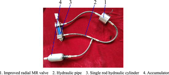
Figure 25. Prototype of improved radial MR valve controlled single rod cylinder system.
Download figure:
Standard image High-resolution image5.2. Experimental test rig setup
As shown in figure 26, an experimental test rig was established to validate the dynamic performance of the improved radial MR valve controlled cylinder system. An INSTRON fatigue test machine provides vibration excitation with different frequencies and displacements for valve controlled cylinder system. The lower end of the hydraulic cylinder is fixed on the fixture of fatigue test machine, and the upper end is connected with the power rod and force transducer. A DC power supply is used to supply power to the excitation coil of the valve. A host computer was used to monitor the relevant test parameters of the experiment system in real time.
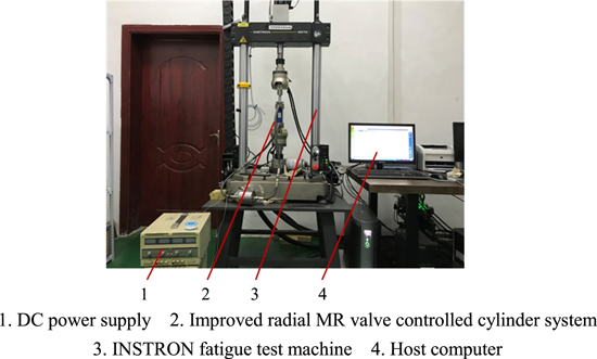
Figure 26. Experimental test rig of improved radial MR valve controlled cylinder system.
Download figure:
Standard image High-resolution image5.3. Analysis of the dynamic performance
Figure 27 shows the relationship between the damping force of the presented system and piston displacement of the hydraulic cylinder under different currents. The upper half of the curve represent damping force of the stretching stroke, while the lower half of the curve represents damping force of the compression stroke. Observing figure 27, the damping forces of both the stretching stroke and the compression stroke increase by increasing applied current, the reason is that the pressure drop of the MR valve increases as the current increases. The compression damping force is always greater than the stretching damping force as the effective area of the compression chamber in the single rod cylinder is larger than that of the stretching chamber. The maximum compression damping force is up to 5.8 kN and the maximum stretching damping force is up to 4.2 kN when the applied current is 1.25 A. The increase trend of the damping force is first rapidly and then slowly, which is coincide with the trend of pressure drop of the improved radial MR valve shown in figure 16. The curve of damping force is not full, of which both the stretch and compression stroke have a slight missing. It is explained that a small amount of air was mixed in when the MR fluid is injected into the system.
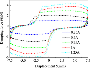
Figure 27. Variation of the damping force pertaining to displacement under different currents.
Download figure:
Standard image High-resolution imageFigure 28 shows the variation of the damping force of the proposed valve controlled cylinder system pertaining to the piston displacement of the hydraulic cylinder under different amplitudes. This damping force increases as the amplitudes increases, and the increase is small. Figure 29 shows the variation of the damping force of proposed valve controlled cylinder system pertaining to the piston displacement of the hydraulic cylinder under different frequencies. The damping force also increased slightly with frequency. The possible reason is that the pressure drop of MR valve consists of viscous pressure drop related to the system flow rate and yield pressure drop related to the applied current in terms of equation (17). The increases of amplitudes and frequencies of piston rod increase the flow rate of MR fluid in the system, leading to the enlargement of the viscous pressure drop. The effects of piston velocity on the damping force are little, and the system can output stable damping forces in a variety of operating conditions.
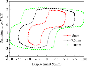
Figure 28. Variation of the damping force pertaining to displacement under different amplitudes.
Download figure:
Standard image High-resolution image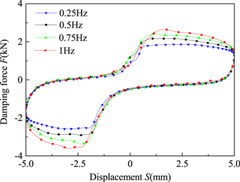
Figure 29. Variation of the damping force pertaining to displacement under different frequencies.
Download figure:
Standard image High-resolution image6. Performance analysis of the improved radial MR valve controlled double rod cylinder system
6.1. Prototype of the improved radial MR valve controlled double rod cylinder system
In order to further explore the application of the improved radial MR valve in different structural hydraulic cylinders, an improved radial MR valve controlled double rod cylinder system was proposed and established as shown in figure 30. It consists of an improved radial MR valve and a double rod hydraulic cylinder. Unlike the improved radial MR valve controlled single rod cylinder system, there is no accumulator in the MR valve controlled double rod cylinder system since the effective working area of the compression chamber is equal to that of the stretching chamber.
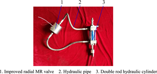
Figure 30. Prototype of improved radial MR valve controlled double rod cylinder system.
Download figure:
Standard image High-resolution image6.2. Analysis of the dynamic performance
Figure 31 shows the variation of the damping force of the MR valve controlled double rod cylinder system pertaining to the piston displacement of the hydraulic cylinder at different currents. The damping forces both the stretching stroke and the compression stroke increase with the increasing of applied current, which coincides with figure 27. Conversely, the compression damping force is always equal to the stretching damping force because the effective working area of the compression chamber of the double hydraulic cylinder is equal to that of the stretching chamber. The maximum damping force is close to 3.9 kN. The curve of damping force is not full as well.

Figure 31. Variation of the damping force pertaining to displacement under different currents.
Download figure:
Standard image High-resolution imageFigures 32 and 33 show the variation of the damping force of the MR valve controlled double rod cylinder system pertaining to the piston displacement of the hydraulic cylinder under different amplitudes and different frequencies, respectively. The damping force increases slightly with the increasing of frequencies or amplitudes, which agrees with the trend of the valve controlled single rod cylinder system.
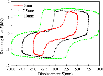
Figure 32. Variation of the damping force pertaining to displacement under different amplitudes.
Download figure:
Standard image High-resolution image
Figure 33. Variation of the damping force pertaining to displacement under different frequencies.
Download figure:
Standard image High-resolution image
7. Conclusion
In this paper, an improved radial MR valve was developed, designed and fabricated. This valve twists the magnetic flux path into unexposed annular gap by adding parts and changing the material properties of the conventional radial MR valve, and this design is described as an effort to achieve the effects of both the radial and annular MR valves without expanding the valve dimension or the flow path length. A better dynamic performance is obtained by the verifications of the FEM analysis, numerical simulations and experimental tests. The maximum pressure drop can reach 4.2 MPa, which is larger than that of conventional radial MR valve, which is 3.2 MPa. The response time of the improved radial MR valve is average of 150 ms at the applied current of 1.2 A, which proves that the pressure drop of this developed MR valve can established quickly. Meanwhile, an improved radial MR valve controlled cylinder system was established and tested. The damping force of the proposed system can be continuously adjusted under different applied currents, and the valve controlled cylinder system can achieve different dynamic performances by replacing the different type of hydraulic cylinder, such as the single rod and double rod hydraulic cylinder. The maximum damping force of the proposed MR valve controlled single rod cylinder system can reach 5.8 kN and that of the proposed MR valve controlled double rod cylinder system can reach 3.9 kN. Furthermore, the effect of piston velocity on the damping force is little, and the system can output stable damping forces in a variety of operating conditions.
Acknowledgments
This research was financially supported by the National Natural Science Foundation of China (Nos. 51765016, 51475165, 11462004), the Jiangxi Provincial Foundation for Leaders of Academic and Disciplines in Science (No. 20162BCB22019), and 5511 Science and Technology Innovation Talent Project of Jiangxi Province (No. 20165BCB18011).
Declaration of conflicting interest
The authors declare no conflicts of interest.