

Abstract
This paper aims to investigate the effect of temperature on the transmission characteristics of high-torque magnetorheological (MR) brakes by theoretically analyzing a disc brake, the pressure characteristics of the magnetorheological fluid (MRF) in axial, and the heat dissipation of an MR brake. A high-torque squeezing MRF brake with a water cooling method for heat dissipation is designed and a temperature-torque performance experimental system is established to conduct the experiments. The experimental results indicate that the high-torque squeezing MRF brake exhibits workable pressure characteristics. Meanwhile, the braking torque presents a variation trend that is initially increasing then decreasing when the temperature increases from 25 °C to 150 °C. The magnitude of decrease is approximately 210 N m, which decreases from 1800 to 1590 N m. Moreover, the temperature of the MRF presents an almost linear increase at different slip powers and the rate of temperature rise increases with an increase in slip power. The findings of this study prove that an effective cooling method can be vital to the stable operation of the high-torque MR brakes.
Export citation and abstract BibTeX RIS

Original content from this work may be used under the terms of the Creative Commons Attribution 3.0 licence. Any further distribution of this work must maintain attribution to the author(s) and the title of the work, journal citation and DOI.
1. Introduction
A magnetorheological fluid (MRF) is an intelligent material, whose viscosity and rheological properties drastically change under the action of an external magnetic field [1–6]. It mainly consists of three phases: soft magnetic particles as the dispersed phase, carrier fluid used as the continuous phase, and added stabilizers, antioxidants, thixotropic agents and lubricant additives used as surfactant additives to improve the performance of MRF [7–12]. Without a magnetic field, the MRF is characterized as a Newtonian fluid. However, under the action of an applied magnetic field, it can rapidly (within milliseconds) transform from a free-flowing liquid into a semi-solid or solid. Its viscosity then drastically increases with the loss of fluidity, which is the behavioral characteristic of a Bingham body and presents a controllable yield strength [13–16]. Moreover, these transformations are reversible and rapid. MRFs are widely used in machinery, construction, automobile and other fields because of these special properties [17–22].
Currently, high-torque and high-power mechanical devices are being developed with the advancement of transmission technology. However, current research and applications of magnetorheological (MR) transmission technology are still focused on low-torque and low-power devices, which is due to the low-torque and low-power density of MRF. One of the primary reasons is the high heat which is generated during the operation process, and the heat would affect the transmission performance and transmission accuracy of MR devices.
In this paper, a high-torque squeezing MRF brake with a water cooling method for heat dissipation is designed to address these challenging issues and expand the applications of MRFs in high-torque and high-power devices. A temperature-torque performance experimental system is also established to study the effect of temperature on the transmission characteristics of high-torque MR brakes.
2. Literature review
2.1. Effect of temperature on the transmission characteristics
In recent years, researchers have conducted several relevant studies on the effect of temperature on the transmission characteristics of MR devices. Chen et al [23] experimentally studied the effect of temperature on the transmission performance of the MRF and found that the temperature clearly influenced the characteristics of MR transmission (i.e. particularly, the effect would be relatively pronounced once the temperature was higher than 100 °C). Chen et al [24] experimentally studied the effect of temperature on the MRF performance, and the experiments indicated that the shear yield stress decreased with temperature. The yield stress decreased by 15% compared with the room temperature when the temperature was 220 °C. McKee et al [25] experimentally studied the effect of temperature on the performance characteristics of a compressible MR suspension system and found that both the stiffness and energy dissipation decreased with an increase in the temperature of the MRF. Saravanakumar et al [26] analyzed and tested the stiffness and damping characteristics of an MRF and found that they decreased with temperature in an MR squeezing film damper. Weiss et al [27] experimentally studied the effect of temperature on an MR-100 MRF. The results indicated that the dynamic yield stress and viscous resistance decreased by 10% and 95%, respectively, when the temperature increased from –40 °C to 150 °C. Moreover, the damping force in the corresponding MR damper decreased by 18%. Yang [28] found that the compressive damping force and tensile damping force decreased by 15% and 25%, respectively, when the temperature of the MRF increased to 180 °F. Furthermore, the decrease in the damping force was related to the thermal expansion of the MRF. Wiehe et al [29] experimentally studied the influence of temperature on the durability of the MRF, and the results indicated that the increase in temperature had an adverse effect on the durability of the MRF, which could cause a significant attenuation of the transmission torque. Gordaninejad et al [30] established a thermal analysis model of an MR damper and tested the relationship between the temperature and the damping force. The results indicated that the increase in temperature could lead to a sharp decrease in the damping force. Sahin [31] experimentally studied the effect of temperature on the transmission characteristics of an MR damper and found that the temperature could affect the magnitude of the damping force, which should be considered in the design stage. Larrecq [32] studied the relationship between the temperature and the damper force in an MR damper by numerical calculation, and the results showed that the damping force exhibited a linear decrease trend when the temperature rose from 80 to 200 °F. Wang et al [33] experimentally studied the effect of temperature on an MR clutch and found that the temperature could lead to a reduction in both the viscous torque and the total output torque.
2.2. Discussion
Our review of the abovementioned research clearly indicates that temperature has a significant influence on the transmission performance and transmission accuracy of MR devices. However, current research on the effect of temperature on the transmission characteristics of MR devices is still focused on low torque and low power, most of which tend to be qualitative. These problems have not yet been addressed until now. Continuing from a past study on the effect of temperature on the transmission characteristics of high-torque MR brakes, further research is performed herein to address these problems.
3. Theoretical basis and experimental devices
3.1. Theoretical basis of disc brake
A double disk-type transmission method is applied to the designed high-torque squeezing MRF brake to guarantee better stability and agility in the working process. Figure 1 illustrates the working principle of the disc squeezing MRF brake. MRF is filled between the driving disc and the brake disc, of which the width and radius are  and R, respectively. The rotation speeds of the driving disc and the brake disc are ω and 0, respectively.
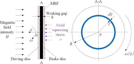
Figure 1. Working principle of the disc squeezing MRF brake.
Download figure:
Standard image High-resolution imageThe MRF rapidly changes from a Newtonian fluid into a Bingham fluid when an external magnetic field is applied. The shear stress  and the shear strain rate
  can be expressed as follows [34]:

where  and
and  are the static yield stress and the kinematic viscosity of the MRF, respectively.
The shear strain rate anywhere on the circular ring is:

Hence, the braking torque T caused by the whole working area can be expressed as follows:
3.2. Pressure effect analysis of MRF in axial
An axial squeezing MRF method is applied to the designed high-torque squeezing MRF brake to improve the braking torque and better reflect the high-torque characteristics in our experiments [35–37]. Figure 2 shows the stress analysis of magnetic particles in one particle chain before and after being squeezed under the action of an applied magnetic field. Without the squeezing action, the static magnetic stress between two particles is  then the
  becomes
  under the external squeezing action. Based on Coulomb's law, the static magnetic stress
  can be expressed as follows:

where  is Coulomb's constant;
  is the center distance between compressed magnetic particles, which is equal to
 is the radius of a magnetic particle,
  is the distance of two particles under the condition of without squeezing,
  is the displacement of a particle under the external squeezing action and
  is the magnetization intensity of a magnetic particle.

Figure 2. Stress diagram of a magnetic particle.
Download figure:
Standard image High-resolution imageWhen shearing action acts on MRF, the particle chains begin to tilt to a certain angle  along the direction of the shearing action, as shown in figure 3. The corresponding center distance between magnetic particles is
  and the stress acting on the magnetic particles in the horizontal direction can be expressed as follows:

Hence, the shear stress of the entire MRF can be expressed as follows:
where N is the number of magnetic chains.

Figure 3 .Schematic of the shear stress.
Download figure:
Standard image High-resolution imageBased on equation (6), axial squeezing action could increase the shear yield stress of MRF, which is equivalent to increasing 
3.3. Heat dissipation analysis of the MR brake
The heat generated in the MR brake is mainly caused by the loss of slip power and electricity [16]. The loss in slip power is often assumed to be totally converted to heat energy, which causes a direct increase in the temperature of the MRF. The loss of slip power  can be expressed as follows:

The electrical loss power  can be defined as follows:

where I is the excitation current and R is the resistance of the coil.
A water cooling system was designed to remove heat continuously. The heat dissipation power  caused by the cooling water in the MR brake can be described as follows [16]:

where  and
and  are the mass, specific heat capacity and density of the cooling water, respectively.
  is the water flow rate;
  is the working time of the cooling water and
  is the temperature difference between the inlet and outlet water.
As known, the realization of heat dissipation in the MR brake not only relies on the cooling water, but also on the combined effect of the heat exchange between all the components and the ambient temperature. The corresponding cooling power  can be expressed as follows [16]:

where  is the heat exchange coefficient;
  is the surface area that can conduct effective heat exchange;
  is the temperature of the components and
  is the ambient temperature set to 25 °C in our experimental laboratory.
Based on the law of conservation of energy, the energy balance equation in our experimental system can be expressed as follows [16]:

where 
 and
and  are the specific heat capacity, mass and temperature variation rate of each component of the MR brake, respectively.
3.4. Experimental devices
Figure 4 shows the high-torque squeezing MRF brake. The driving shaft is fixed to the driving disc by electric welding to achieve the power input. Furthermore, the brake disc is assembled in stator by six pins to restrict its rotary movement, as shown in figure 5. The axial squeezing bar is fixed to the brake disc by electric welding, which is used to directly squeeze MRF. A locating rod is assembled in the axial squeezing bar to restrict its axial movement when it is not in the state of squeezing. The coil is installed in a cavity, which is comprised by a left shell, right shell, coil cover and stator. The MRF is distributed to both sides of the driving disc. The cooling water flows into and out of the cooling channel through the holes machined in the right shell indicated by the arrows in figure 4. The volume of cooling water that can be held in the cooling channel is 0.04 m3. MRF and cooling water are sealed by felts, an oil seal and O-rings. The chuck assembled in the cooling channel cannot only be used to address the weak-permeability defect in the cooling channel, but also act as a significant component of the cooling channel to cool the MRF. Table 1 shows the materials of the main components.

Figure 4. Basic structure of the high-torque squeezing MRF brake.
Download figure:
Standard image High-resolution image
Figure 5. Brake disc assembly.
Download figure:
Standard image High-resolution imageTable 1. Materials of main components in the high-torque squeezing MRF brake.
| Parts | Materials | Thermal conductivity (W m−1 K−1) | Specific heat (J kg−1 K−1) |
|---|---|---|---|
| Driving disc | Steel 20 | 48 | 480 |
| Brake disc | Steel 20 | 48 | 480 |
| Shell | Steel 20 | 48 | 480 |
| Bearing cover | 1Cr18Ni9Ti | 14 | 510 |
| Driving shaft | 1Cr18Ni9Ti | 14 | 510 |
| squeezing bar | 1Cr18Ni9Ti | 14 | 510 |
| Stator | 1Cr18Ni9Ti | 14 | 510 |
| Chuck | Silicon steel sheet DW465-50 | 42.5 | 502 |
| Bed | Cast aluminum | 204 | 879 |
Figure 6 shows the temperature-torque performance experimental system that consisted of four subsystems, namely data acquisition and control system, pressure system, mechanical braking system and cooling system. The data acquisition and control system collected, recorded and analyzed the experimental data, which comprised a multi-functional hydraulic oil source, a computer, a data acquisition instrument, a temperature sensor and a DC power supply. The mechanical braking system was the subject of the entire experimental system used as a carrier to test the temperature-torque performance of MRF. It consisted of a hydraulic motor, two couplings, a torque sensor and an MR brake. The cooling system consisting of a water source and a water pump was used to cool the MRF. The axial hydraulic cylinder and electromagnetic flow valve were used as the pressure system to squeeze MRF. The axial pressure is controlled and adjusted by the electromagnetic flow valve. The target torque, maximum current, radius of the working disc and squeezed force were 2000 N m, 15 A, 290 mm and 207 000 Newtons, respectively. The range of rotation speed was 0–500 r min−1.
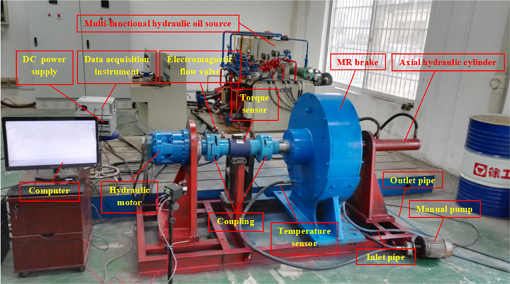
Figure 6. Temperature-torque performance experimental system.
Download figure:
Standard image High-resolution imageThe MRF for this experiment was MRF-350 purchased from China Shenzhen Aisaike Lubrication Materials, Co., Ltd It was comprised of soft magnetic carbonyl iron particles (average diameter: 3 μm, density: 7.86 g cm−3; Beijing DK Nano Technology Co., Ltd), dimethyl silicone oil (viscosity: 100 cSt at 25 °C, density: 0.965 g cm−3; Shin-Etsu, Japan), sodium dodecyl benzene sulfonate, oleic acid (purity 90%), graphite, and diatomite powder. The performance was tested by the Beijing laboratory of Anton Paar Co., Ltd. The test results indicated that the MRF-350 possessed zero field viscosity of 260 mPa and saturation yield stress of 58.6 kPa. The working temperature of MRF-350 was –40 °C–150 °C.
4. Results and discussion
4.1. Relationships between excitation current and braking torque
The rotation speed was maintained at 200 r min−1, the excitation current was increased from 0 to 15 A, the relevant variation curves of the excitation current and braking torque was shown in figure 7. As can be seen in the figure that the braking torque increased with the excitation current, the braking torque can reach 1410 N · m when the excitation current reached 15 A, and at this current, the magnetic particles have not yet reached magnetic saturation. Furthermore, the braking torque exhibited an almost linear increase with the excitation current within 0–5.5 A. As the excitation current continued to increase, the increasing trend became slow. This phenomenon became more obvious when the excitation current increased from 11 to 15 A, this is due to the particles are close to magnetic saturation. The five theoretical values were slightly greater than experimental values, which had an average error of 2.4% compared with the experimental values. The reason for this phenomenon was that some nonmagnetic materials existed in the magnetic circuit and resulted in the actual magnetic field intensity of the working gap lower than our design value. In this high-torque brake, this small error could be accepted.

Figure 7. Curves of braking torque and excitation current
Download figure:
Standard image High-resolution image4.2. Relationships between braking torque and axial squeezing stress
The rotation speed was maintained at 200 r min−1 and the excitation current were maintained at 5 A, 10 A and 15 A, respectively. The axial squeezing stress was adjusted from 0 to 1.5 MPa by adjusting the electromagnetic flow valve from 0 to 20 MPa. Figure 8 showed the relationships between the braking torque and the axial squeezing stress at different excitation currents and indicated that all the braking torques at different excitation currents exhibited an almost linear increase with the squeezing stress. Moreover, the maximum braking torque was 1410 N m without squeezing stress. However, it reached 2710 N m when the axial squeezing stress reached 1.5 MPa, which was an increase of 1300 N m. This result could be explained by the fact that the space length along the direction of the magnetic particle chains decreased, and the cohesion in each magnetic particle became stronger, indicating a greater shear yield stress. The result also presented the feasibility of our design with respect to the pressure effect. As a result, the high-torque characteristics could be fully realized in our experiments. So far, the feasibility of pressure effect on MRF is verified by our experiments.
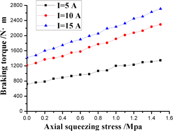
Figure 8. Curves of the braking torque and the axial squeezing stress at different excitation currents.
Download figure:
Standard image High-resolution image4.3. Effect of the temperature on the braking torque
Figure 9 presented the relationship between the obtained temperature and braking torque. The initial torque was 1800 N m, which was adjusted through the axial squeezing stress and the excitation current.

Figure 9. Curve of the temperature and the braking torque.
Download figure:
Standard image High-resolution imageFigure 9 indicated that the braking torque decreased by 210 N m, which decreased from 1800 to 1590 N m when the temperature increased from 25 °C to 150 °C. The curve exhibited a variation trend that was initially increasing then decreasing, which was inconsistent with the results of other researchers [14]. In [14], the curve initially showed a decreasing trend caused by the decrease of the dynamic viscosity of MRF. The inconformity between them was due to that the reduced dynamic viscosity of the MRF was relatively small, which could be fully compensated by the pressure effect of the MRF. Then, the variation of the dynamic viscosity could not be exhibited solely and clearly. Figure 9 showed that the braking torque exhibited an increasing trend when the temperature increased from 25 °C to 55 °C, which was because of the indirect pressure effect caused by the thermal expansion of the MRF. The thermal expansion can make the cohesion in each magnetic particle stronger, resulting in a greater shear yield stress. In addition, it should emphasize that most of the research efforts have assumed that Brownian motion is negligible [38–43] but there are also some reports where thermal motion is considered in spite of the large size of the constituents [44]. In this work the average diameter of the soft magnetic carbonyl iron particles in MR fluid was 3 μm, which may produce Brownian motion of the particles [45]. Consequently, more energy may be consumed for the magnetic particles to overcome the Brownian motion to form a chain-like structure. As a result, the structural stability of magnetic particle chains was weakened because of the Brownian motion, thereby resulting in a decrease in the braking torque when the temperature increased from 55 °C to 90 °C. Thereafter, the magnetization intensity of magnetic particles was seriously weakened, the viscosity of base fluid was decreased and the activity of additives was reduced, which caused a clearer decreasing trend of the braking torque.
4.4. Temperature variation of the MRF at different slip powers
The rotation speed of hydraulic motor was maintained at 200 r min−1 by adjusting the output power of the pump and the cooling water flow rates was kept in 3 l min−1. Meanwhile, the axial squeezing stress and the excitation current were adjusted to make the brake work at different slip powers of 5 kW, 10 kW, 20 kW and 30 kW, respectively. At 50 s, the motor supply was cut off and the DC power supply was turned off. Figure 10 showed the temperature curves in terms of time at different slip powers.
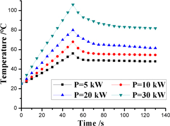
Figure 10. Curves of the temperature in terms of time at different slip powers.
Download figure:
Standard image High-resolution imageFigure 10 indicated that the temperature of the MRF exhibited an almost linear increase at different slip powers during the working processes, and the maximum temperatures achieved were 56 °C, 68 °C, 87 °C and 104 °C when the corresponding slip powers were 5 kW, 10 kW, 20 kW and 30 kW, respectively. This result led to the conclusion that the rate of temperature rise increased with an increase in the slip power. The reason for this phenomenon was that the generated heat was accumulated in the working gap, and no sufficient time was given for dissipation. In addition, the generated heat in unit time was proportional to the slip power. Thereafter, in the shutdown stage, the temperatures showed a clear decreasing trend in the beginning until it became gradually stable. This can be explained by the fact that a relatively large temperature difference existed in the working gap and components in the beginning, which contributed to a rapid heat dissipation. After this, it became more difficult for the heat transferred to the shell, this was because the thermal resistance of the cooling channel was high, thereby resulting in the decreasing trend became slow until nearly stable.
4.5. Temperature variation of the MRF at different cooling water flow rates
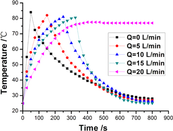
The axial squeezing stress and excitation current were adjusted to make the brake run at a slip power of 20 kW, the rotation speed of hydraulic motor was maintained at 200 r min−1. The flow control valve was adjusted to make the brake work in different cooling states, which cooling water flow rates were 0 l min−1, 5 l min−1, 10 l min−1, 15 l min−1 and 20 l min−1, respectively. The motor supply was cut off and the DC power supply was turned off when the temperature of the MRF reached 80 °C. Figure 11 showed the temperature curves in terms of time at different cooling water flow rates.
Figure 11. Curves of the temperature in terms of time at different cooling water flow rates
Download figure:
Standard image High-resolution image
Figure 11 indicated that the temperature of the MRF more rapidly increased, and heat more slowly dissipated without cooling water. Meanwhile, at the same slip power, the corresponding times for the temperature of the MRF reached 80 °C were 44, 145, 235 and 310 s when the cooling water flow rates were 0 l min−1, 5 l min−1, 10 l min−1 and 15 l min−1, respectively. This was due to the rate of temperature rise of the MRF and the cooling water flow rate being negatively correlated. Moreover, the MRF was maintained at a constant temperature of 75 °C at 400 s, when the corresponding cooling water flow rate was 20 l min−1. One conclusion that can be drawn was that an effective cooling method contributed to the functioning of high-torque MR brakes in a more stable state. In the shutdown stage, the curves in figure 11 indicated that a larger cooling water flow rate could increase the cooling rate of the MRF.
In figures 10 and 11, the cooling water flow rates and the slip powers on the effect of MRF temperature effectively verified the energy balance equation in qualitative. Figures 9–11 also showed that an effective cooling method was necessary to assist the MR brakes for heat dissipation, especially for high-torque or high-power MR brakes to control the variation in temperature.
5. Conclusions and future work
This study elaborated the detailed theoretical analysis of a disc brake, the pressure characteristics of the MRF in axial and the heat dissipation in an MR brake. A high-torque squeezing MRF brake with a water cooling method for heat dissipation was designed and a temperature-torque performance experimental system was established. The relevant experimental results indicated that the high-torque squeezing MRF brake possessed workable pressure characteristics, which contributed to the operation of our experiments in the high-torque transmission range. Furthermore, the braking torque exhibited a variation trend that was initially increasing then decreasing when the temperature increased from 25 °C to 150 °C, the magnitude of decrease was approximately 210 N m, which decreased from 1800 to 1590 N m. Meanwhile, the temperature of the MRF presented an almost linear increase at different slip powers and the rate of temperature rise increased with an increase in the slip power. A larger cooling water flow rate could increase the cooling rate of the MRF.
The effect of temperature on the transmission characteristics of a high-torque squeezing MRF brake was studied in detail. However, the control methods to maintain the braking torque at a specific value have not yet been conducted, and it is still unknown whether there are more energy-saving and effective cooling methods for heat dissipation in high-torque and high-power MR devices. These aspects should be important research topics for future studies.
Acknowledgments
This research is supported by the National Natural Science Foundation of China (No. 51475454), National Natural Science Foundation of Jiangsu Province (No. BK20151144), Scientific and Technological Research Program of Chongqing Municipal Education Commission (No. KJ1710261), Priority Academic Program Development of Jiangsu Higher Education Institutions (PAPD), Taishan Scholar (tsqn1812025) and Australia ARC DECRA (No. DE190100931).
Conflict of interests
The authors declare that there is no conflict of interests regarding the publication of this article.