

Abstract
This paper presents a monolithic novel polydimethylsiloxane-based dual-channel bellows-structured pneumatic actuator, fabricated through a sacrificial molding technique. A finite element analysis was performed to find the optimal structure and analyze the bending performance of the square-bellows actuator. The actuator was designed with an overall cross-sectional area of 5 × 5 mm2, while its structural parameters were characterized in terms of 8, 12, 16 and 20 number of bellows. The actuator models were fabricated using acrylonitrile butadiene styrene-based sacrificial molds to form the channel and bellows structures. The experimental validation has revealed that the actuator having highest number of bellows with a size of 5 × 5 × 68.4 mm3 attained a smooth bi-directional bending motion, with maximum angles of −65° and 75°, and force of 0.166 and 0.221 N under left and right channel actuation, respectively, at 100 kPa pressure. Hence, the state-of-the-art dual-channel square-bellows actuator was able to achieve an optimal bi-directional bending with slight variations to change in temperature, which would push the boundaries of soft robotics toward the development of safer and more flexible robotic surgical tools.
Export citation and abstract BibTeX RIS
1. Introduction
The technological advancement in the field of robotics has drastically increased the development of robotic assistive tools for minimally invasive surgery (MIS). Starting from 1987, MIS has proven to be advantageous over conventional open surgery [1], by offering a reduction in postoperative pain and risk of wound infection [2]. MIS utilizes an endoscope to access the interior organs or tissue of the patient's body via small incisions (5–15 mm). To allow a smooth entrance and progression to an endoscope inside the patient's body, preliminary insertion of a small catheter is essential without sacrificing its ability to maneuver. Therefore, considerable resources have been invested in upgrading the conventional endoscopes [3] and developing new flexible endoscopes and active catheters. Some of the leading commercially available flexible video colonoscopes, such as Olympus EXERA Ill CF-Q190L and PENTAX Medical RetroView™ EC34-i10T, offer an ergonomically designed grip to provide excellent scope maneuverability and handling. However, having a larger diameter, these endoscopes need further improvement.
Many researchers have utilized micro-electromechanical systems (MEMS) to develop small-scale tools and devices to facilitate robotic surgery. Indeed, there are various MEMS actuators that offer bio-compatibility and strong manipulation force at a miniature size. Some of the reputed thermal actuators from MEMS include shape-memory alloys (SMAs), and shape-memory polymers (SMPs). For example; SMAs have been proved by their extensive use in medical implantable devices, surgical tools and catheters [4, 5]. NiTi, or nitinol, a type of biocompatible SMA, operates on the phenomena of 'shape-memory effect', which occurs when the SMA is deformed at martensitic phase and heated up to austenitic phase to regain its 'original' shape [6–9]. Some of the SMA-based surgical devices include a 1.2 mm diameter catheter [10] and a worm-shaped endoscope developed to maneuver inside the body [11].
Besides SMAs, SMPs are smart materials which can also recover a predetermined permanent shape from a temporarily fixed shape upon the application of external stimuli such as heat, pH, light, electric and/or magnetic fields, etc [12]. SMPs have various advantages over SMAs, including a high recoverable strain, easy processability, low cost, and low density [13, 14], which allows their applications to be extended to biomedical devices [15, 16]. Despite various advantages offered by SMA and SMP-based thermal actuators, the heat dissipation issues related to these actuators make them unsafe for MIS. In addition, the slow actuation characteristic limits their applications in surgical procedures. In order to address the issues associated with thermal actuators, smart materials based electroactive polymer artificial muscle (EPAM) which is also known as electroactive polymer has been explored. This actuator consists of two compliant electrodes which are sandwiched on a flexible center layer [17]. The EPAM posses various advantages such as fast response, high force and large deflection against applied electric field. Considering these characteristics, many researchers have utilized EPAM in developing surgical robotic devices and snake-like endoscopes [18, 19]. However, the high operating voltage required by the EPAM, makes it undesirable in surgical application. Since surgical robotic systems are considered as the future of MIS, the demand for safe, flexible and biocompatible robotic assistive tools leads the researchers to explore soft actuators.
Soft actuators made from highly compliant elastomer material offer bio-compatibility, high flexibility, and safety, which makes them promising candidates for endoscopic application [20, 21]. The structure of soft actuators consists of internal channel(s) for pneumatic or hydraulic supply, while they are often reinforced with fiber to improve actuation [22], such as McKibben artificial muscle [23]. The input pressure to the actuator's channels causes elastic deformations in its structure [24], which results in actuation. However, soft actuators driven by hydraulic supply result in a heavier structure with limited degrees of freedom and bending motion compared to a soft actuator driven by pneumatic supply. Moreover, a pneumatic soft actuator with two channels can attain bi-directional bending [25, 26], while an actuator with three channels can support bending up to six directions [27]. Using their characteristics, a pneumatic soft-actuator-based colonoscope [28, 29] and a flexible bronchoscope [30] were developed, which can perform bending and twisting motions, respectively. Soft actuators have found enormous applications in medical robotics.
Soft actuators which are commonly made of liquid elastomers, such as polydimethylsiloxane (PDMS) require channel(s) for actuation. This increases the complexity of their fabrication process. The most popular technique is molding an elastomeric material and gluing it to a stiffer material, as reported for the fabrication of PneuNets, which comprises of a paper layer, embedded between two elastomer layers, and bonded to the main body [31, 32]. There are many other works reported to use molding and bonding fabrication technique for pneumatic actuator fabrication [24, 33–36]. Similar fabrication method has also been adopted for the fabrication of microfluidic device [37]. However, soft actuators with complex and sophisticated designs are difficult to be fabricated through molding process. This raised the demand for new fabrication tools, such as; 3D printing, which facilitates the formation of high resolution molds [38–41], and formation of complex 3D structures [42, 43]. The 3D printing technology could further facilitate the development of soft actuators by eliminating the need for bonding process. Most of the aforemention pneumatic actuators consist of single channel for unidirectional bending, while their structures composed of stiffer material parts, bonded to restrict swelling effect and support bending, which may result in leakage during operation.
This study presents a novel monolithic PDMS-based dual-channel bellows-structured pneumatic actuator, fabricated through a sacrificial molding technique that minimizes the risk of leakage by eliminating the bonding process. The actuator developed through this technique also offers self-supportive bi-directional bending and simple fabrication steps. In addition, the developed method also enables the fabrication of miniturized size actuator. The structural parameters of the actuator are characterized in terms of number of bellows to develop four models. Finite element analysis (FEA) is performed to analyze the bending performance of each model. The actuator models are fabricated, while the bending performance is validated, and the bending force is determined experimentally at room temperature. Moreover, the bending performance of the characterized actuator models is also validated for thermal susceptibility.
2. Design configurations
The design of the proposed PDMS-based dual-channel pneumatic actuator consists of square-shaped bellows, embedded in each channel (see figure 1(a)), to support the actuator in achieving bi-directional bending motion [44]. Applying a pneumatic pressure to the left channel of the bellows actuator generates contraction and expansion in its structure, which results in a bending motion towards the right direction (see figure 1(b)), and vice versa. To analyze the bending performance of the square-bellows actuator, its structural parameters (see figure 1(c)), were characterized by keeping the actuator wall thickness,  actuator width,
  actuator height,
  bellows width,
  and bellows spacing,
  constant, while the number of bellows,
  and the actuator length,
  were varied to develop four models. The structural parameters of the developed models are tabulated in table 1.
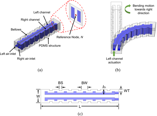
Figure 1. Dual-channel square-bellows pneumatic actuator: (a) structural design, (b) working principle, (c) cross-sectional view: actuator width,  actuator length,
  bellows width,
  bellows spacing,
  wall thickness,
  bellows height,
Download figure:
Standard image High-resolution imageTable 1. Structural parameters of four developed models of dual-channel square-bellows actuator.
| Structural parameters (mm) | ||||||
|---|---|---|---|---|---|---|
| Model | B | BS | BW | WT | W × H | L |
| 1 | 8 | 1 | 2.4 | 0.7 | 5 × 5 | 27.6 |
| 2 | 12 | 1 | 2.4 | 0.7 | 5 × 5 | 41.2 |
| 3 | 16 | 1 | 2.4 | 0.7 | 5 × 5 | 54.8 |
| 4 | 20 | 1 | 2.4 | 0.7 | 5 × 5 | 68.4 |
2.1. Material properties and geometrical analysis
Following Rivlin, the hyper-elastic PDMS material selected for developing the dual-channel square-bellows actuator assumed to have rubber-like, isotropic, and isothermal elastic properties, which may be described in terms of a strain energy function,  For incompressible materials, Rivlin has pointed towards the reduced form of the strain energy function equation in terms of power series as follows [45]:

where  is strain energy,
  is a material constant, and
  and
and  are strain invariants, while
  represents the model order. The
  and
and  for a hyper-elastic material under tension-compression can be presented as follows:


For an incompressible material such as PDMS under tension-compression, the relation between engineering stress,  and stretch,
  can be expressed as follows:

Based on the tension-compression of a hyper-elastic incompressible material, the nth-order Yeoh model expression can be retrieved by combining equations (1) to (4):

The effects of the structural characterization of the bellows actuator design on its output bending performance and force exerted can be modeled through the hyper-elastic Yeoh model, under tension-compression. Assuming the incompressibility of PDMS material across the width of the actuator, the expression for the Yeoh model for each individual bellows becomes of the form presented in equation (6) [46]:

where  is the principal stretch along the bellows, and
  is the curve angle of the inflated bellows. From figure 1(c), assuming the bellows wall thickness,
  to be much smaller than the bellows height,
  (i.e.
(i.e.  ),
),  can be neglected. Hence,
  becomes a function of
  and the inflation distance,
  as expressed in equation (7):

The stress,  is also a function of
  and
and  Hence, differentiating equation (6) w.r.t. to
  results in stress, as expressed in equation (8):

Considering that each bellows is rigidly rotating around the interconnection point, the relationship between the resulting increase in the exerted force,  perpendicular to the bellows in response to the increase in supplied air pressure,
  can be expressed by equation (9):


where  is the width-justified lever of
 determines how an increase in air pressure affects the exerted force at a certain configuration as a function of
  To achieve a larger value of
  a smaller value of
  is desirable. Thus, to reach the same curvature angle for a given actuator length, less expansion (smaller
  ) is required with a larger
  Thus, from equation (11), as
  is directly proportional to
  and inversely proportional to
  keeping a larger
  or a smaller
  would significantly increase
  The expressions presented in equations (7) and (10) can be used to model the output bending angle and the force exerted by the bellows actuator, respectively. Hence, having a larger
  thinner
  and higher
  would eventually improve the output performance of the bellows actuator. However, this study covers the structural characterization of the square-bellows actuator in terms of
  only, to develop four models and experimentally validate the bending performance and exerted force by the bellows actuator.
3. Simulation setup and analysis
FEA was performed to simulate the bending behavior of each bellows actuator model using MARC® software, which is recommended for the characterization and analysis of nonlinear behavior of material structures. Using the graphical user interface of MARC® software, the nodes were connected to form elements, which were further combined to form the overall structure of the actuator. Next, the material property for PDMS was defined by inserting the values of  = 0.57 MPa and μ = 0.5.
For assigning the boundary conditions, both actuator channels were marked with a maximum face-load (input pressure) of 100 kPa, supplied in 1000 increments (load-case) during simulation. To linearly apply the input pressure during simulation, a contact table (linear curve) was plotted in MARC® software and assigned to each actuator channel. To hold the actuator, a fixed displacement along the 
 and
and  axes was applied at one end of the actuator. A reference node,
  was marked at the center of the bending end of the actuator (see figure 1(a)), to track the displacement covered by the actuator during the simulation, which was further utilized for calculating the bending angle,
  attained by the dual-channel square-bellows actuator [47]. By keeping all the above settings of MARC® constant, four actuator models were simulated, while their bending displacement was traced and analyzed to calculate
3.1. Bending angle (θ) calculations
As highlighted in the previous section for tracking the bending displacement, the node  was selected at the center of the bending side of the actuator. For
  calculation, a right-angled triangle,
  was marked on the resulting simulation profile of the actuator (see figure 2). Considering
  as one corner of the right-angled triangle, the side
  of the right-angled triangle represents the displacement,
  covered by the actuator along the
  -axis. While performing the bending motion with respect to
  the actuator was also displaced along the
  -axis, which resulted in a reduction in length,
  from its total length,
  (see figure 2). The side
  of the right-angled triangle represents the change in length, or the new length,
  determined from the relation:
  Thus, by applying the trigonometric function expressed in equation (12), the
  achieved by each actuator model was calculated against the respective input pressure. The simulation results for the bending angle attained by each actuator model will be presented later in detail in section 5.1.

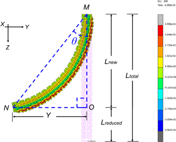
Figure 2. Simulation results of bellows actuator (Model 4) at 60 kPa pressure.
Download figure:
Standard image High-resolution image4. Fabrication of dual-channel square-bellows actuator
The development of the proposed dual-channel square-bellows pneumatic actuator design, involves the preliminary fabrication of two sacrificial molds. In this respect, different soluble materials were tested, and, finally, acetone soluble ABS material was selected for the process.
First, the inner and outer sacrificial molds were designed using SolidWorks® software (see figure 3(a)) and then 3D printed using ABS material. The actual 3D printed molds are shown in figure 4(a). Both sacrificial molds were aligned, matted and glued (see figure 3(b)). Next, the PDMS (Sylgard® 184 A/B) from Dow Corning Corporation, MI, USA, was mixed in ratio 10:1 and poured onto the matted molds (see figure 3(c)). To remove the air bubbles from uncured PDMS, the sacrificial molds were placed in a vacuum desiccator for 40 min (see figure 3(d)). Then, the sacrificial molds with PDMS were cured using a hot plate at a temperature of 90 °C, i.e. below the melting temperature of ABS (220 °C) for 40 min.
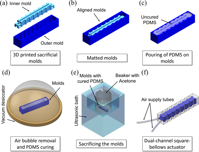
Figure 3. Fabrication process of pneumatic bellows actuator using sacrificial molding.
Download figure:
Standard image High-resolution image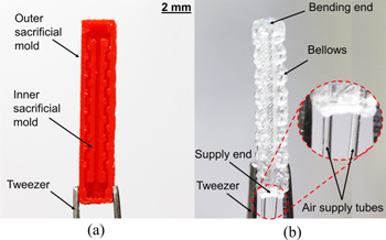
Figure 4. Fabrication results of dual-channel square-bellows actuator (Model 1): (a) sacrificial molds. (b) Extracted actuator.
Download figure:
Standard image High-resolution imageOnce the PDMS was cured, the sacrificial molds were dissolved in acetone using an ultrasonic bath at 45 °C for 1 h (see figure 3(e)). Once both ABS-based inner and outer molds were completely swallowed in acetone, the actuator was ready for extraction. The developed actuator was rinsed with isopropanol, deionized water and dried with pressurized nitrogen. The actuator was sealed from one end, while a silicone tube was inserted to each channel from the other end, to connect the actuator with the pneumatic supply (see figure 3(f)). The final fabricated actuator is shown in figure 4(b). The developed fabrication technique was followed to fabricate all four models of square-bellows actuator (Models 1–4).
5. Results and discussion
In this section, the discussion focuses on the simulation and experimental results achieved by the bellows actuator (Models 1–4). The bending performance validation of each actuator model is elaborated at room temperature and thermally characterized, while the bending force exerted by each actuator model is also discussed hereafter.
5.1. Simulation results
As discussed in the previous section, MARC® software was utilized to characterize the bellows actuator by keeping the values of  = 5 mm,
  = 5 mm and
  = 0.7 mm constant, while varying the
  from 8, 12, 16 up to 20, which eventually increased the length of each model from 27.6 mm, 41.2 mm, 54.8 mm to 68.4 mm respectively. For FEA of each model, the MARC® software settings such as material property, boundary conditions, face load and load-case were kept constant, while maximum input pressure up to 100 kPa was linearly applied to each channel of the actuator. However, the simulation results of the square-bellows actuator converged up to a pressure of 65 kPa, which revealed that each model resulted in uniform bi-directional displacement and bending motion along –yz-axes. Moreover, the increase in number of bellows, B, of the actuator to form Models 1–4, imposes a proportional increase in bending displacement (see figures 5(a) and (b)) and bending angles (see figure 5(c)) attained by each respective model, determined using equation (12) mentioned earlier in section 3.1. The maximum bi-directional bending angles achieved by each actuator (Models 1–4) were ±17°, ±26°, ±35° and ±42° at input pressure of 65 kPa, respectively. Hence, the simulation results revealed that the square-bellows actuator showed a symmetrical behavior in terms of displacement and bending angle with equal and opposite magnitude, which makes it worthy for experimental validation.

Figure 5. Simulation results of dual-channel square-bellows actuator; (a) displacement in  direction, (b) displacement in
  direction, (c) bending angle as a function of input pressure.
Download figure:
Standard image High-resolution image5.2. Experimental setup and results
As mentioned in the previous sections, four actuators models were fabricated for bending angle validation and to determine the exerted force at room temperature. As previously mentioned, one end of each actuator model was sealed, while a silicone tube was inserted in each channel of the actuator model from the other end, to connect the actuator with the pneumatic supply as illustrated in figure 6(a). A control valve and a pressure regulator were also connected within the supply line, to supply a controlled and regulated amount of air to the actuator. To evaluate the bending performance and validate the bending angle attained by each actuator model, the setup illustration (see figure 6(a)) was followed to install the actual experimental setup (see figure 6(b)). During the experiment, a control amount of pneumatic supply was provided to each actuator model via the pressure regulator. Thus, by manually adjusting the regulator, the applied pressure to each actuator model was raised from 0 to 100 kPa with increment of 10 kPa, while the respective bending motion was recorded. Due to these discrete measurements, the response time of the bellows actuator was unable to be measured. Meanwhile, referring to the typical pneumatic actuators in this category, the expected actuation time is ∼1 s [34–36].

Figure 6. Experimental setup: (a) setup illustration, (b) actual setup.
Download figure:
Standard image High-resolution imageThe experimental results for the bending angle attained by each actuator model were recorded at room temperature (T = 25 °C). Experimental results revealed that all four models attained a smooth bi-directional bending motion (see figure 7). The increase in the number of bellows of the actuator (Models 1–4) from 8, 12, 16 up to 20 proportionally increased the bending angle of each respective model. The experimental results for maximum bending angle achieved by each actuator model against maximum input pressure of 100 kPa is tabulated in table 2. For the validation of bending angles attained by each actuator model, the experimental results (see figure 7), were further compared with simulation results, converging at 65 kPa pressure (see figure 5(c)), also tabulated in table 2. Among all actuator models, the model with highest number of bellows (Model 4) achieved the highest bi-directional bending angles of −65° and 75° under left and right channel actuation, respectively.

Figure 7. Experimental results for bending angle attained by actuator Models 1–4 at room temperature (T = 25 °C).
Download figure:
Standard image High-resolution imageTable 2. Simulation and experimental results for bending angle achieved by square-bellows actuator (Models 1–4) at T = 25 °C.
| Bending angle (θ) | ||||||||
|---|---|---|---|---|---|---|---|---|
| Results | Left channel actuation | Right channel actuation | ||||||
| Model 1 | Model 2 | Model 3 | Model 4 | Model 1 | Model 2 | Model 3 | Model 4 | |
| Simulation results at 65 kPa | −17° | −26° | −35° | −42° | 17° | 26° | 35° | 42° |
| Experiment results at 65 kPa | −16° | −12° | −17.5° | −25° | 18° | 29° | 31° | 39° |
| Experiment results at 100 kPa | −25° | −25° | −35° | −65° | 35° | 60° | 62.5° | 75° |
From the evaluation of each actuator model, it can be validated that for right channel actuation, the experimental results for the bending angle almost followed the simulation results, while for left channel actuation, the experimental results for the bending angle have shown some discrepancies compared to the simulation results. This might be due to the non-uniformity in the fabrication process, either due to the use of a low-resolution 3D printer in fabrication of sacrificial molds or human error occurring due to manual alignment, matting and gluing of sacrificial molds, causing uneven channel formation for each actuator model. After validating the dual-channel square-bellows actuator at room temperature, all four actuator models were evaluated for thermal susceptibility and stability. For thermal characterization, the previous experimental setup (see figure 6), was upgraded. First, the actuator models (Models 1–4) were enclosed in a vacuum desiccator (PELCO® Mini Hot Vac, Tedpella, USA), having glass top and aluminum base-plate. PMMA sheets were placed as thermal isolation between the desiccator base-plate and the actuator. To measure the actuator temperature inside the vacuum desiccator, a K-type thermocouple was attached to the actuator. Finally, the actuator enclosed inside the vacuum desiccator was placed on a temperature source (hotplate). The experimental setup was ready to validate the bending performance of each actuator model under thermal susceptibility. Once the hotplate was turned on, by controlling the hotplate temperature, the cavity or actuator temperature was varied from 30 °C, 35 °C, 40 °C, 45 °C to 50 °C, measured using the K-type thermocouple. At each cavity temperature, the square-bellows actuator models were actuated with a maximum pressure up to 100 kPa, while the resulting bending angles attained by each model (Models 1–4) were recorded respectively (see figures 8(a)–(d)).

Figure 8. Bending angle results attained by actuator under thermal characterization at T = 25 °C–50 °C; (a) Model 1, (b) Model 2, (c) Model 3, and (d) Model 4.
Download figure:
Standard image High-resolution imageThe bending performance and susceptibility of the bellows actuator were validated under thermal characterization. Thus, by comparing the bending angle results achieved by each actuator model (see figure 8) with the bending angles achieved at room temperature (see figure 7), it can be validated that every 5 °C rise in the actuator temperature from 25 °C–50 °C causes very minor effects on the bending angle results attained by each model. The developed actuator (Models 1–4) performed well under thermal characterization, while the effects of temperature on the bending performance of the actuator were very minimal. Hence, all models of the PDMS-based dual-channel square-bellows actuator were found to have slight variations in bending angle with change in temperature. However, among all actuator models, Model 4 achieved the highest bending angle under thermal characterization, as tabulated in table 3.
Table 3. Maximum bending angle achieved by the square-bellows actuator (Models 1–4) under thermal characterization at maximum applied pressure of 100 kPa.
| Bending angle (θ) | ||||||||
|---|---|---|---|---|---|---|---|---|
| Actuator's temperature (°C) | Left channel actuation | Right channel actuation | ||||||
| Model 1 | Model 2 | Model 3 | Model 4 | Model 1 | Model 2 | Model 3 | Model 4 | |
| 30 | −30° | −40° | −40° | −62.5° | 30° | 55° | 60° | 72.5° |
| 35 | −22.5° | −27.5° | −37.5° | −65° | 22.5° | 47.5° | 55° | 67.5° |
| 40 | −25° | −25° | −37.5° | −67.5° | 27.5° | 52.5° | 57.5° | 72.5° |
| 45 | −25° | −25° | −37.5° | −60° | 27.5° | 52.5° | 55° | 70° |
| 50 | −20° | −27.5° | −37.5° | −57.5° | 25° | 50° | 52.5° | 67.5° |
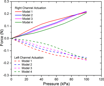
Besides bending performance, the bending force exerted by each actuator model was also determined in this study. A digital force gauge (ZTA-5N, IMADA Co., Ltd Kanowari, Japan) was used to measure the actuation force at bending end of the actuator. Each actuator model was mounted on the built-in displacement bed attached to the digital force gauge, in a way that the actuator's tip at the bending end in contact with the gauge sensor. The force gauge was connected to a laptop using a USB cable. Force Recorder Professional® software was used to record the output bending force attained by each actuator model (Models 1–4) against linearly applied input pressure up to 100 kPa. Force measurement results revealed that all the actuator models attained bi-directional bending force with approximately equal magnitude (see figure 9). However, among all four actuator models, Model 3 resulted in maximum bi-directional bending force of −0.178 and 0.221 N under left and right channel actuation, respectively, as tabulated in table 4.
Figure 9. Force resulting from dual-channel square-bellows actuator Models 1–4 at room temperature (T = 25 °C).
Download figure:
Standard image High-resolution image
Table 4. Output force attained by square-bellows actuator (Models 1–4) at maximum applied pressure of 100 kPa.
| Maximum force (N) | ||
|---|---|---|
| Model | Left channel actuation | Right channel actuation |
| 1 | −0.168 | 0.212 |
| 2 | −0.155 | 0.216 |
| 3 | −0.178 | 0.221 |
| 4 | −0.166 | 0.207 |
6. Concluding remarks
The PDMS-based dual-channel square-bellows pneumatic actuator developed through a novel sacrificial molding technique helped to understand the effects of the volume of an actuator on its bending motion. The actuator was designed with a constant cross-sectional area of 5 × 5 mm2, while its structural parameters were characterized by varying the number of bellows,  from 8, 12, 16 up to 20, to develop four models (Models 1–4). Eventually, the length of each model was also increased from 27.6, 41.2, 54.8 up to 68.4 mm respectively. The FEA results converged up to 65 kPa, revealing that each actuator model achieved bi-directional bending motion with maximum angle of ±17°, ±26°, ±35° and ±42° respectively. At room temperature and up to maximum input pressure of 100 kPa, the bellows actuators (Models 1–4) attained bending angles of −25°, −25°, −35°, −65° and 35°, 60°, 62.5°, 75° with bending force of around −0.166 N and 0.207 N under left and right channel actuation, respectively. However, the experimental validation for each actuator model revealed visible percentage deviations of 5.9%, 11.5%, 11.4%, 7.1% and 5.9%, 53.8%, 50%, 40.5% under right and left channel actuation, respectively. This might be a result of uneven channel formation for each actuator model, due to the low-resolution 3D printer used for fabrication and the manual alignment, matting and gluing of sacrificial molds. The thermal characterization and validation of each actuator model revealed that every 5 °C rise in actuator temperature from 25 °C–50 °C resulted in very minimal effects on the bending performance of the developed actuator. Hence, the state-of-the-art dual-channel square-bellows actuator developed under this study has offered a simple fabrication method for small-scaled soft actuator designs having multiple channels and complex structures. The thermal insusceptibility achieved by the actuator would push the boundaries of soft robotics towards the development of safer, more flexible, and more thermally stable surgical robots, especially for MIS application. The future direction of this research will mainly focus on further miniaturization of bellows-structured soft actuator using the standard photo-lithography technique and its characterization in terms of response time, sensitivity and resolution.
Acknowledgments
This work was supported by Universiti Teknologi Malaysia under Research University Grant (GUP 17H61) and Collaborative Research Grant (CRG 05G35). Tariq Rehman acknowledges the financial support from NED University of Engineering and Technology, Pakistan, under PhD Scholarship M3.