

Abstract
Nitinol (NiTi) shape memory alloy (SMA) heat engine is a very promising candidate application of SMA since its invention, but yet to be put as commercial due to its low efficiency and performance. In this paper, a review of different types of NiTi SMA heat engine is presented. The review is done based on the following headings: conceptual design, constitutive driving model, the performance of the engine, and engine limitations. Factors like temperature, cooling rate, size of NiTi SMA element, and the stretch ratio of NiTi SMA spring were identified as determinants of final output power and efficiency of SMA heat engines. It is found that a crankshaft NiTi SMA heat engine produced the highest power output value of 4 watt, an unsynchronized pulley NiTi SMA heat engine with 11.3% of engine efficiency has the highest engine performance so far recorded. Some engine's drawbacks like an improper driving model, drag loss, backsliding were identified as the major problem affecting the engine performance, and which, if solved, will increase the overall performance and efficiency for future development toward its commercialization.
Export citation and abstract BibTeX RIS
1. Introduction
For the wellbeing of human beings, energy demand is rapidly increasing every day. For this reason, many sources of energy are explored to achieve this goal. These energy sources range from the use of firewood, coal, petroleum, solar, nuclear, to mention just a few [1–5]. However, some of these energy sources, like fossil fuel [6], are hazardous due to carbon footprint [7] and are nonrenewable. Hence, an alternative, safer, and renewable sources [8, 9], will be of great importance. These renewable sources such as wind energy [10, 11], solar energy [12, 13], hydropower [14, 15], biomass [16–18] and the like are more peaceful in nature. Our ecosystem consists of different sources of waste heat of low energy density. Recovering this waste energy will add to the availability of energy sources for domestic [19] and industrial use. More than 60% of this energy wasted is at less than 373 K [20]. Solar radiation alone is directly converted into this low-grade heat with energy flux of about 8 × 10¹⁶ watt, and 70% of this flux is heating ocean water, which can as well be converted to useful energy [21]. One alternative means of using this energy is by the use of Nitinol (NiTi) shape memory alloy (SMA) heat engine to harvest such waste heat energy. This will not only provide an additional source of energy but also helps in reducing greenhouse gasses caused by fossil fuels [22], for global environmental protection [23, 24]. In thermodynamics, a heat engine is defined as an engine that takes in a quantity of heat or thermal energy and converts it to mechanical energy [25]. The SMA heat engine is a kind of engine that to induce austenite–martensite transformation at the grain level by absorbing heat energy, therefore, to induce a dramatic change of the structure shape and to cause significant working actuation. For the sake of continuation, most of the SMA heat engine output the mechanical energy by rotating a given load.
Nitinol is a nickel-titanium SMA metal with unique properties. This alloy exhibits pseudoelasticity (superelasticity) and shape memory properties. NiTi SMAs heat engine is a kind of engine that is designed to convert thermal energy to useful mechanical energy [26], through the use of shape memory effect (SME) of NiTi SMAs. It has been under trial as one of the applications of SMA since its invention. Its commercial application is yet not to be done due to low efficiency and performance of energy conversion. Since the 1970s, many NiTi SMA engines have been proposed because of their environmental friend behavior to turn low-grade energy into the mechanical form [27]. These engines include offset crank type, coil-turbine, flywheel type, bias spring type, and belt type engines [28]. Many prototype NiTi SMA heat engines showed some capability of generating some mechanical output power, yet producing high power by such an engine is shown infeasible [26].
Hence, the discussion about waste heat energy harvesting is essential at this time of energy crises and the search for other alternatives. Provided that the performance of the NiTi SMA heat engine can be improved, it will provide a promising candidate solution to cope with this energy problem. For example, as Ocean Thermal Energy Harvester for electricity generation. In this paper, these types of heat engines are carefully studied to get the best out of them, their designs of energy conversion mechanisms are evaluated, their limitation and weak side are identified, and their possible future improvements are addressed.
1.1. Phase transformation in SMA
SMA is a kind of material that can be made to memorize different shapes [29–31]. Moreover, when deformed, it can regain its original shape [32, 33], as the temperature is increased, thus converting thermal energy to mechanical type [34–36]. This unique property of the plastic alike deformation and subsequent full recovery is referred to as the SMEs [37–39]. The history of this noble alloy material started in 1963, where William Buehler and his coworkers discovered its behaviors of shape recovery capability [40]. Following this, the NINOL was given to the material in which NI standing for nickel and NOL attributing it to the Naval Ordinance Laboratory, where the behavior was first discovered [41]. The material produced a strange loud sound in a cold stage, which is different from that at the hot stage [38]. Over a decade, the material had drawn the researcher's attention for different engineering applications [42, 43]. After rigorous investigation, it was concluded that the material has a unique property [44] that made it different from other alloy materials and then named it NITINOL associating it to the laboratory. This alloy can recover energy up to 106J m−3, and the transformation temperature depends on Ni-content with an upper limit of 363 K [45].
NiTi SMA has two different crystal structures with different properties [46]. Austenite (A) is stable when SMA is at high temperature and Martensite (M) at low temperatures. At Nitinol, austenite has a cubic shape [47], while martensite is tetragonal, austenite–martensite diffusionless phase transformation could be performed via sheer lattice distortion when the temperature is changed [48]. The phase transformation can produce multiple martensite variants, which are martensitic crystals with different orientation directions. Martensite variants can be twinned (Mt) and de-twinned (Md). The reversible transformation from austenite to martensite [46] and vice versa results in SMA behavior [49], and it is known that the martensitic transformation can be caused by both temperature and stress [50], which are referred to as SME and pseudoelasticity, respectively [51–53]. The essential actuating ability of the NiTi SMA heat engine is a consequence of the pseudoelastic and SME of SMA material.
1.2. Shape memory effect
SME is a phenomenon that, when SMA with a given configuration at high temperature is cooled down to low temperature, it could be deformed easily to a new configuration like plastic material by external stress, and keep the deformed configuration when the load is removed. When it is heated up to high temperature again, it regains back its original configuration [54–57]. The mechanism behind this phenomenon is shown in detail in figure 1. From point A, SMA cools through (Af−As) to point B and forms twinned martensite. It is then loaded to point C as de-twinned martensite through the plateau region. Then unloaded elastically from C to D, as the material retains the de-twinned martensite [58]. Heating in the absence of stress initiates reverse transformation when the temperature reaches As at E and completed at Af at point F. Without plastic stain during de-twinning, the original shape of the material is regained at point A.

Figure 1. The thermo-mechanical stress–stain shape memory effect [55].
Download figure:
Standard image High-resolution imageThe process starts at sufficiently high temperature when austenite is stable, and twined martensite would be formed at low temperature, then de-twined martensite will be induced upon an applied load. Finally, the crystal structure returns to the austenite state when the temperature is high gain [59]. This process is referred to as a one-way shape memory effect. When SMA is trained by cyclic thermal and mechanical loading along a specific loading path, it will exhibit a repeatable shape changes upon thermal loadings. This is called a two-way shape memory effect [42, 60]. This repeated loading causes gradual microstructural changes, which gradually lead to degradation of SMA behavior, causing low cycle fatigue [61–63].
1.3. Pseudoelasticity or super elasticity
Pseudoelasticity is a phenomenon exhibited by SMA materials [64–66]. It is a consequence of the stress-induced transformation which generates strain when an SMA material is loaded [67] and gets strain recovery when unloaded at a constant temperature above Af [54, 58, 68]. Figure 2 shows the pseudoelasticity of SMA material.
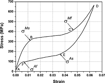
Figure 2. SMA pseudoelastic loading cycle [55].
Download figure:
Standard image High-resolution imageThe main objective of this review paper is the considerations of the NiTi SMA heat engine constitute driving model, conceptual design, and engine performance, as to identify the problems associated so that possible solutions may be proposed for its future commercialization.
2. Conceptual design
NiTi SMA heat engine may be categorized based on the principle of operation into four kinds: pulley based engines, field engines, crank engines, reciprocating engines, and miscellaneous engines [69].
2.1. Pulley engines
This category can be divided into synchronized and unsynchronized pulley engines.
2.1.1. Synchronized pulley engines.
Synchronized pulley engine is designed to have a constrained relationship whereby the pulleys rotate in a fixed relationship so that the shaft turns at the same speed or in a related orientation. A connecting timing belt, chain, gear, or taut wire rotates the wheels in direction to ease the tension. This design is among the first early invented NiTi SMA heat engine, and is designed by A.D. Johnson's in 1976, and is among the most popular concepts [35, 70]. In this design, the engine has two or more pulleys, with the first two pulleys synchronized by a timing belt. Figure 3 shows a different arrangement of this engine. This type of engine has an advantage of large SMA element being exposed to both heating and cooling media. But more materials are needed for this type of engine due to synchronization. Meanwhile, this synchronization takes up some of the power produced, thereby reducing engine efficiency.
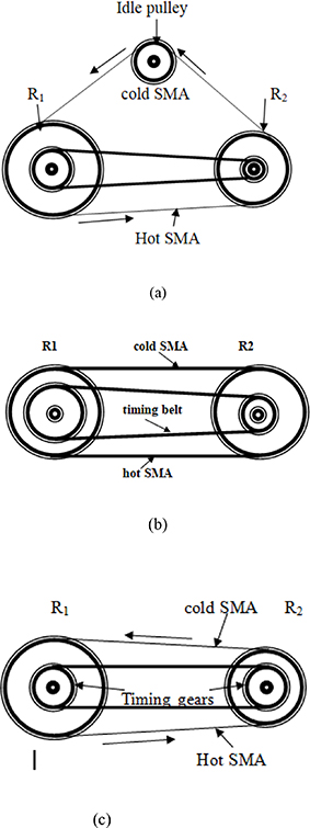
Figure 3. (a) Synchronized pulley engine with different pulley diameters and different timing gear diameter [71]; (b) Synchronized pulley engine with same pulley diameters but different timing gear diameter [72]; (c) Synchronized pulley engine with different pulley diameter but same timing gear diameter [26].
Download figure:
Standard image High-resolution imageNiTi SMA heat engine by John J Pachter (1979) is also among the ancient NiTi SMA heat engines [73], which is similar to Mr Johnson's model. The only difference is that it has four pulleys, with every two pulleys of different diameters connected by an SMA belt, which could be heated on alternative sides. The system has two shafts that connect the two pulleys each, and this made it possible to rotate in the same direction.
The working medium is another choice for the NiTi SMA heat engine, depending on the intended use. Apart from a fluid medium like hot water or air, light radiation is also used to drive a NiTi SMA heat engine. This medium has many advantages over the fluid medium. These advantages can be like the absence of drag through the working medium, easy changing of direction of rotation, less material use, high concentration of heat source, to mention a few. Hayashida et al developed a prototype for a space thermo-turbine heat engine based on Johnson's model and is tested by simulating the radiation and space environment in a space vacuum chamber [74]. The engine has two pulleys with timing gears and a timing belt for synchronizing and other two idle pulleys. The engine is designed to use solar radiation in real practice. When a NiTi SMA belt passes through a solar concentrator, it will be heated and start to contract, and then when it passes through the cooling reflector, it will be cooled and extended, thus rotating a motor/generator for electricity using the gear drive. The generator acts as a motor to start the engine before it begins to generate electricity.
Hot and cold air is also used as a working medium. A three pulleys SMA heat engine is developed with the working element of NiTi SMA spring [26, 37, 72]. The engine has two active pulleys of the same diameter and another one idle pulley at the top. NiTi SMA spring has equal wrap angles. An in-extensional timing chain is used on the sprocket of different diameters. Hot air and cold air is used for heating and cooling. Here the NiTi SMA surface area is increased by the third pulley, but there is an increase in friction loss on the third idle pulley, as shown in figure 4. Forming a joint into a continuous loop in this type of engine is one of the challenges for continuous operation.

Figure 4. Synchronized pulley engine with two active pulleys and one idle [26].
Download figure:
Standard image High-resolution imageIn another development, a four pulleys NiTi SMA heat engine (Johnson's model) is used by Martin et al to build a power plant for the generation of electricity [75]. The plant uses primary and secondary fluids with a different temperature gradient. A collector is in-cooperated to enhance the temperature difference between the fluids. The plant is buoyant in a water body, which is to use the natural occurrence temperature difference between air and water. Also, a two pulleys heat engine is developed and used for improving the efficiency and power output of the engine [71]. This engine has two unequal pulleys and timing gear diameters and operates between hot water and cold air also, as shown in figure 5. Like others of its type, the engine has a joining problem also.

Figure 5. Schematic diagram of the martensitic rotor engine [71].
Download figure:
Standard image High-resolution imageIn some engines, instead of the timing belt, series of gears are used to synchronize the two pulleys. Aono et al designed a gear type synchronized NiTi SMA heat engine [76]. The engine has two pulleys, three gears, and a NiTi SMA coil spring, as shown in figure 6. Gear has an advantage over belt synchronization when the distance between the active pulleys is limited, but there is power loss due to the inertia and friction on the gear-teeth. This type of arrangement is mostly used in the MEMS engine due to space limitations. Hence the inertia and friction are ignored.
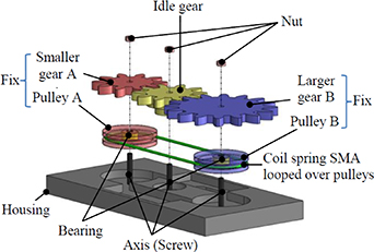
Figure 6. Synchronized pulley engine with two active pulleys and one idle pulley [76].
Download figure:
Standard image High-resolution image2.1.2. Unsynchronized pulley engines type.
In this class of SMA heat engine, the two pulleys rotate independently. The only connection between them is the actuating SMA element. The pulleys are free to rotate independently of others. An example is shown in figure 7. Like a synchronized pulley engine, this type of engine also has a joining problem and drag loss depending on the medium used, but it has the advantage of less material usage due to the absence of a synchronizing system. And also, a double rotation direction.

Figure 7. Unsynchronized pulley engine [77].
Download figure:
Standard image High-resolution imageTobushi et al investigated the unsynchronized SMA heat engine and analyzed its output power [78]. This engine operates between hot water and cold air at room temperature. Sometime to increase the power output of an SMA engine, the surface area is increased by using a rectangular SMA belt [45, 79]. Tanaka constructed and analyzed an unsynchronized rectangular belt type NiTi SMA heat engine. The engine is designed to have two active pulleys and one idle in the middle so that it works between hot and cold water. Figure 8 shows this arrangement.
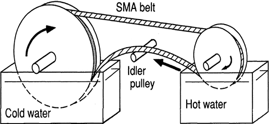
Figure 8. Unsynchronized belt type SMA heat engine [79].
Download figure:
Standard image High-resolution imageThis engine suffers from friction torque loss at the idle pulley due to the bending of the SMA belt around the idle pulley and dragging force through the water media. In some engines, multiple SMA belts are used to increase its output performance. Sato et al used this kind of design to analyze SMA engine performance [77]. The engine consists of two multi-grooved pulleys. A driver Pulley with a larger diameter and a driven smaller one, carrying many NiTi SMA wires. The engine works between hot water and cold air media. Figure 9 shows the design.
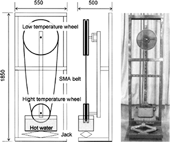
Figure 9. Unsynchronized SMA heat engine [77].
Download figure:
Standard image High-resolution imageKumar et al investigated an SMA engine with an emphasis on high efficiency and low-grade temperature for the conversion of thermal energy to electrical [80]. In this research, an unsynchronized two pulley Niti SMA heat engine is used. The engine is designed by planting arrays of NiTi SMA engines on a pipe of wastewater to convert thermal energy to mechanical for maximizing output power. Ibrahim et al also used this type of design for the generation of electricity [81]. A smaller driving pulley is dipped into the hot water while the larger driven pulley is positioned outside, and is connected to a generator for electricity generation.
For the first time, an unsynchronized SMA motor driven by light is introduced [82]. The engine uses NiTi SMA wire that is initially trained to be straight, and then it is formed into a loop and put around two wheels. The wire changes its radius of curvature as the engine is rotating. At the point where the SMA wire is leaving the wheel, light is irradiated. This will cause the SMA wire to undergo a phase transformation and to straighten, causing the wheel to rotate, as shown in figure 10.

Figure 10. SMA light-driven motor [82].
Download figure:
Standard image High-resolution imageThe advantage of this type of engine is that there is no retarding drag force because there is no physical contact between the driving element and the heat source. The direction of rotation can be easily be changed by changing the position of the irradiating portion.
2.2. Field engines
In this category, the engine operates against a recovery force like gravity and magnetic field. With the gravitational field, as the NiTi SMA is heated, it will contract and increase the mass distribution density of that section, which in turn changes the net distribution of gravitational force acting on the wheel thus, causes the engine to rotate. Figure 11 shows this arrangement.
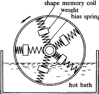
Figure 11. Field SMA heat engine [83].
Download figure:
Standard image High-resolution image2.3. Crank engine
This kind of engine is of two types, the axis center, and the offset center type [27, 69]. In both types, the engine converts the reciprocating linear motion of the SMA element into a rational motion, by connecting an SMA actuating element eccentrically to the output shaft. In the axis center type, the crank type of SMA heat engine has two crankshafts, and SMA elements are attached to the crankshafts at different locations along the shaft. The engine rotation is made in one direction by synchronizing gears or timing belt. Figure 12 shows an example of this engine type.

Figure 12. Schematic diagram of the twin crank engine [27].
Download figure:
Standard image High-resolution imageThe spring length is shorter than the distance between the crankshafts, so it is extended to fit. In most cases, the engine uses hot water and cold air as working media. As the SMA spring enters hot water, it contracts while the other spring in air extends, thus force the shaft to rotate. Iwanaga et al designed this type of engine and used NiTi helical spring as the actuating element [84]. So also, Zhu et al used this kind of design in their investigation [69], so did Churchill et al and Franco et al [72, 85].
Offset center SMA heat engine is another example of an SMA crank heat engine. Ridgway M Bank first invented this type of engine in 1973 at Lawrence Berkeley Laboratory, University of California [3]. In this design, the engine has a flywheel with 20 Nitinol SMA wire loops attached to the spoke of an offset wheel-hub. The hub eccentricity caused the NiTi SMA wires to stretch more on one side of the wheel than the others. The Nitinol wires then contracted and straightened as they entered hot water and reverted to the original shape in cold water; thus, the wheel rotated continuously, as shown in figure 13. The engine can operate horizontally or vertically. The horizontal one is shown in figure 13. It uses hot water and cold water, but it has a serious problem of mixing the water, causing the engine to slow down readily. In contrast, the vertical one usually uses hot water and cold air, as illustrated in figure 14.

Figure 13. Horizontal design of offset SMA heat engine by Ridgway [3].
Download figure:
Standard image High-resolution image
Figure 14. Offset vertical SMA crank heat engine [35].
Download figure:
Standard image High-resolution imageAn offset NiTi SMA engine is proposed [83] to be used for space missions. This engine uses solar energy instead of hot water as a source of energy. The engine has some NiTi SMA springs attached to its wheel circumference and its center. A cover is provided for cooling purposes. As the NiTi SMA spring is exposed to sunlight, it will contract, and this will cause the center to shift. When the spring moves into the cover, it cools down and extends. Thus the engine rotates. Tobushi et al investigated an offset center crank engine with the aim of improving its performance [78]. Hot water and cold air are used as working media. Tobushi et al further modified this type of engine to a tilt-disk offset crank SMA heat engine [86]. This machine has two separate disks connected by some NiTi SMA springs at a tilt angle. The two discs are immersed in hot water and supported at their center each. When the springs pass through the hot water, they contract, and when they come out of the water, they will be cooled by cold air and extend, thus rotate the engine. Also, Verma et al designed a NiTi SMA crank offset center heat engine [87] for the purpose of using exhaust gas from the vehicle as a heat source. The engine is shown in figure 15.

Figure 15. Offset center heat engine [87].
Download figure:
Standard image High-resolution imageGenerally, all these offset crank engines have the advantage of using less space and material as compared to those pulley engines.
2.4. Reciprocating category
In this type of SMA heat engine, the reciprocating motion of SMA is used to rotate the engine. Sakuma and Iwata produced a reciprocating NiTi SMA heat engine [20], as shown in figure 16. This engine has two NiTi SMA wires that were attached to a lever arm at the top and fixed at the bottom. The lever has a fulcrum at the center and is extended at martensite phase temperature and put in a heat exchanger. When one of the NiTi SMA wires is heated at high austenite finish temperature, it will contract. Whilst the other one is cooled at a temperature lower than the transformation finish, it will be extended by the NiTi SMA wire at a higher temperature. By switching the heating and cooling of the two wires, the system produces a reciprocating motion.
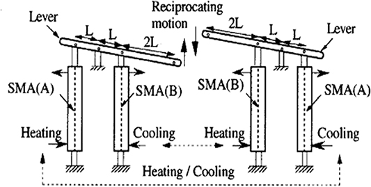
Figure 16. Schematic diagram of a reciprocating heat engine using SMA [20].
Download figure:
Standard image High-resolution imageMizutani et al used this principle and further extended it by incorporating a hydraulic system to generate electrical energy [88]. In their engine, the lever link is connected to a piston that pumps hydraulic fluid into a motor, which further rotates a generator for electricity generation. Kaneko et al developed a reciprocating SMA heat engine that works by the alternating supply of cold/hot water supplied to specially designed automatic valves [89]. In this engine, NiTi SMA wire is connected to a chin and sprocket system, and a flywheel is attached to it using a spindle, as shown in figure 17. The reciprocating movement of the arms is caused by the contraction and relaxing action of NiTi SMA wire, which finally rotates the sprocket. In this engine, there is some complication, and it uses more material.
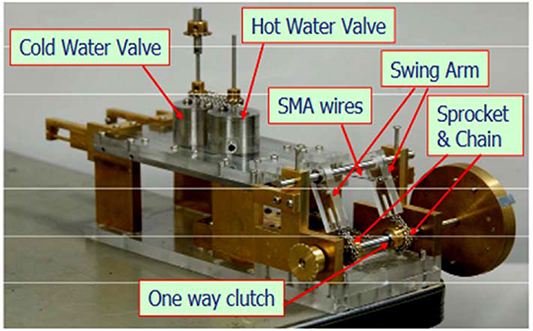
Figure 17. Reciprocating SMA engine [89].
Download figure:
Standard image High-resolution image2.5. Miscellaneous category
In this category, any other type of SMA heat engine is discussed here. This includes a swashplate, sequential engine, and many more. Jardine developed a swashplate heat engine, as shown in figure 18 [90]. This engine has two plates attached at a tilt angle and separated at a distance using NiTi SMA springs. When the spring is heated in an extended state, it generates restoring forces consisting of radial and tangential components. The tangential component turns the engine and produces a rotation motion of the engine. This type of engine has a simpler design with less material use and space.
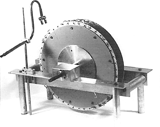
Figure 18. Swashplate SMA heat engine [90].
Download figure:
Standard image High-resolution imageA design called Novel heat engine is also adopted. The basic design approach of this engine is a rotation based on heating NiTi SMA wire loop around some pulley cylinders. Cylinders form another cycle around a hot exhaust pipe. When the hot gases pass through the exhaust pipe like that of the moving the vehicle, heat is transferred to the NiTi SMA wires, which will create a thermal contraction and produce a torque that eventually generated power. An example of this type of engine is reported by Browne et al [26]. Alex et al presented a design for an automatic buoyancy of unmanned underwater vehicle [91]. The working principle of this engine is to use the Archimedes principle. As the engine operated in deep ocean water with low temperature, the NiTi SMA extended into de-twinned martensite state by a parallel steel compressive spring attached to it. And this resulted in a moving a piston in a cylinder, thus increased the volume of a dry chamber and caused a larger buoyancy force. At the ocean surface where the water temperature is high, the NiTi SMA spring will contract due to martensite-austenite transformation and reduce the volume of the dry chamber. Therefore, the device will tend to sink [92]. Cho et al developed another type of heat engine using spiral NiTi SMA spring [45]. In the design, one end of a helical NiTi SMA spring is attached to a shaft at the center axis of a container, and the other end to the surface of the container. In the beginning, the spiral SMA spring is cooled, and in a martensitic state, it will be winded up. As the spring is heated up in an austenitic state, it will recoil in the reverse direction, thus turns the engine. According to the author's analysis, the design has an advantage over conventional SMA engines that the system can quickly be cooled or heated up uniformly, and the fatigue-life of NiTi SMA is longer. But this engine type is a little bit complicated. Another kind of SMA engine that falls in this category is the tether heat engine [93]. The engine used energy from sunlight to operate. A temperature variation will be created in a NiTi SMA film due to a periodic variation of the incident sunlight angle and cause the engine to rotate. The specific design makes the engine limited for space missions only. Its schematic diagram is shown in figure 19.

Figure 19. Tether SMA heat engine [93].
Download figure:
Standard image High-resolution image
2.6. Heating and cooling method in different media
NiTi SMA heat engines use different methods and different media for heating and cooling the system that drives the engine. From various references, four major means of heating and cooling methods are identified.
- (a)Hot water and cold waterHere the NiTi SMA element passes through hot water to heat up and contract, then later passes through cold water to cool down and relax. Many researchers use this method to drive their engines, such as Tanaka [79] and Martin et al [75]. But this method has a problem of mixing up the hot water with a cold one readily, which tends to lower the performance of the engine.
- (b)Hot water and cold airHere the NiTi SMA element passes through hot water to heat up and contract, then later passes through the cold air to cool down and relax. Depending on the ambient temperature, sometimes a blowing fan is incorporated to increase the cooling rate. This method can be seen in this references [26, 37, 72].
- (c)Hot gas or air and cold airHere hot air or gas is used to heat the NiTi SMA element. Usually, cold air is used for cooling. Verma et al used this method to drive their SMA crank heat engine [87]. Exhaust hot gas from the vehicle was used for heating while the surrounding cold air was used for cooling, as in Browne et al engine [26].
- (d)Thermal radiation and cold airHere heat from either sun or other radiation like laser source [82], is used to heat the NiTi SMA element, and the cold air is used for cooling. Sometimes a Fresnel lens is used to concentrate the heat. Example of this type of engine is seen in the tether heat engine [93].To clarify different heating and cooling methods comparison between the advantages and disadvantages of different SMA engines reported in references is presented in table 1, as follows.
Table 1. SMA heat engines based on the design concept.
| Engine type | Working medium | Advantage | Disadvantage | Material | Author |
|---|---|---|---|---|---|
| Crank | Hot water and cold air | − Small space | − Drag loss − Fluids mixing | Not stated | Ridgway M Bank [3] |
| Synchronized | Hot water and cold air | − Reliable direction | − More material − Single direction | NiTi | A D Johnson's [35, 70] |
| Synchronized | Hot water and cold air | − Reliable direction | − More material − Single direction | Nitinol | John J Pachter [73] |
| Synchronized | Light radiation | − No drag loss | − More material needed − Single direction | Nitinol | Hayashida et al [74] |
| Unsynchronized | Hot water and cold air | − No drag loss | − Fluids mixing − Need space − single direction | -NiTi | Tobushi et al [78] |
| Unsynchronized | Hot water and cold water | − Reliable direction | − Drag loss − Fluids mixing − Need space − Single direction | NiTi | Tanaka [75] |
| Miscellaneous | Hot water and cold air | − Small space | NiTi | Jardine [90] | |
| Crank | Hot water and cold air | − Small space | − Drag loss | NiTi | Tobushi et al [86] |
| Reciprocating | Hot water and cold water | − Flexible due to involvement of hydraulic fluid; | − More material and construction technique required | Not stated | Mizutani et al [88] |
| Reciprocating | Hot water and cold water | − No fluid mixing | − More material and construction technique required | TiNiCu | Sakuma and Iwata [16] |
| Crank | Hot water and cold air | − Small space; | − Dag loss | SMA | Tobushi et al [83] |
| Miscellaneous | Sun radiation | − No drag loss | NiTi | C Bombardelli and C Menon [90] | |
| Unsynchronized | Hot water and cold air | − Bi-direction | − Drag loss − Fluids mixing − Need space − Single direction | Not stated | Sato et al [77] |
| Unsynchronized | Light | − No drag loss − Bi-direction | − Two wavelengths needed | Nitinol | H Okamura [77] |
| Reciprocating | Hot water and cold water | − No fluid mixing | − More material and construction technique required | Not stated | Kaneko et al [89] |
| Miscellaneous | Exhaust hot air and cold air | − High-speed complexity | Not mention | A L Browne et al [64] | |
| Synchronized | Hot water and cold water | − Reliable direction | − More material involved − Need space − drag loss − Fluids mixing − Single direction | Nitinol | Martin et al [70] |
| Synchronized | Hot water and cold air | − Reliable direction | − Drag loss − Fluids mixing − Need space − single direction | Nitinol | C B Churchill and J Shaw [69] |
| Synchronized | − Small space − Mixing of the fluid − Need space − single direction | − More material involved − Drag loss | Not stated | Aono et al [76] | |
| Miscellaneous | Warm water and cold water | Not mentioned | Alex et al [91] | ||
| Miscellaneous | Warm water and cold water | − Easily be cooled or heated up uniformly − The fatigue life of SMA is longer − Less space needed | − External winding force is required | NiTi | Cho et al [45] |
| Crank | Exhaust gas and cold air | − Small space | − Small space | Not stated | Verma et al [87] |
| Unsynchronized | Hot water and cold air | − No drag loss | − More material involved − Fluids mixing − Need space − Single direction | Nitinol wire | Ibrahim et al [81] |
| Unsynchronized | Hot water and cold air | − No drag loss | − More material involved − Fluids mixing − Need space − Single direction | Nitinol | Kumar et al [80] |
Table 1 shows various types of NiTi SMA engines and their attributes, with about 24% synchronized heat engines, 28% unsynchronized heat engines, 16% crank heat engines, and 20% miscellaneous heat engines. It can be seen that the unsynchronized SMA heat engine is more popular due to its simplicity and less material used.
3. Modeling of NiTi SMA engine
For the modeling of NiTi SMA heat engines, there are various methods proposed, and many models are based on the constitutive models for NiTi SMA material [94]. For the energy conversion and the actuation of the NiTi SMA heat engine [95], some models are proposed based on existing theories [96], while some others are based on the working mechanism of the NiTi SMA heat engine or the combination of the two.
3.1. Driving model based on the working element
Hayashida et al developed a prototype thermo-turbine synchronized NiTi SMA heat engine for space missions [74]. For the analysis, the output work and power could be calculated as follows:
where γ, β, α, and δ are material constants, ΔT is the change in temperature and t is the time taken. This model is a rather simple one, and it is straightforward to do the calculation once the material constants are given. Zidtkowski proposed a theoretical thermo-mechanical driving model in 1993 for a solid-state NiTi SMA engine [97]. The thermo-dynamical models are R model (Maxwell model),  ; RL model (Raniecki-Lexcellent-Tanaka model)
 ![${\sigma _1}\left( {T,z} \right) = {{\rho } / {\gamma }}\left[ {{\phi _{\text{it}}}\left( T \right)\left( {1 - 2z} \right)} \right] - \pi _0^f\left( T \right) + {k^{\left( 1 \right)}}\left( z \right) - {k^{\left( 1 \right)}}\left( {{z_{\text{min}}}} \right)$](https://content.cld.iop.org/journals/0964-1726/30/1/013001/revision3/smsabc6b8ieqn2.gif) and Muller-Xu-Fedelich- Zanzotto model, which are based on stress–strain (σ–
and Muller-Xu-Fedelich- Zanzotto model, which are based on stress–strain (σ– ) for CuZnAl alloy.
 ![$\scriptstyle{{\sigma _{\text{AM}\left( \text{T} \right) = - }}{{\rho } / {\gamma }}\left[ {T\Delta {s^*} - \Delta {u^*} + u_0^k} \right),{\text{ }}{\sigma _{\text{MA}\left( \text{T} \right) = - }}{{\rho } / {\gamma }}[T\Delta {s^*} - \Delta {u^*} - u_0^k ]}$](https://content.cld.iop.org/journals/0964-1726/30/1/013001/revision3/smsabc6b8ieqn3.gif) where
where  is the stress during austenite-martensite transformation, Zmin
is minimum transformation, T is temperature,
is the stress during austenite-martensite transformation, Zmin
is minimum transformation, T is temperature,  are material constants, respectively; ρ is the density of the material and η is the efficiency. The above mentioned models are not proven practically yet, their accuracy and applicability can not be take for granted. Zhu et al developed a twin crank heat engine and NiTi SMA spring is used as the working element of the engine [69]. The driving model for the engine is proposed based on a model for the NiTi SMA helical spring. Parameters such as the number of turns, length of the spring, and wire diameter of the NiTi SMA spring and NiTi SMA wire twisting angle are considered in constructing the driving model. The driving moment is obtained as
  , where M represents the moment, R is the radius of the NiTi SMA spring, r is the radius of the NiTi SMA wire, γ is the shear strain, and τ is the shear stress of SMA. This is also a simple model. Geo and Huang proposed a solar power offset-center crank NiTi SMA heat engine for space missions [83]. The driving force of the engine is modeled as:
where F stands for force, k is the stiffness of the NiTi SMA spring, I is the moment of inertia, and δ stands for NiTi SMA length. Brown et al developed a simple driving model for their synchronized prototype NiTi SMA heat engine [26]. The model is constructed based on the transformation properties of the working material.

where W is work done by the engine,  is austenite recovery stress,
  is martensite de-twinning stress,
  is austenite stress,
  is martensite pre-strain,
  is the final stain, and ρ is the density of NiTi SMA material. In the model developed by Franco et al for NiTi SMA-based crank heat engines [98], the actuation mechanism is based on the NiTi SMA spring length L(t), and its stretch ratio λ(t), is expressed as a function of rotation angle ϕ(t) as shown below:
This mechanism is based on the properties of NiTi SMA spring that it has austenitic contraction in warm water and martensitic stretching in cooling water. Aono et al used a synchronized pulley with a coil NiTi SMA driving belt in microfluidic MEMs (micro-electro-mechanical motor) for optimization purposes [76]. The driving model is based on the assumption that heat transfer between NiTi SMA and the liquid is instantaneously compared to the dynamical response of the heat engine. Newton's law was employed to model the rotation around the center of gravity. The output torque is formulated as:
where δ is the ratio of the shear modulus of rigidity, ζ is the ratio of pitch radii between the gears, and I is the ratio of initial displacement to the natural length. Alex et al designed a NiTi SMA buoyancy engine for unmanned underwater vehicles [91, 92]. The engine driving model is constructed by employing Archimedes principle, and is expressed as:

 , where k is a constant and Δy is NiTi SMA spring length. In a Tether NiTi SMA heat engine developed by Claudio et al, the following equations are used as operational force and work done by the system [93].

where Fmax is a maximum force,  is maximum operational stress, and
  is the change in force generated, W is work done, and Δl is the change in NiTi SMA length. The model is also simpler, and those model parameters are derived using the NiTi SMA element properties.
3.2. Driving model based on both working element and engine geometry
Sato et al developed an unsynchronized pulley engine [77, 99]. The driving model is based on the distortion energy theory associated with the vibration of the NiTi SMA belt as the engine rotates, and the derived model is as follows:
where  is the output wheel driving torque, R is the radius of the low-temperature wheel, r is the radius of the high-temperature wheel, E is young's modulus of SMA belt, I is the cross-sectional second-order moment of SMA belt, and J is the moment of inertia. A swashplate NiTi SMA heat engine is developed by Jardine [90], and its driving power is modeled as:

where P is the power, g is gravity constant, M is the effective mass of the NiTi SMA element, and r is the axle radius. Tanaka developed an unsynchronized two pulleys driven NiTi SMA heat engine [79], and the output torque is formulated as:
where T is the torque of the engine, Rc and Rh are the radii of cold and hot pulleys, and M1, M2, M3, and M4 are the moments at different locations along the NiTi SMA belt. In a synchronized SMA heat engine, Churchill et al used NiTi SMA spring as a driving element, and the model is formalized based on the driving pulley [72].
where Me is the external moment, Mf is frictional losses, a is the pulley diameter, TH and Tc are hot and cold side SMA tension belt respectively, and b1 and b2 are the timing gear radii.
4. SMA heat engine performance
Engine performance is the measure of how well an engine operates in converting one form of energy to another [100]. For the SMA heat engine, engine performance is defined as power output per mass of active SMA material [26]. It is easy to see that the most important parameters to evaluate heat engines are the output power and the efficiency of the engine.
4.1. Output power of the SMA heat engine
Output power P of an engine can be defined as the energy or work done by that engine per unit time. The unit usually adopted is the watt, which is equivalent to joule per second (J s−1). In measuring the power of an SMA heat engine, important parameters like angular speed (ω in rad s−1), the number of revolutions per minute (rpm) N, Torque ţ in Nm are usually considered. Another parameter, like temperature T, is also essential. From literature, depending on the size, the output power of an SMA engine can range from 0.2 to 32 watt at maximum [25]. Researches show that the power of an engine increases with the number of revolutions per minute until a pick value is reached, then decreases significantly [25].
4.2. Efficiency and thermodynamics thermal recovery of the SMA heat engine
The thermal efficiency of an SMA heat engine can be defined as a measure of performance by taking a ratio of energy output to the energy input from a source, usually expressed in percentage [71, 80]. This can be thermal-mechanical or, in some cases, thermal-electrical efficiency . In thermodynamics terms, efficiency is defined as the proportion of energy conversion from thermal form to mechanical or electrical ones. It is expressed as follows:  where W is the work done, and Qin is thermal energy input. For SMA heat engines, theoretical efficiency could range from 1% to 7% [50]. In order to estimate the thermodynamic efficiency of an SMA heat engine, an idealized thermodynamic cycle is always appropriate for the consideration. In most cases, the Carnot cycle is a very convenient candidate thermodynamic cycle, and it is a stimulating ideal for developing a heat engine to take the Carnot cycle as a reference. However, the real heat engines are not reversible. A report shows that the thermal efficiency of an SMA engine is around 20% of that of a Carnot engine [79]. Factors like narrow hysteresis loop of SMA, high rate of cooling SMA, zero-slip of SMA belt are among the factors that can increase the operating frequency of SMA material, thus increasing the efficiency of the engine [26]. Other factors might include the temperature of cold and hot reservoirs, the SMA latent heat of transformation, the specific heat of SMA element, the applied stress, the material pre-straining, the mode of deformation of the material, the SMA geometry (size and shape), the SMA structural condition like grain size, and many more [101].
Researchers reported some significant output power by using different types of engine design. The first early SMA heat engine is designed by Ridgway Banks, which is a crank NiTi SMA heat engine and is able to produce about 461.94 N of force, 70 rpm of rotation speed, and about 0.5 W of electricity [35]. In research presented by Salzbrenner R, the maximum amount of work produced by two types of SMA (Ni-40% Ti) heat engines (Stirling and Ericsson) working between room temperature of 25 °C–190°°C is 58.2 J mol−1 per cycle, and its efficiency is around 0.4% [102]. As for the prototype thermo-turbine synchronized heat engine developed by Hayashida et al, the output power is 0.050 W [74]. A swashplate NiTi SMA heat engine developed by Jardine gave an output power of 0.166 W at 55 rpm, with a temperature difference of 80 °C [90]. Tanaka used a pulley driven NiTi SMA heat engine and produced a maximum power output of 0.53 W at a temperature of 90 °C experimentally against the predicted output power of 0.2 W [79]. Mizutani et al also used reciprocating SMA heat engine with a hydraulic system, and the output power is presented as 0.277 W, with a rotation speed of 96 rpm [88]. Tobushi et al developed a tilt-dick offset crank heat engine, and its maximum power output is around 0.49 W at 75 °C and velocity of 10 m s−1 [86]. In their report, Zhu et al [69] analyzed a twin crank NiTi SMA heat engine, and the estimated output power is 2 W at a speed of 75 rpm, and a temperature of 75 °C. The maximum efficiency is recorded as 0.85%. The efficiency of the engine increased as the rotation speed decrease. The output torque, power, and heat efficiency increased with the decrease of the SMA spring length only in low-speed cases and is contrary at high speed. It is also reported that, because of the stress–strain distribution upon torsion, using NiTi SMA wire will be more efficient than using NiTi SMA spring as a driving element. The conclusion is drawn that overall power and torque will be increased with an increase in temperature. According to the research, the higher the temperature of the working medium, the higher the rotation speed of a NiTi SMA engine. In the proposed solar-driven crank NiTi SMA heat engine for space mission, Gao and Huang's engine produced an estimated power output of 0.0095 W at 0.0035 rad s−1 under temperature of 52 °C and efficiency of 8.98% [83].
The number of NiTi SMA belt used in an SMA heat engine also increases the final power and efficiency. As indicated in the research presented by Sato et al, the output power is measured between 0.02 W using one NiTi SMA belt, and 0.025 W using three NiTi SMA belts. Maximum electrical power is measured as 1.16 watt (3.5 V·0.33 A) using five SMA belts at 89 °C. The maximum efficiency is calculated as 11.3% [77].
In the investigation performed by Brown et al on a synchronized pulley NiTi SMA heat engine, it is found that the cooling rate is another factor affecting the efficiency of the engine [26]. They reported a maximum output power of about 0.110, 0.082, and 0.061 W g−1 at a velocity of 4.8, 3.5, and 2.2 m s−1, respectively. Maximum efficiency of 8% is reported at a temperature difference of 200 °C by Churchill et al in their synchronized NiTi SMA heat engine [72], and the output power is 0.116 W g−1. Javakhishvili et al reported that the martensite rotor engine is more efficient than non-rotor martensite [71, 72]. A reciprocating NiTi SMA heat engine developed by Kaneko et al is able to produce 0.1 watt at 30–40 rpm using a 0.3 mm NiTi SMA wire at a temperature difference of 95 °C [74, 89]. Javakhishvili et al obtained a thermal efficiency of 1.5% by using a synchronized SMA heat engine [71]. In a model developed by Franco et al for SMA-based crank heat engines [98], the maximum output power is estimated at around 0.180 W g−1 at a maximum temperature difference of 95 °C and at a speed of 15 rpm. In a study by Franco et al, NiTi SMA based on a crank heat engine developed a maximum output power of 0.190, 0.170, and 0.160 W at a maximum temperature difference of 95, 90, and 85 °C, respectively [85]. This engine has a maximum efficiency of around 1% at 90 °C and 4.3 mm stretch ration. Furthermore, the efficiency decreased with an increment in rotational speed.
Some researchers tried to improve the performance of the SMA heat engine by using a taped-SMA element, inspired by the idea of increasing the surface area, which allows easy heating and cooling of the driving SMA element. Also, the rate of cooling could be increased by incorporating a cooling system. Cho et al used this idea and developed a synchronized pulley-tape NiTi SMA belt heat engine and incorporated a cooling mechanism, and the engine is able to generate power of 0.09 W at a temperature difference of 60 °C [45, 103]. According to this research, factors like heating and cooling rate, and SMA wire size, determines the final output power. Verma et al presented a crank NiTi SMA heat engine that was able to generate 0.3 W of power at an engine speed of 165 rpm using vehicle exhaust gas as a heat source [87]. When hot water was used in the second experiment as a source of heat, the engine performance was reduced with the highest speed of 46 rpm. Ibrahim et al conducted a research project using an unsynchronized pulley SMA heat engine, and they achieved 405 mV of electricity at 400 rpm and maximum efficiency of 2.6% at a maximum difference temperature of 90 °C [81]. Kumar et al used an unsynchronized pulley engine, and its rotational speed and torque are measured to determine the power of the engine [80]. The engine is designed for the generation of electricity and is able to generate 36 W kg−1 equivalent to 234 KW m−3 of active material. The engine performance is measured with 0.0125 W output power at 69 °C and 0.026 W at 80 °C. The ratio of mechanical power to weight is obtained to be 0.052 W kg−1, and the maximum electrical power is 0.0088 W at 70 °C and 0.018 watt at 80 °C. The electrical power density is 36 W kg−1. The relative efficiency is calculated as 11%. A light-driven unsynchronized pulley SMA motor used 0.3 mm diameter NiTi SMA wire, and the motor generated 4 Watt output power at 135–140 rpm [82].
Some researchers reported only the efficiency of their SMA heat engines. Theoretically, the thermal efficiency of the solid-state NiTi SMA heat engine is evaluated and estimated to be 20% by Golestaneh et al [101]. Javakhishvili et al, in their research, reported a theoretical maximum efficiency of 1.4%. This value is very low as compare to the Carnot efficiency of 35.6% [102]. Zidtkowski calculated the SMA heat engine efficiency of 0.4%. Theoretical thermal efficiency for solid-phase SMA generator is presented [97]. This reported that the higher the stain value of SMA material, the higher the efficiency of the SMA heat engine. In a theoretical analysis by Zidtkowski, R model, Muller-Xu-Fedelich-Zanzotto model, and RL model, they investigated the efficiency of a solid-state engine for three SMA materials [97]. The efficiency for solid-state SMA heat engine using SMA CuZnAl mono-crystalline is presented in table 2:
Table 2. Efficiency of solid-state SMA heat engine using CuZnAl mono-crystalline.
| T1 = 293 K, ΔT = 50 | |||
|---|---|---|---|
| % | R model | RL model | Muller-Xu-Fedelich-Zanzotto model |
 (Real) (Real) | 3.09 | 2.51 | 2.85 |
 (Regeneration) (Regeneration) | 14.58 | 11.51 | 13.48 |
 (Carnot) (Carnot) | 14.58 | - | |
| T1 = 293 K, ΔT = 80 | |||
 (real) (real) | 3.32 | 2.94 | 3.32 |
 (Regeneration) (Regeneration) | 21.45 | 19.1 | 20.48 |
 (Carnot) (Carnot) | 21.45 | - | |
From table 3, the SMA crank engine by H. Okamura generated the highest power output of 4 watt. And, Sato et al unsynchronized SMA pulley engine is the most efficient with the value of 11.3% efficiency.
Table 3. Summary of the performances of some of the SMA heat engines.
| Engine of type | Temperature (oC) | Speed (rpm) | Max. output power (W) | Efficiency (%) | Author |
|---|---|---|---|---|---|
| Miscellaneous | 100 | 55 | 0.166 | Not reported | Jardine [90] |
| Unsynchronized pulley engine | 90 | 250 | 0.53 | Not reported | Tanaka [79] |
| Reciprocating engine | Not reported | Not reported | 0.277 | 1 | Mizutani et al [88] |
| Crank engine | 75 | 10 | 0.49 | Not reported | Tobushi et al [78] |
| Crank engine | 90 | 75 | 2 | 0.85 | Fei et al [42] |
| Twin crank | 70–90 | 75 | 1.5–2.125 | 0.5–2.3 | Zhu et al [69] |
| Crank engine | 52 | 35 | 0.0095 | 8.98 | Gao and Huang [83] |
| Unsynchronized pulley engine | 89 | Not reported | 1.16 | 11.3 | Sato et al [77] |
| Crank engine | Above 60 | 140 | 4 | Not reported | H Okamura [83] |
| Synchronized pulley engine | 160–200 | Not reported | 0.116 | Not reported | Churchill et al [72] |
| Synchronized pulley engine | 200 | Not reported | 0.110, 0.082 and 0.061 | 8 | Brown et al [82] |
| Reciprocating engine | Around 95 | 30–40 | 0.1 | Not reported | Kaneko et al [89] |
| Twin crank | 95,90,85 | 15 | 0.190, 0.170 and 0.160 | 1.2 | Franco et al [98] |
| Unsynchronized pulley engine | 60 | Not reported | 0.09 | Not reported | Cho et al [45] |
| Crank engine | 150 | 165 | 0.3 | Not reported | Verma et al [87] |
| Unsynchronized pulley engine | 90 | 400 | Not reported | 2.6 | Ibrahim et al [81] |
| Unsynchronized pulley engine | 69–80 | Not reported | 0.0125 | 11 | Kumar et al [80] |
4.3. SMA heat engine limitations
From literature, it is observed that the efficiency of the SMA heat engine is less than 10% [45], and this is the major drawback of this type of engine. Other SMA engine challenges can also exist. It ranges from narrow thermal Hysteresis at a suitable temperature range for heat source utilization, high transformation strain, and forming of SMA for continuous loop [26]. Challenges from the device can be demanding for a high rate of heat transfer, heating, and cooling rate [35], device design, and integration with power system hardware, energy storage, transmission, and mechanical tolerances. Low Carnot and thermodynamics efficiency, material durability and cost, lack of established working model [71], complexities in the working fluid are some of the current problems of low-grade thermal energy extraction (near or below 100 °C), which hold back the commercialization of SMA heat engine [37]. Among the early heat engine, the Ridgway Bank heat engine did not employ uniaxial deformation, which gives high power density and efficiency, due to insufficient use of SMA wire. Also, due to hydrodynamic friction, the engine suffered from thermal and mechanical parasitic losses [35]. SMA engines that deal with water to air heat transfer suffer from slow speed as compared to those that transfer from hot water to cold one [79]. One of the drawbacks discovered in a model developed by Franco et al for SMA-based crank heat engines is that its thermodynamic efficiency decreases by increasing rotational speed [98]. In contrast, for good engine performance, the opposite is supposed to happen. Generally, for belt-driven SMA heat engines by hot water, drag is created as it passes through the water. This reduces overall engine efficiency [82]. SMA heat engine is generally cooled by water or air, but one of the drawbacks of this practice is that the latent heat discharge during cooling cannot be used [20]. In the pulley engine with SMA belt, there is friction torque loss due to the bending of SMA belt around both the active and, in some cases, the idle pulley [79]. Another problem with many belt SMA heat engines is that, at the joint where the belt of wire is connected, the property of SMA changes. This brings the problem of stoppage or interruption during the engine operation.
For the light-driven SMA engine, one of its drawbacks is, it requires two wavelengths to operate [82]. Some engineering difficulties were aroused by Claudio et al regarding a proposed tether SMA heat engine for space power generation. This is as follows: (a) design of a dynamic device that allows the SMA film to move from high to low tension to achieve good mechanical efficiency. (b) Design of a device that will enable the film to move from an illuminated condition to a fully shaded one [93].
4.4. Summary
A summary is drawn based on SMA heat engine popularity and performance.
- Several engine driving equations are reviewed, and it is found that some of them are based on both SMA material and engine geometries like pulley diameter, while others are just based on SMA material alone.
- From the reviewed research, it is seen that the pulley type NiTi SMA heat engine design is more popular. This is because of its simplicity and higher power output.
- For the crankshaft NiTi SMA heat engine, torque and power output increase with the increase of pairs of opposing cranks. Output torque decreases with the increase of rotational speed.
- In the SMA heat engine, factors like heating and cooling rate and NiTi SMA wire size determine the final power output. An increase in cooling and heating rate would increase the power output.
- Decreasing the SMA wire sizes would decrease the heat capacity. Thus, the critical temperature is reached quickly. Therefore using many wires with smaller diameter increases the power output.
- For SMA spring-based heat engine, its power output, torque, and thermodynamic efficiency increase with the increase in stretch ratio because of higher deformation, which gives higher shape recovery capacities. However, it affects the fatigue life of the SMA spring element.
- It is also reported that the martensite rotor engine is more efficient than non-rotor martensite heat engines.
- The output power of the SMA engine increases with the temperature of the hot water. The range of rotational speed at maximum power out is wide. The power output increase with a number of SMA wire loops.
- Many types of researches are presented, with about 24% synchronized SMA heat engines, 28% unsynchronized SMA heat engines, 16% crank SMA heat engines, and 20% miscellaneous SMA heat engines. It is found that H. Okamura's crank SMA heat engine generated the highest output power of 4 watt. Also, Sato et al unsynchronized SMA pulley engine is the most efficient with the value of 11.3% efficiency.
5. Conclusion
In this paper, a review of NiTi SMA heat engines is presented right from SMA discovery to date. An attempt is made to trace the development of different kind NiTi SMA heat engine. This consists of their driving model, conceptual design classifications, and their overall performance. It is discovered that the pulley NiTi SMA heat engine is the most popular. The unsynchronized pulley SMA heat engine is more efficient, with 11.3% engine efficiency. Shortcomings and limitations of SMA heat engines are generally identified. And if these are solved, the overall engine performance would drastically be improved, which would make the SMA heat engine a good renewable energy conversion system.