

Abstract
Novel piezo-ionic/magnetostrictive bi-layer composites for new energy generation devices are presented. These structures, fabricated with Metglas® 2826MB ferromagnetic alloys and ionic liquid based PVDF-HFP polymer composites, show an induced electric response as a consequence of the coupling between the magnetostrictive properties of the Metglas® 2826MB and the piezo-ionic ones of the ionic liquid based PVDF-HFP polymer composites. These flexible, simple and low cost structures do not need to be polarized to exhibit an electric response, and show an increased induced voltage as the percentage of the ionic liquid in the PVDF-HFP matrix does. This response is a consequence of the asymmetric deformation caused by the magnetostrictive material on the piezo-ionic composite, which induces a non-uniform distribution of the cations and anions in the polymer matrix. The laminates present a maximum response under the application of a low magnetic fields of 9 Oe, and a normalized magneto-ionic coefficient values up to 550 mV cm−1.Oe for the structure with an ionic liquid content of 30 %. These values are even higher than others obtained with piezoelectric materials based ME composites. The simple fabrication process and potentiality of these new piezo-ionic/magnetostrictive laminates contributes to broaden and improve the state of the art of the energy generation systems.
Export citation and abstract BibTeX RIS
1. Introduction
The development of novel, advanced and functional materials for sensors, actuators and energy harvesting applications has become a challenge in last years within the scientific community [1–5]. Many of the recent efforts have been devoted to fabricate smart and wearable devices able to convert the mechanical energy into electrical one and vice versa, in order to implement them in detection systems of human motion, robotics, rechargeable batteries or power suppliers, among others [6–8]. Over the last years, most of these devices have been based on polymeric and ceramic piezoelectric materials, but the multidisciplinarity of the recent applications requires the introduction of new functionalities.
Recently, materials based on the triboelectric and piezo-ionic effects have emerged as important alternatives. Unlike the traditional piezoelectric elements, materials based on both triboelectric and piezo-ionic effects do not need to be polarized to induce an electric response, which simplifies its fabrication and reduces the cost of the production [9–11]. While triboelectric effect is based on the use of the static charges accumulated on the surface to generate energy, piezo-ionic effect induces an ionic response by separating anions and cations under the application of a mechanical stress. In that way, polymer/ionic liquids (IL) composites appear to be a promising alternative in the area of piezo-ionic materials.
In particular, such composites have been largely explored over the last few years as piezo-ionic actuators [12–16]. This behavior is caused by the separation of different charged ions in the matrix under the application of an electric field that, due to the different ions sizes and mobility, results into a mechanical local strain of the polymer film. However, materials based on the piezo-ionic effect have been hardly explored as sensors for different detecting systems [17]. In this case, the deformation of the material modifies the matrix volume at the microscopic level, altering consequently the ions local concentration [18–21]. Moreover, to the best of our knowledge, the fabrication of micro and nano-generators is still based on piezoelectric and triboelectric devices [22], whereas the potentiality of piezo-ionic materials as energy generators has not been analyzed so far. These novel energy generators can be developed through an asymmetric deformation along the polymer/IL composite.
Among the materials able to show a mechanical deformation under external stimulus, magnetostrictive alloys stand out as one of the most suitable ones. These alloys are usually Fe or Co based metallic glasses that exhibit deformations that range between few parts per million up to 40 ppm at an applied magnetic field of few Oersted [23]. These kind of alloys have been extensively employed with piezoelectric materials, making use of the coupling between magnetostrictive and piezoelectric phases [24–28]. This coupling gives rise to the fabrication of the so called magnetoelectric (ME) laminated composites, which have been used in a wide range of applications such as magnetic field sensors [29], high power converters [30] or biomedical applications [31, 32], among others. However, the exploration of magnetostrictive materials with piezo-ionic composites has not been carried out yet.
In this work, novel flexible bi-layer structures fabricated with a Metglas® 2826MB alloy and [C2mim][NTf2] ionic liquid based PVDF-HFP composite are presented. The fabricated structures have been fully characterized by measuring the induced ionic response under the application of a magnetic field (known as magneto-ionic (MI) response [33]). Furthermore, the MI response has been analyzed as a function of the frequency and of the percentage of IL. For the first time, an induced MI response has been measured in such composites. This response has been obtained at low applied magnetic fields, and its value increases as the percentage of IL does, opening new perspectives in the development of magnetostrictive/piezo-ionic composites for energy generation devices.
2. Experimental
2.1. Fabrication and characterization of the PVDF-HFP/[C2mim][NTf2] composites
The ILs 1-ethyl-3-methylimidazolium bis(trifluoromethylsulfonyl)imide ([C2mim][NTf2]) was purchased from Iolitec (Germany) with stated purity of 98%. Poly(vinylidene fluoride-co-hexafluoropropylene) (PVDF-HFP, SOLEF® 21 216/1001 from Solvay (Belgium)) was used as polymer matrix and N,N-dimethylformamide (DMF) (99.8%) (supplied by Sigma Aldrich) as solvent. This PVDF-HFP copolymer was selected due to their known good mechanical properties[34], as well as its high chemical and thermal stability. The structure of the used ionic liquids, one of most used and studied IL, is shown in the figure 1.

Figure 1. Structure of 1-ethyl-3-methylimidazolium bis(trifluoromethylsulfonyl)imide ([C2mim][NTf2]). The PVDF-HFP/[C2mim][NTf2] composite films were prepared by solvent casting and melting with 0, 5, 20 and 30 wt% content of [C2mim][NTf2].
Download figure:
Standard image High-resolution imageThe different quantities of ionic liquid were dispersed in 6 ml of solvent for 10 min. At that time, 1 g of the polymer was added to the dispersion (corresponding to a polymer: solvent ration of 15:85 in weight) and mixed under magnetic stirring at room temperature to the complete dissolution. Then, the obtained homogeneous solution was spread on a clean glass substrate and melted at 190 ºC for 10 min. Finally, a 40 nm thick gold layer of (45 mm x 6 mm) was deposited onto both surfaces of the PVDF-HFP/[C2mim][NTf2] composites using a Polaron Coater SC502 magnetron sputtering. The final thicknesses of the composites were measured to range from 70 to 100 µm.
The fabricated PVDF-HFP/[C2mim][NTf2] composites were electrically characterized by measuring the dielectric constant and the corresponding losses. Circular Au electrodes of 2.5 mm radius were coated by magnetron sputtering on both sides of each sample. The measurements were carried out in the frequency range of 1000 to 1 000 000 Hz. The capacity and dielectric losses (tg (δ) parameter) of the samples were measured with an Agilent E4980 A Precision LCR Meter instrument. From the obtained data, the dielectric constant (ε') and the a.c. conductivity (σ) were determined.
The mechanical properties of the composites were analyzed by measuring stress-strain curves using a Metrotech MTE-1 from Techlab in the tensile mode. Stress-strain curves were obtained at 5 mm · min−1 in 4 mm wide and 15 mm long samples. From the slope of the measured curves, the Young's modulus was determined through the equation  , where σ and
  are the stress and the strain, respectively .
Finally, the transversal morphologies of the composites were obtained by using a Scanning Electron Microscope (SEM) (JEOL JSM-7000 F) with an accelerating voltage of 5 kV. As it can be directly seen in the image represented in the inset of the figure 2(b), PVDF-HFP and PVDF-HFP/[C2mim][NTf2] composites present a non-porous and uniform morphology, as well as a high transparence.
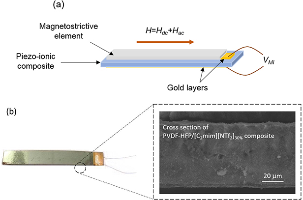
Figure 2. Scheme of a fabricated laminated composite (a) and a picture of one of the fabricated structures (b). The inset on (b) shows a SEM microscope image of the cross section of the PVDF-HFP/[C2mim][NTf2]30 wt% composite.
Download figure:
Standard image High-resolution image2.2. Magnetostrictive materials
Metglas® 2826MB ribbons (with a composition of Fe37Ni42Mo4B17, as reported in [35]) with thickness of 30 µm were used as the magnetostrictive elements of the laminates. Strips of (40 mm x 6 mm) were magnetically characterized by measuring the magnetic hysteresis loop and the magnetostriction curve, from which the corresponding piezo-magnetic coefficient was derived. The first measurements were carried out through a home-made inductive tracer. In that system, the magnetic field was generated by a pair of Helmholtz coils driven by a bipolar power supply (KEPCO BOP 20–20 M) at a given frequency and calculated from the voltage drop across a standard resistor, assuming a conversion factor of 30.4 Oe A−1 [26]. The alloys were placed in the central region between the coils and surrounded by a small air-compensated pick-up coil of 2000 turns. In order to measure the magnetostriction curves of the ferromagnetic strips, the same set-up but with a strain gauge glued on the top of each ribbon was used. A Wheatstone bridge working in half bridge configuration that includes a temperature effect compensation passive gauge was used to measure the elongation of the Metglas® 2826MB strips under an applied magnetic field.
2.3. Fabrication and characterization of the laminated composites
The final bi-layered structures were fabricated by bonding a Metglas® 2826MB strip of (40 mm x 6 mm) to the PVDF-HFP/[C2mim][NTf2] films with a Devcon 5 min epoxy. The gluing process was performed following the Vacuum bagging technique [36]. The composites were placed within a plastic bag, which was subsequently sealed. The air inside the bag was extracted through a valve using a pump, ensuring a homogenous distribution of the epoxy at the interface between the Metglas® 2826MB ribbon and the PVDF-HFP/[C2mim][NTf2] composite. All the composites were cured at room temperature for 24 h. The thicknesses of the epoxy layers were measured to range between 16 and 19 μm for the fabricated composites. Figure 2 shows a diagram (a) and a picture (b) of a bi-layered laminated composite, together with a SEM microscope image of the cross section of the PVDF-HFP/[C2mim][NTf2]30% composite.
Finally, the MI response measurement set-up consisted in a pair of Helmholtz coils with a calibration constant of 19 Oe A−1, which was used to supply the static magnetic field along the longitudinal axis of the composites. An AC field was superimposed in the same direction by small coil of 8.4 Oe A−1 driven by a function generator (HP 33 120 A), giving a net magnetic field of  , being Hdc≫Hac. The induced voltage across the PVDF-HFP/[C2mim][NTf2] composites was continuously recorded by a Lock-In amplifier (Signal Recovery 7280) with a frequency range up to 2 MHz.
3. Results and discussion
As previously mentioned, these proposed novel bi-layered structures are based on magnetostrictive (Metglas® 2826MB) and a piezo-ionic (IL based PVDF-HFP composite) materials. As it is already well known in bi-layered structures based on magnetostrictive/polymeric composites, the application of a magnetic field along the length direction asymmetrically deforms the polymer composite [37]. In the laminates that we present, the PVDF-HFP/IL piezo-ionic composite undergoes this deformation, being the polymer the matrix for the mobile ions of the IL. Thus, the results extracted from the characterization measurements of each element of the composite, as it will be discussed in the following, are essential for a suitable understanding of the induced MI response.
The dielectric constant ('), conductivity (σ) and tg (δ) parameter of the PVDF-HFP/[C2mim][NTf2] composites are represented in figures 3(a) and (b).
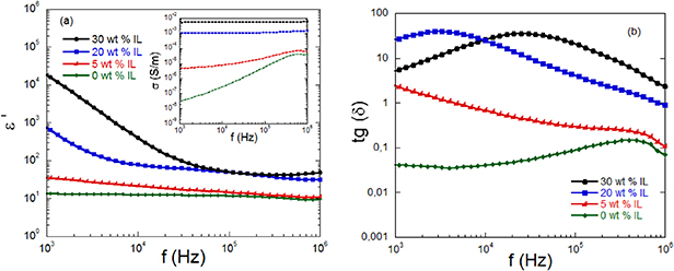
Figure 3. Dielectric constant ' (a) and tg(δ) parameter (b) represented as a function of the frequency for the piezo-ionic PVDF-HFP/[C2mim][NTf2] composites with 0 wt%, 5 wt%, 20 wt% and 30 wt% content of IL. The inset on (a) shows the a.c. conductivity of all the piezo-ionic composites.
Download figure:
Standard image High-resolution imageAs expected, the incorporation of the [C2mim][NTf2] IL results in a huge increase of the real part of the dielectric constant of the PVDF-HFP/[C2mim][NTf2] composite. This increase is more pronounced for the polymer matrix with higher amount of IL. At a frequency of 1 kHz, the dielectric constant of the pure polymer composite increases its value from 10 to 105 when a 30 wt% of IL is incorporated. That increase is caused by the orientation of ions' dipoles and by their accumulation between different regions in the polymer matrix and on the interface between the polymer composite and the gold electrode [38]. However, the increase on the percentage of IL causes a rise of the dielectric losses (tg(δ)) associated to the increase of the imaginary part of dielectric constant parameter ( . That increase is a result of a higher ionic conductivity of the composites when the IL is incorporated in the polymer matrix. This fact can be better observed in the behavior of the a.c. conductivity (inset figure 3(a)), obtained from the dielectric measurements through the equation
  , being
  . The value of the tg(δ) parameter reaches a maximum around 3 kHz and 25 kHz for the composites with 20 and 30 wt% of IL, respectively. These results are a clear evidence of the high mobility of the [C2mim][NTf2] ions in the polymer matrix.
Furthermore, considering that the prepared PVDF-HFP film and PVDF-HFP/[C2mim][NTf2] composites will be subjected to numerous and repeated processes of deformation, their mechanical properties were also analyzed. The stress-strain curves of all the prepared samples are represented in figure 4(a). The results show two main characteristic zones. Firstly, a linear part, which corresponds to the elastic behavior of the sample, and secondly the plastic zone, from the yielding point until the sample rupture.

Figure 4. Stress-strain curves (a) and corresponding Young modulus and yielding point (b) of the piezo-ionic PVDF-HFP/[C2mim][NTf2] composites with 0 wt%, 5 wt%, 20 wt% and 30 wt% content of IL.
Download figure:
Standard image High-resolution imageThe values obtained for the Young's modulus and yielding point are represented in figure 4(b). The observed differences can be attributed to the presence and different percentages of content of the IL. The analysis of the results shows a significant reduction of the Young modulus and of the Yielding point caused by the introduction of the IL in the polymer matrix. A reduction of 19, 51 and 72% for the Young modulus and of 7, 30 and 51% for the Yielding point is observed when 5, 20 and 30 wt% of IL is presented in the composite, respectively. The observed decreasing trends in both cases are related to the known plasticizing effect that the IL generates on the composite [39].
In addition, since the asymmetric deformation in the polymer composite is caused by the magnetostrictive phase, a full magnetic characterization of the Metglas® 2826MB ribbons is also required. Measurements of the magnetic hysteresis loop and magnetostriction of the Metglas® 2826MB ribbon are shown in figures 5(a) and (b), respectively.

Figure 5. Hysteresis loop (a) and magnetostriction and corresponding piezo-magnetic coefficient (b) of the Metglas® 2826MB ribbon.
Download figure:
Standard image High-resolution imageFrom these curves, saturation magnetization and magnetostriction values of 0.88 T and about 11 ppm, respectively, were obtained. From the magnetostriction curve, the corresponding piezo-magnetic coefficient was deduced, with a maximum value of 0.8 ppm Oe−1. Actually, it is well known that this coefficient drives the deformation of the polymer composite phase under the application of a magnetic field [26, 37, 40]. Both in the hysteresis loop and piezo-magnetic coefficient curves, the applied magnetic field required to reach the maximum values is located around 9 Oe.
The induced electric response in the fabricated structures was measured under the simultaneous application of an AC and DC magnetic fields (see figure 6).
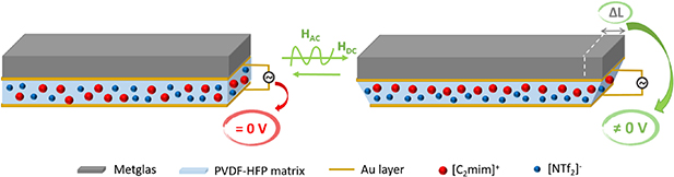
Figure 6. Scheme of the detection of the induced MI response in the fabricated structures. The applied magnetic fields asymmetrically deform the PVDF-HFP/[C2mim][NTf2] polymer composite, causing a separation of anions and cations through piezo-ionic effect, and consequently, inducing an electric response.
Download figure:
Standard image High-resolution imageThe working principle of this induced response is based on the magneto-mechanical-ionic coupling of the laminated composites. Thus, the applied magnetic field deforms the Metglas® 2826MB, transferring the deformation to the piezo-ionic phase. The ions, which were previously distributed uniformly in the polymer matrix, are oriented and displaced in the direction of the expanded region [18, 41, 42], in order to be adapted to the new volumetric conformity. As a result of the different size and mobility between cations and anions of the IL, a charge concentration gradient is observed, which consequently induces a voltage difference (figure 6). From that voltage, the induced MI response across the laminates can be quantified throw the following equation:
where VMI is the induced MI voltage, tpi is the thickness of the piezo-ionic composite and Hac is the amplitude of the applied AC magnetic field, set in 0.5 Oe in all the measurements. Figure 7 shows the MI response of the fabricated laminates as a function of the applied magnetic field, measured at different frequencies. Note that the composite with a 0 wt% of IL does not have any ionic response, so it is not represented in the figures.
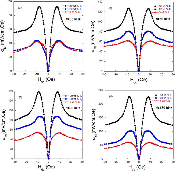
Figure 7. MI coefficients of all the fabricated structures as a function of the applied DC magnetic field, measured at 35 kHz (a), 60 kHz (b), 90 kHz (c) and 150 kHz (d).
Download figure:
Standard image High-resolution imageThe results for all the measured frequencies show a progressive increase of the MI response as the DC magnetic field (Hdc) does. The maximum MI coefficient is obtained at a low applied magnetic field of 9 Oe, value that corresponds to the largest deformation of the Metglas® 2826MB, and decreases at the final stage for higher values of Hdc. Actually, larger deformations cause higher stress gradients, which induces the movement of ions in the direction of expanding regions (see figure 6). The larger mobility of [C2mim] cations in comparison with the [NTf2] anion [42] generates a separation and orientation of charges that leads to the measured electrical output.
In addition, different MI responses are observed as a function of the frequency. Figures 8(a) and (b) represent the evolution of the induced MI response as a function of the frequency of the AC magnetic field and of the ionic liquid content, respectively, for all the fabricated Metglas® 2826MB/PVDF-HFP/[C2mim][NTf2] composites.
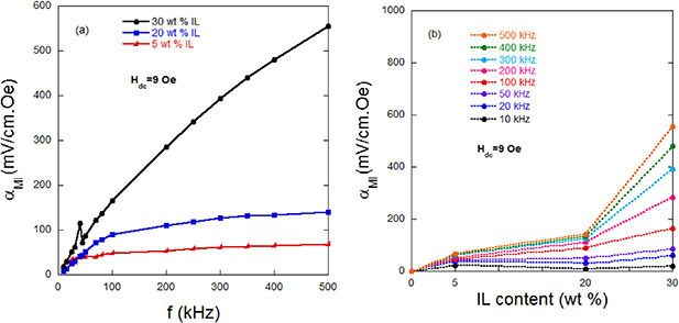
Figure 8. MI coefficient of all the fabricated structures as a function of the frequency (a) and as a function of the percentage of IL content (b), measured at an applied Hdc magnetic field of 9 Oe.
Download figure:
Standard image High-resolution image
As can be appreciated, the MI response increases as the frequency of the applied AC magnetic field does, for all the analyzed cases. Unlike the common magneto-electric laminates [43], these structures do not show a pronounced electromechanical resonance frequency. Actually, the low Young's modulus values of the piezo-ionic composites (between 60 and 220 MPa) can lead to damping effects in mechanically coupled structures [44], which directly affects the quality factor and, consequently, the electromechanical resonance of the laminates [45–47]. Furthermore, the movement of ionic liquids within the polymer matrix is highly dependent from the stretch frequency over a wide range, which has also a significant influence in the ionic response [48]. According to the literature, the most important processes of IL mobility relaxations only occurs at frequencies close to 100 MHz [49]. Thus, below those values, the differences in the mobility between the [NTf2]- anion and [C2mim]+ cation are more prevalent as increasing the frequency, resulting in a more effective separation between them and, as a consequence, into a higher induced MI response.
Since the MI effect in these laminates is based on the IL movement/orientation, this trend will be more pronounced as increasing the IL content. In fact, the more the percentage of IL in the PVDF-HFP matrix, the higher is the quantity of anions and cations separated by the magnetostrictive effect of the Metglas® 2826MB, which is translated into an increase of the induced MI response. However, this behavior is not observed at low frequencies. At those frequencies, the values of MI coefficient among the different samples is not so significant and, at frequencies lower than 35 kHz, it is even higher for samples with lower percentage of IL. This fact can be attributed to the ionic conductivity losses of the samples with 20 wt% of IL when compared with the 5 wt% of IL sample at those frequencies (see figure 3(b)).
Finally, the MI coefficient value for the laminates with 5 and 20 wt% of IL stabilizes at 250 and 400 kHz, respectively, showing values for the MI coupling of 60 and 140 mV cm−1.Oe. On the contrary, the sample fabricated with 30 wt% of IL shows a continuous and accentuated increase of the MI response up the measured frequencies of 500 kHz, reaching a value of 550 mV cm−1.Oe. This trend is expected to continue until frequencies close to 100 MHz, where the slowest and largest relaxation processes of the ionic liquid appear [41, 49]. The MI coefficient obtained values are comparable, and even higher, than others obtained with recent composites based on multiaxial molecular–ionic ferroelectric/magnetostrictive materials [28] or ME composites [50, 51], where values up to 186 mV cm−1.Oe have been reported. Thus, our flexible and low cost developed structures based on non-polarized piezo-ionic/magnetostrictive materials open new perspectives in the development of advanced and functional composites for novel energy generation devices.
4. Conclusions
Novel piezo-ionic/magnetostrictive energy generation structures based on Metglas® 2826MB layers and the PVDF-HFP/[C2mim][NTf2] polymer composites have been fabricated. For the first time, an electric response has been measured in such bi-layer composites, which do not need a piezoelectric phase to show an induced voltage. The results are based on the magneto-mechanical-ionic coupling of the laminated composites. It was demonstrated that the Metglas® 2826MB asymmetrically deforms the piezo-ionic PVDF-HFP/[C2mim][NTf2] composite under the application of a magnetic field. This deformation causes an asymmetric distribution of the ions in the polymer matrix, which generates an induced electric response.
Magneto-ionic responses up to 550 mV cm−1.Oe have been obtained under a low applied magnetic field of 9 Oe for composites with a 30 wt% of IL. The results show in general a progressive increase of the MI response as increasing the percentage of IL of the PVDF-HFP polymer composite and as increasing the frequency of the applied AC magnetic field. The obtained induced values are higher than others previously reported in the literature for the traditional ME composites with polarized piezoelectric phases, making these structures a promising alternative for advanced energy generation systems.
Acknowledgments
A. L. and J. G. would like to thank the financial support from the Basque Government under the ELKARTEK (KK-2018/00099) and Research Groups (IT1245-19) projects. A.C.Lopes thanks to MSCA-IF-2015 (Marie Skłodowska Curie Actions) of the European Union's Horizon 2020 Programme for the received funds under grant agreement n° [701852].