
Abstract
We report here a record 4.6 T trapped field generated by high temperature superconducting (HTS) persistent current loops using a HTS ring structure. By stacking 200 HTS rings into a compact magnet 90 mm in diameter, we performed a field cooling magnetisation at 25 K. The main advantage of the new magnet compared to existing trapped field HTS magnets is that the magnetic field is in the parallel direction to the ab plane of the HTS, leading to higher critical currents in the same magnetic field. Therefore, compact HTS magnets can be developed based on this principle to achieve high magnetic fields. Experimental results show that the final trapped field distribution depends on the ring geometry. We developed a new three dimensional model to simulate the magnetic field distribution within the HTS ring magnet and good agreement between experiments and simulation have been found. The temperature dependency and ramping rate dependency have been studied numerically as potential factors to influence the magnet field. The proposed HTS ring magnet will have promising applications in medical imaging devices, e.g. MRI, as well as electrical machines.
Export citation and abstract BibTeX RIS

Original content from this work may be used under the terms of the Creative Commons Attribution 4.0 licence. Any further distribution of this work must maintain attribution to the author(s) and the title of the work, journal citation and DOI.
Introduction
High temperature superconducting (HTS) permanent magnets have huge potential for providing strong magnetic fields within a compact structure. In a superconducting state, zero resistivity enables the continuous flow of any induced magnetization currents, which can generate a constant magnetic field without connecting to a power supply. In electric machines, superconducting trapped field magnets have already been used [1, 2], applications as loss-less bearings [3–5] and magnetic field generators have also been demonstrated [6]. There are mainly two types of HTS permanent magnets: HTS bulks and HTS stacked tapes. HTS bulks have been studied extensively, and a silver-doped GdBCO bulk with a stainless steel ring as a reinforcement has recently achieved a 17.6 T trapped field [7]. The highest magnetic field achieved by HTS stacked tapes is 17.7 T using a hybrid stack [8]. Although these HTS permanent magnets provide very high magnetic fields, their sizes are limited by manufacturing methods. Using the multi-seed technology, the size of a HTS bulk can be up to 65 mm in diameter [7] and the maximum width of a commercial 2G HTS coated conductor is 46 mm [9]. It is technically challenging to produce HTS permanent magnets larger than 50 mm.
A new ring shape HTS magnet has been proposed to build a HTS permanent magnet [10, 11] with large dimensions. The HTS ring magnet can be made of a HTS coated conductor by splitting the conductor in the middle and opening it up to make a jointless persistent current loop. The HTS rings can be stacked to form a compact magnet and it can be flexible in size by choosing different lengths for splitting. The ring magnet is a potentially more resilient device compared to HTS wound magnets as each loop is independent in carrying the persistent current and any individual loop fault or critical current weak point will not affect the performance of the whole magnet. The full penetration field depends on the critical current density of the superconductor and the geometry of the sample [12]. The HTS ring magnet has relatively higher critical current density Jc comparred to HTS bulks and stacks at the same magnetic field. As shown in figure 1, during magnetisation, the external magnetic field Bz is perpendicular to the a-b plane of the REBCO crystals for both HTS bulks and stacks, leading to a dramatic reduction in Jc. The Lorentz force generated by Bz over the induced current helps the individual flux vortex to conquer the pinning forces in the a-b plane. The higher the Bz, the easier the flux vortex can conquer the pinning forces, therefore the lower the critical current becomes. In contrast, for HTS ring magnets, the ab plane and the induced current is parallel to Bz, resulting in zero Lorentz force. So its Jc will be much less affected by Bz, resulting in higher Jc. As shown in figure 1, at 25 K and 8 T, the Jc of 2G HTS with advanced pinning in the parallel field is roughly four times the Jc in the perpendicular field (indicated in the blue circles). In other words, four times less HTS materials will be required to take the same amount of current at 8 T for the HTS ring magnet, in comparison to the HTS bulks and stacks. Also the operational temperature of the magnet affects the critical current and the generated magnetic field. As shown in figure 1, the lower the temperature, the higher the critical current is when subjected to an external magnetic field.
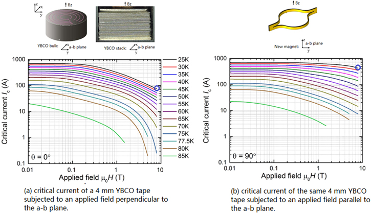
Figure 1. The critical current comparison between HTS bulk/stack and HTS ring magnet showing that at 8 T @25 K, HTS ring has five times higher critical current than HTS bulk/stack. The critical current data is reproduced from the detailed measurements of a 2G HTS YBCO wire at the Robinson Research Institute of Victoria University of Wellington.
Download figure:
Standard image High-resolution imageA feasibility study for HTS rings at low magnetic fields has been reported [10]. Jie Sheng et al [13] studied the relationship between the trapped field and the ring geometry, as well as the demagnetisation subjected to a cross AC field. Several persistent current HTS coils have been made using YBCO tapes and field-cooling was performed for the purpose of trapped fields [14, 15]. The relaxation rate of current and external magnetic fields have been experimentally validated [16]. However, there is no report for using HTS ring magnets to generate high magnetic fields. This paper reports the highest trapped field achieved in HTS ring magnets using field cooling magnetisation.
Sample preparing
A HTS ring magnet is made from a YBCO coated conductor (Superpower M4 AP tape with 20 um copper stabilizer). Each sample conductor is 88 mm in length. Laser cutting was used to cut the tape in the center for 72 mm and each 8 mm tape was left intact on both ends as shown in figure 2(a). Figure 2(b) shows the critical current of one HTS tape after splitting. The critical current of a tape measured by the manufacturer was 520 A at 77 K. After splitting, the critical current reduces to 490 A.
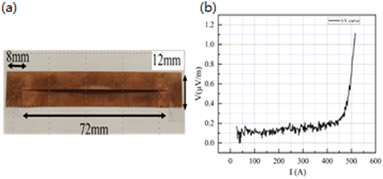
Figure 2. (a) Schematic of one splitted tape. (b) V-I curve of one splitted tape during critical current measurement at 77 K.
Download figure:
Standard image High-resolution image100 HTS rings are stacked together to form a ring stack. The former inside the HTS ring is 20 mm in diameter. A double-layered ring stack is used in this experiment as shown in figures 3(a) and (b), by placing two ring stacks together. Due to the asymmetric geometry, the closed side of the magnet sees two HTS layers closely stacked together while the opened side of the magnet sees a 12 mm gap between two HTS layers as shown in figures 3(a) and (b). This geometry gives a freedom in the selection of the inner diameter of the magnet. In addition, each ring works independently so any local degradation will not degrade the performance of whole magnet. The stacked ring magnet was placed in a brass holder and impregnated with paraffin wax mixed with aluminium nitride. Figure 3(c) shows the sample holder after impregnation. The outer diameter of the magnet holder is 90 mm. Three hall sensors are positioned respectively in the centre (H3), 4.5 mm from the center towards the closed side (H4) and 4.5 mm from the center towards the opened side (H2), as shown in figure 3(d). These sensors are mounted on a double sided PCB board: H2 and H4 are on same side and H3 is on the opposite side.
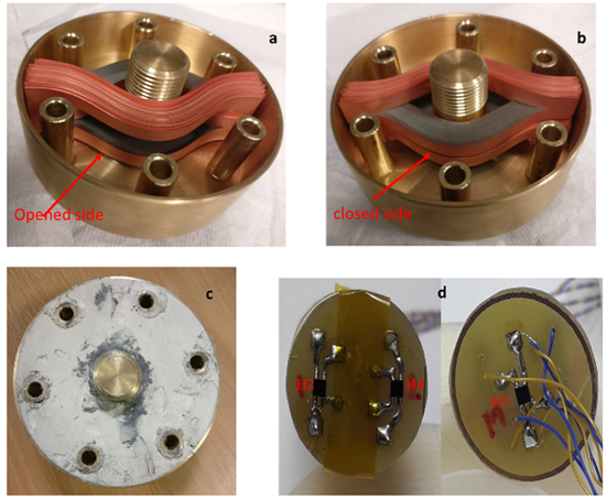
Figure 3. (a) and (b) show the double layered ring magnet sitting in a brass holder. The opened side and the closed side of the ring are indicated respectively. (c) after paraffin impregnation. (d) Hall sensors mounted on double sided PCB board.
Download figure:
Standard image High-resolution imageMagnetisation results
The ring magnet sample was magnetised using the wide bore magnet at the University of Cambridge. Figure 4 shows the experimental setup. The sample was attached to a cold plate connected to a two stage cooler. Helium was injected to the sample chamber through a needle valve. The cold head controls the temperature of the sample with a heater attached to it and the helium gas acts as the medium of conduction. Field cooling (FC) was performed by using a low temperature superconducting magnet to provide a background magnetic field. The external field was homogenous in the region where the sample was placed. Firstly, the magnet sample was cooled to 110 K. Secondly, the applied field was ramped to 5 T and the sample was cooled to 25 K in the presence of the constant 5 T. The 5 T field was then ramped down slowly to zero to minimise heat generated in the sample. A heater attached to the cold plate monitors the temperature of the sample. The temperature of the top plate is almost constant during the magnetisation process, as shown in figure 5. During the experiment, the heat generated within the magnet is well exchanged via the paraffin wax mixture with the brass holder. The temperature is considered to be constant throughout the experiment. As the thermometer was not in direct contact with the sample (thermally connected by a brass mount and paraffin wax) the warming would be higher within the sample.

Figure 4. The experimental setup configuration.
Download figure:
Standard image High-resolution image
Figure 5. Temperature profile during experiment at 25 K.
Download figure:
Standard image High-resolution imageDuring and after the magnetisation, the magnetic field from H2-H4 and the applied field were recorded. The actual trapped field generated by the induced persistent currents in the HTS ring magnet is the measured H2-H4 field minus the applied field, as shown in solid lines in figure 6. The star shows the trapped field when the external field is ramped down to zero. A peak trapped field of 4.60 T is recorded from hall sensor H4 which is near to the closed side of the magnet. The central hall sensor H3 records 4.1 T while the hall sensor H2 near the open side of the magnet recorded 3.8 T. This variation in the trapped field is due to the asymmetric geometry of the ring magnet. When the applied field was decreasing, persistent current loops in the HTS rings were induced, resisting the change of total flux within the magnet. The induced current in the closed side generates a higher internal magnetic field compared to the opened side, since the conductors are closer to the hall sensor H4.
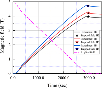
Figure 6. Trapped fields at 25 K with the applied field for FC. The highest trapped of 4.60 T at 4.5 mm right from middle. Btr–Bext for the experimental trapped field results.
Download figure:
Standard image High-resolution imageAll magnetized superconductors experienced flux creep, which is due to disturbances in flux vortex and HTSs experience higher flux creep rates [17, 18]. This flux creep causes the trapped field of the superconducting magnet to decrease. The flux creep rate of the HTS ring magnet was measured for 16.5 h as shown in figure 7. All three hall sensor measurements show the same decay rate. In the beginning the trapped field reduces with a faster rate and later it became stable and the decay rate reduced. The time dependence of the decay is logarithmic and is calculated as:
where t0 is an arbitrary unit of time in seconds. The fit to the normalised data gives the values a = 1.08 and b = −0.02. The normalized flux creep graph shows that the decay rate of all the values is the same so a generalized expression was obtained. The values of B0 are 4.60 T, 4.19 T and 3.8 T. To understand how the flux creep will impact the trapped magnetic field over a period of time, it is standard practice to calculate how much time it will take to decay a set percentage [16]. It is calculated that it will take 1.76 × 10⁴ s to decay by 1% and after that, the decaying time increased to 3.06 × 10⁴ s for the same period.

Figure 7. Normalized flux creep for different positions within the ring magnet and noted for 16.5 h. B0 is the final trapped field as marked by stars in figure 6.
Download figure:
Standard image High-resolution imageModelling and physics discussion
To help understand the physics of HTS ring magnets, a three-dimensional finite element modelling was performed using the homogenised H formulation [19]. The 3D governing equation can be represented by the general form [20]:

where H = [Hx, Hy, Hz]T, ρ = [ρx, ρy, ρz]T is the resistivity. For HTS domains, ρ is governed by the E-J power law [21]. The magnetic field dependence of critical current density Jc(B) is considered in the model using direct interpolation of measurements of Jc(B) at 25 K.
The HTS ring magnet has 200 rings with a 3D asymmetric geometry, it is not possible to model all the rings in detail due to the high aspect ratio of 2G HTS. The previous established H formulation homogenisation [19] takes two assumptions into account; first the thickness of HTS has been artificially increased from 1 μm to 74 μm, which is the total thickness of the HTS tape; secondly, it is assumed that every ten HTS rings has the same critical current penetration depth. Therefore, every ten HTS rings is homogenised as a single HTS domain, which means the ten HTS rings have the same current distribution. One layer of HTS rings with 100 tapes is therefore represented by ten HTS domains, separated by nine air domains. There is an air domain between each two layers of HTS domains.
Figure 8 shows the comparison between experiment and modelling results. The model employs a much faster ramping current of external magnetic fields due to calculation time limits so figure 8 is shown in a normalised time plot. Solid lines are for experiment results and the dotted lines are for the modelling results. The difference between the modelling result and the experimental result is less than 7%. Figure 9 illustrates the current distributions in the HTS ring during an FC cycle, corresponding to five different time steps. The current distributions in the rings are not uniform, affected by the critical current density distribution and the magnetic field distribution. The current is induced simultaneously from the innermost and the outermost HTS domains when the magnetisation starts. When the applied field is further reduced, more current is induced in the middle HTS domains and the penetration depth of each HTS domain increases.
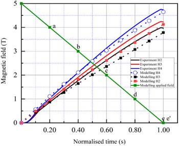
Figure 8. Simulation results. Points (a)–(e) and (e') show the time steps for normalised current distribution shown in figure 9. The calculation uses a 10 s ramping rate for the magnetic field.
Download figure:
Standard image High-resolution image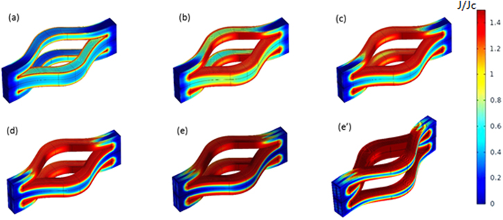
Figure 9. The distribution of the normalised current density (J/Jc ) in the ring magnet during the ramping down process. (a) applied field = 4 T, (b) applied field = 3 T, (c) applied field = 2 T, (d) applied field = 1 T, (e) applied field = 0 T for the closed side and (e') applied field = 0 T for the opened side.
Download figure:
Standard image High-resolution imageFigure 10 shows the current distribution in individual HTS domains and the total current induced in the rings during the FC process. Ring 1–10 indicates the innermost domain while ring 91–100 indicates the outermost domain. When the applied field reduced, the inner and outer domains start to induce persistent current loops to compensate the field reduction from the applied field. The current in the inner and outer domain reaches its peak value at 20% of applied field reduction. This saturation of inner and outer rings currents leads to weakened shielding effects for the middle domains and forces the current to be induced in the middle rings. This process continues until all the domains saturate. The middle domains with rings 41–60 have the highest current flowing in them after magnetisation. The changing magnetic field decreases the critical current of the outer and inner rings, so the maximum induced current value is also limited by the reduction in critical current. According to figures 7(e) and (e'), the outermost domain is not fully penetrated even when the magnetisation is finished. This is because it has the highest critical current density.

Figure 10. Calculated induced currents in 10 HTS domains during the 5T FC process.
Download figure:
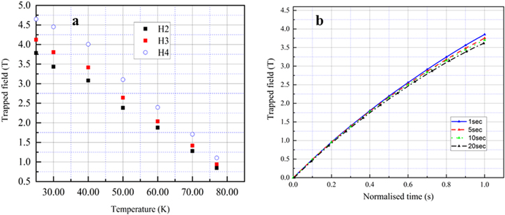
Standard image High-resolution imageThe 3D model was then used to study the impact of operational temperatures and the ramping rate of external magnetic field. Figure 11(a) shows the temperature versus the peak magnetic field generated by the HTS ring magnet sample at three different hall sensor positions. The temperature dependency of the critical currents at 25 K used in the model is in figure 1. The higher the temperature, the lower the trapped field, due to the reduction of critical currents.
Figure 11. (a) Temperature versus peak trapped field at H2,H3 and H4. (b) Trapped field comparison for three different ramping rates.
Download figure:
Standard image High-resolution image
When a superconducting loop is placed in a changing external magnetic field and the temperature of the sample is below its critical temperature, it induces a current to compensate the change of total magnetic flux inside the ring. Figure 11(b) shows the magnetic field profile at the center of the ring magnet subjected to different ramping rates of external magnetic field. Due to the different time scales in different damping rates, figure 11(b) is plotted using a normalised time scale. To understand how the ramping rate affects the trapped field, according to Faraday's Law [22], we have:

here L is the inductance, φ is the total flux, i(t) is the induced current, V0 = E0l, E0 = 1 μV cm−1 as the criterion for measuring Ic, l is the length of the ring, and n is the EJ power law index. When the changing rate is very slow as it is in the FC experiment, the heat dissipation inside the sample holder is small, so the temperature inside the ring remains constant, as well as the Ic of the HTS rings. Due to the existence of the E-I power law term in equation (3), the changing rate of the induced current is not directly proportional to the changing rate of external flux. When the ramping rate of magnetic field is increased, the changing rate of i(t) can be higher. But when i(t) is higher than Ic, the E-J power law term steps in and it limits the peak i(t) value. The final total currents flowing in the ring are dominated by the in-field critical current of the rings. As shown in figure 11(b), there are only slight differences in the final trapped field using different ramping rates: the lower the ramping rate, the lower the trapped field. This is because when the ramping rate is lower, the induced current inside the HTS ring experiences a longer period of flux creep during magnetisation.
In conclusion, a trapped field of 4.60 T was recorded using the FC magnetization method for a double-stacked HTS ring magnet. The HTS ring magnet can be flexible in size by choosing different slit lengths, and several ring magnets can be stacked together to make a longer magnet. Good agreement between the experiment and simulation have been found. The magnetisation mechanism was explained by simulating the current distribution during different time steps of the magnetisation. The magnet technology is promising for making HTS permanent magnets with large sizes. The magnetic field distribution within the magnet is asymmetrical due to the unique geometry of double-stacked HTS ring magnets. New stacking methods need to be investigated in order to improve the magnetic field homogenisation for practical applications.
Acknowledgments
This work was funded by the UK Royal Society Research Grant (RSG\R1\180032), the National Key Research and Development Program of China (2017YFE0123400). The authors would like to acknowledge the Henry Royce Institute (Equipment grant ref. EP/P024947/1) for financial support. The authors would like to thank Anthony Dennis for his technical support during testing.