

Abstract
Superconductors are key materials for shielding quasi-static magnetic fields. In this work, we investigated the shielding properties of an MgB2 cup-shaped shield with small aspect-ratio of height/outer radius. Shape and aspect-ratio were chosen in order to address practical requirements of both high shielding factors (SFs) and space-saving solutions. To obtain large critical current densities (Jc), which are crucial for achieving high magnetic-mitigation performance, a high-purity starting MgB2 powder was selected. Then, processing of the starting MgB2 powder into high density bulks was performed by spark plasma sintering. The as-obtained material is fully machinable and was shaped into a cup-shield. Assessment of the material by scaling of the pinning force showed a non-trivial pinning behaviour. The MgB2 powder selection was decisive in enlarging the range of external fields where efficient shielding occurs. The shield's properties were measured in both axial- and transverse-field configurations using Hall probes. Despite a height/outer radius aspect ratio of 2.2, shielding factors higher than 104 at T = 20 K up to a threshold field of 1.8 T were measured in axial-field geometry at a distance of 1 mm from the closed extremity of the cup, while SFs > 102 occurred in the inner half of the cup. As expected, this threshold field decreased with increased temperature, but SFs still exceeding the above mentioned values were found up to 0.35 T at 35 K. The shield's shape limits the SF values achievable in transverse-field configuration. Nevertheless, the in-field Jc of the sample supported SFs over 40 at T = 20 K up to a field of 0.8 T, 1 mm away from the cup closure.
Export citation and abstract BibTeX RIS
1. Introduction
Owing to their ability to expel magnetic flux, superconducting materials have been demonstrated to be promising candidates for the fabrication of efficient low-frequency passive magnetic shields. In particular, their use is crucial in several kinds of applications, for instance when shielding magnetic flux density over 1 T [1–3] or very low magnetic field background [4–6] is required.
Shielding properties of superconducting bulks with cylindrical and planar geometries and made from different materials have successfully been investigated [7–11]. Moreover, improvements in the shielding performance have been found by superimposing superconducting bulk and tapes [12] or taking advantage of the combined use of superconducting and ferromagnetic materials [13–15].
In this context, MgB2 bulk shields have shown great potential [16–18]. Indeed, MgB2 long coherence length is suitable for supporting the fabrication of large untextured polycrystalline samples, because the flow of high critical current density, Jc, across clean grain-boundaries is not prevented by weak-link effects, even when two pellets are joined [19]. This has fostered the development of processing techniques able to produce and assemble dense MgB2 bulk samples with almost isotropic and homogeneous Jc, into complex geometries [17, 20–23]. The starting elements are cheap, non-toxic and do not include rare-earths, and the small weight density of this superconductor makes it attractive for portable applications such as space ones [24]. Besides this, the typical operating temperatures (20–30 K) of this compound can be easily reached using closed-cycle cryocoolers or liquid H2.
All the above mentioned characteristics make MgB2 able to face the major challenges in the field of magnetic shield fabrication [25]. In our previous paper [18], we reported on a novel fabrication technique that, starting from spark plasma sintering (SPS) of MgB2 and hexagonal BN powders, produces fully machinable MgB2 bulks, which can be geometrized in order to meet specific shape requirements. The first shielding experiment carried out on a hollow cylinder, fabricated with this technique, showed promising values of the shielding factor (SF), especially considering the small aspect ratio of height/radius of the sample (1.75). In the same paper, we also demonstrated by computation how the addition of a cap (disk) on one of the tube's apertures would lead to SFs over 104 at T = 25 K in axial applied fields up to μ0Happl = 1.0 T.
Based on these calculation results and in order to address this topic experimentally, in this work we applied the same fabrication process to produce a cup-shaped shield. With the aim of obtaining a significant improvement in the shielding factor independently from the direction of the external field, the shield was manufactured by suitably shaping a single bulk cylinder, so as to guarantee a superconducting joint between the tube and its cap. Indeed, it was demonstrated that a cap addition provides a noteworthy increase of the tube's shielding ability even in transverse-field configuration, only if cap and tube are 'fused' together [26], as it happens when they are fabricated in the same process.
In addition, since high shielding performance also requires large Jc values [25, 26], we worked to improve the effective current carrying cross-sectional area by an accurate selection of the starting MgB2 powder.
As in our previous works [15, 18], the shielding vessel had a small aspect ratio of height/outer radius. Indeed, this geometry can be useful to address magnetic mitigation solutions in situations where the space occupied by the shield and its mass must be minimized (e.g. space applications [27, 28]). Furthermore, the choice of a small aspect ratio is necessary when the shield radius is so large that, in practice, its height cannot be much longer than the radius [29].
The paper is organized as follows. In section 2, we briefly recall the details of the sample fabrication process and describe the experimental procedures used for their characterization. The experimental results concerning x-ray diffraction analysis, the critical current density and pinning force evaluation and the shielding measurements are reported and discussed in section 3. The main findings are summarized in section 4.
2. Experimental details
2.1. MgB2 fabrication process
MgB2 commercial powder was mixed with hexagonal BN (BNh, henceforth). The mixture was loaded into a graphite die with 20 mm inner diameter and processed by spark plasma sintering at 1150 °C for a dwell time of 8 min. The maximum pressure applied on the sample during sintering was 95 MPa. More details of the fabrication process are reported in [30]. The as-prepared cylinder (25 mm in height) was fully machinable [31] and, at first, it was partially bored by using drill bits and then it was refined in the final cup-shape by means of a lathe machine. Two pictures of the final product (simply named cup, henceforth) are shown in figure 1. Its geometrical parameters are specified in the figure caption and its aspect ratio, defined as the ratio of the external height over the outer radius is 2.2.
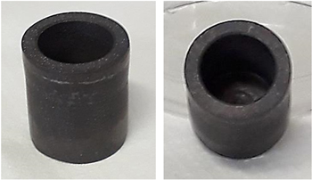
Figure 1. MgB2 cup fabricated by spark plasma sintering, drilling and final refining on a lathe machine. Geometrical parameters: outer radius, Ro = 10.15 mm, inner radius, Ri = 7.0 mm, external height, he = 22.5 mm, internal depth, di = 18.3 mm.
Download figure:
Standard image High-resolution image2.2. Measurements details
The structural analysis of the sample was carried out with a Bruker-AXS D8 ADVANCE diffractometer (CuKα1 radiation, λ = 1.5406 Å). Phase concentration, crystallite size and lattice parameters of MgB2 were extracted from Rietveld analysis. The bulk density of the full cylinder before shaping into cup was determined by the Archimedes method using toluene as weighting medium.
Magnetic measurements were performed with a physical properties measurement system (PPMS 14 T, Quantum Design, US) on a sample with dimensions 1.5 cm × 1.5 cm × 0.5 cm cut from residual parts obtained in the shaping process of the as-spark plasma sintered (as-SPSed) cylinder. Transition temperature, Tc, is defined as the onset temperature of the superconducting transition in the curve of magnetisation versus temperature, M(T), measured applying a magnetic field μ0Happl = 10 mT after zero-field-cooling. From magnetisation loops carried out at different temperatures the critical current density, Jc(H), curves were extracted by using the Bean model [32]. The irreversibility field, Hirr, obtained from the same measurements, was defined as the field at which Jc is 102 A cm−2.
For the shielding experiment, the cup was placed in tight thermal contact with the second stage of a cryogen-free cryocooler. More details on the experimental setup are reported in [18]. First, the cup was cooled in zero field down to the working temperature and then a homogenous dc field was applied either parallel or perpendicular to the sample's axis with an average rate of 1 × 10⁻⁴ T s−1. The local magnetic flux density was measured by means of five cryogenic Ga–As Hall probes [33] located along the cup's axis as sketched in figure 2. The probes were always oriented to measure the component of the magnetic induction parallel to the applied field (i.e. Bz).
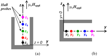
Figure 2. Schematic drawing of the Hall probe arrangements for the axial- (a) and transverse- (b) magnetic field measurements. In the axial-field configuration, assuming z = 0 the coordinate of the closed extremity, the Hall probes were positioned at z1 = 1 mm, z2 = 5.0 mm, z3 = 9.2 mm (shield's centre), z4 = 13.7 mm and z5 = 18.3 mm (shield's open extremity). Likewise, in the transverse-field configuration, assuming y = 0 the coordinate of the closed extremity, the Hall probes were placed at y1 = 1 mm, y2 = 4.6 mm, y3 = 9.2 mm (shield's centre), y4 = 13.7 mm and y5 = 18.3 mm (shield's open extremity). The external field was always applied parallel to z axis and the Hall probes were always oriented to measure Bz.
Download figure:
Standard image High-resolution image3. Results and discussion
3.1. Structural analysis
Figure 3 compares the x-ray diffraction (XRD) patterns of the starting MgB2 raw powder and corresponding spark-plasma sintered sample added with BNh. In the starting powder, besides the MgB2 main phase, impurity phases of MgO and Mg were present. Their weight concentration is summarized in table 1, together with the average crystallite size. It is worth mentioning that the MgB2 phase concentration in the raw powder and in the SPSed bulk was about 10% higher than in the case of the cylinder sample investigated in [18]. We also note that the ratio among secondary phases in the raw MgB2 powder is much different in this work compared to the previous one [18]: for MgO it is 1.8 against 4.6 wt%, for MgB4 0 against 7.1 wt%, and for Mg 1.2 against 0.3 wt%, respectively. The lower amount of non-superconducting phases, such as MgO, in the sample from this work is expected to positively affect Jc since the presence of impurity phases reduces the supercurrent effective cross-section [34].

Figure 3. X-ray diffraction patterns of MgB2 raw powder (a) and (MgB2 + 10%wt BNh) sintered bulk cylinder (b).
Download figure:
Standard image High-resolution imageTable 1. Lattice parameters, phase content (without considering the amount of BNh) and average crystallite size of the MgB2 raw powder and of the final bulk product.
| Lattice parameters [Å] | Phase concentration [wt%] | Average crystallite size [nm] | ||||||||
|---|---|---|---|---|---|---|---|---|---|---|
| a | c | MgB2 | MgB4 | MgO | Mg | MgB2 | MgB4 | MgO | Mg | |
| MgB2 raw powder | 3.087 | 3.522 | 97 | — | 1.8 | 1.2 | 113 ± 10 | --- | 45 ± 6 | 51 ± 4 |
| MgB2 bulk cylinder | 3.084 | 3.525 | 73 | 18 | 9 | — | 138 ± 3 | 200 ± 20 | 41 ± 1 | — |
The density of the final bulk sample was 2.50 g cm−3. Since the theoretical density of the composite is 2.62 g cm−3, as determined by considering the wt% of the component phases and their theoretical densities [30], it results a relative density of ∼95%, indicating a good grain packing.
3.2. Critical temperature, critical current densities and pinning forces
The normalised magnetisation of the sintered bulk displays a very sharp superconducting transition, as reported in the inset of figure 4. The transition temperature is 38.9 K. This high value of Tc indicates the lack of chemical reactions between MgB2 and BNh powders [35]. Moreover, we argue that possible MgB2 contamination with carbon from the graphite mould system during SPS processing can also be neglected since C entering on B sites strongly reduces Tc [36].

Figure 4. Main panel: Jc dependence on the applied magnetic field at different temperatures (open symbols: Jc values extracted from the hysteresis loops carried out on a small sample—see section 3.2; solid symbols: Jc values calculated from Bz versus μ0Happl cycles measured by the Hall probe located at position z5 along the cup's axis—see section 3.3.1). Inset: normalised magnetisation of the bulk product as a function of temperature.
Download figure:
Standard image High-resolution imageThe main frame of figure 4 shows the critical current density calculated from magnetic hysteresis loops as a function of the external field and for temperatures ranging from 5 to 35 K. The self-field Jc0 (figure 5(a)) reaches values of 4.0 × 10⁵ and 2.7 × 10⁵ A cm−2 at T = 5 and 20 K, respectively, which are comparable or slightly higher than Jc measured on undoped MgB2 samples used for practical applications as bulk magnets [37, 38]. Moreover, both Jc0 and in-field Jc are higher than for machinable SPSed sample from [18], demonstrating the high influence of the raw MgB2 powder on samples quality and performance. However, these values are lower than the highest ones for non-machinable optimally-doped SPS MgB2 [39]. Indeed, the price to pay to obtain a fully machinable material, which is crucial for applications, is to have slightly lower material's performance in terms of critical current density and correlated parameters, such as the quality product ( —see figure 5(b)) and the maximum pinning force, Fp,max (figure 5(c), being Fp calculated as
  ). Conversely, the machinable sample from this work retained a high irreversibility field (figure 5(d)). Considering this observation, it is of much interest to further investigate the pinning mechanism details.

Figure 5. The dependencies on temperature of: (a) self-field critical current density Jc0, (b) irreversibility field μ0Hirr, (c) quality product ( ), and (d) maximum pinning force Fp,max. Dashed lines are a guide to the eye.
Download figure:
Standard image High-resolution imageTo this aim, the pinning forces versus applied field curves were normalised following the universal pinning force scaling procedure reported in [40, 41]. Then, the experimental data was fitted by the law:

where 
 A, p and q are fitting parameters, and in particular, p, and q values are correlated to vortex pinning mechanisms [41]. Moreover, considering percolation aspects and defining
  the pinning-force related parameter
  introduced by Eisterer [42] was also taken into account. Theoretical values for grain-boundary pinning (GBP) (i.e. surface pinning) are h0 = 0.2, p = 0.5, q = 2, kn = 0.34 and for point pinning (PP) they are h0 = 0.33, p = 1, q = 2, kn = 0.47 [41, 42].
The parameters h0, and kn are plotted as a function of temperature in figure 6(a). They show an increase with temperature and this suggests a strengthening of the point pinning at high temperatures, considering that the values kn (as well as h0 at high temperatures) are close to their respective theoretical values for PP mechanism (h0 = 0.33 and kn = 0.47). This is the typical case for MgB2 pristine and BN added samples fabricated by SPS [39].

Figure 6. (a) Pinning force parameters h0 and kn versus temperature; (b) scaling of the pinning force at 5 K in the entire field range (continuous red line is the fit for the indicated A, p, q parameters); (c) derivative of the pinning force (see text) at 5 K indicating two linear domains with linear fit parameters p1, −q1 and p2, −q2, respectively; (d) p1, q1, p2, q2 and μ0Hcross behaviour with temperature. Dashed lines in figures (a) and (d) are a guide to the eye.
Download figure:
Standard image High-resolution imageHowever, a deeper investigation in the framework of Dew–Hugues model [41] seems to indicate that different mechanisms are simultaneously active. For investigated temperatures within 5–30 K range, fits by equation (1) yielded fitting parameters that do not agree with the theory (figures 6(b), (d)). In addition, by plotting the derivative  versus
  two linear dependencies were obtained (figure 6(c)). The line intercept with y-axis and the opposite of the slope for each linear domain are the pinning force parameters p1, q1 and p2, q2, respectively. By defining
  the crossover coordinate between the two regions, xcross, corresponds to the crossover scaled field
  The corresponding crossover field is
  Parameters p1, q1, p2, q2, and μ0Hcross are given as a function of temperature in figure 6(d). Parameters p1, p2, and q2 almost do not depend on temperature. The exception is q1 that is decreasing when temperature increases. A decrease from 2.8 to 0.8 T is also visible for μ0Hcross. The values of p1 (∼1.7) and q1 (4.6–5.9) and variation of the latter parameter with temperature are approximately similar to those reported in [43] for the composite non-machinable samples with starting compositions ((MgB2)0.99(Tex(HoO1.5)y)0.01), x/y = 0.31/0.69, 0.25/0.75. On the other hand, the values of p2 (∼−0.6) and q2 (∼2.1) and the variation of these parameters with temperature is very different than for the indicated samples: the dependencies p2(T) and q2(T) for MgB2 samples co-added with Ho2O3 and Te show a higher degree of complexity and, hence, of pinning behaviour. The physical meaning for the obtained negative values of p2 from this work remains unclear and further research is needed.
3.3. Magnetic shielding measurements
The shielding properties of the cup were investigated in the temperature range from 20 to 35 K. We explored the magnetic mitigation performance of the manufact in both axial- and transverse-field configuration in order to attain more meaningful information on its competitiveness in practical applications where generic field orientations are likely.
The shielding efficiency was estimated using two parameters: the shielding factor (SF), calculated as the ratio between the applied magnetic field and the local magnetic induction measured by the Hall probes, μ0Happl/Bz, and an applied field threshold, μ0Happl,lim, above which the shielding factor drops below a given value.
3.3.1. Magnetic shielding in axial-field configuration
The main frame of figure 7 provides the shielding factors evaluated at T = 30 K along the cup's axis as a function of the applied field, μ0Happl, in axial-field configuration. Despite the aspect ratio of only 2.2, which makes the flux penetration from the cup's edge not negligible, SFs exceeding 104 and 102 were found 1 mm far from the closed extremity (position z1) and in correspondence of the cup's centre (position z3), respectively, up to μ0Happl = 1.0 T. Above this field, the shielding factor sharply decreases due to a flux jump occurrence [44, 45] (figure 7, inset).
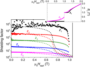
Figure 7. Shielding factors (symbols) measured by the five Hall probes placed along the cup's axis at T = 30 K and as a function of the applied field. The dashed lines represent the shielding factors computed in correspondence of the Hall probe positions, assuming the Jc(B) dependence obtained at T = 30 K in [18] (see text). In the inset, the magnetic induction curves measured by the Hall probes located at positions z1 and z5 are plotted. At μ0Happl = 1 T a flux-jump phenomenon clearly occurred. Measurements and computations were performed in the axial-field configuration.
Download figure:
Standard image High-resolution imageAs mentioned above, we defined a threshold field, μ0Happl,lim∣∣, as the applied field above which the shielding factor drops below a reference value, that must be different in different positions since SFs span over orders of magnitude (see figure 7). We chose SF = 104 for position z1, 103 for position z2, and 102 for position z3. As expected, μ0Happl,lim∣∣ depends on temperature, as summarized in figure 8. Remarkably, at 20 K, SF > 102 up to μ0Happl = 1.8 T were achieved in half the inner volume of the shield (figure 8(c)). In the same range of applied fields, the SF increases over 104 moving towards the closed extremity (figure 8(a)). A further shift of μ0Happl,lim∣∣ to higher applied field values is expected by increasing the lateral wall thickness, reducing the inner radius of the cup. In comparison, a similar SF was found at 20 K for a YBa2Cu3O7 cup with comparable aspect ratio and lateral wall thickness, but only up to μ0Happl,lim∣∣ ∼ 1 T [10].

Figure 8. Temperature dependence of the threshold applied fields, μ0Happl,lim∣∣, above which the shielding factor drops below 104 (for position z1, figure (a)), 103 (for position z2, figure (b)) and 102 (for position z3, figure (c)). Measurements were performed in the axial-field configuration and the dashed lines are a guide to the eye.
Download figure:
Standard image High-resolution imageThen, in order to investigate how the Jc improvement with respect to previous samples [18] affects the shielding properties of the cup, we compared the measured SFs with those expected by assuming the same Jc(B) dependence found in [18]. To this aim, we applied the numerical modelling procedure described in [18] using a cup layout with the same sizes as that characterized experimentally in this work.
As can be seen in figure 7, by assuming in SF calculation ![${J}_{c}\left(B\right)={J}_{c,0}\,\exp \left[-{\left(\tfrac{B}{{B}_{0}}\right)}^{\gamma }\right],$](https://content.cld.iop.org/journals/0953-2048/33/4/044018/revision2/sustab7846ieqn12.gif) where Jc,0 = 3.0 × 10⁴ A cm−2, B0 = 0.83 T and γ = 2.52, i.e. the parameter values obtained in [18] at 30 K, a good agreement between experimental and computed curves is achieved only at low applied fields, where the shielding performance mainly depends on the sample geometry. This is supported also by the evidence that in this field range the SF dependence on the distance from the closed extremity of the shield can also be described by the analytical expression calculated by Claycomb et al [46, 47] for the axial field attenuation by a superconducting tube in Meissner state closed by an end cap. Following [46, 47] the expression
where Jc,0 = 3.0 × 10⁴ A cm−2, B0 = 0.83 T and γ = 2.52, i.e. the parameter values obtained in [18] at 30 K, a good agreement between experimental and computed curves is achieved only at low applied fields, where the shielding performance mainly depends on the sample geometry. This is supported also by the evidence that in this field range the SF dependence on the distance from the closed extremity of the shield can also be described by the analytical expression calculated by Claycomb et al [46, 47] for the axial field attenuation by a superconducting tube in Meissner state closed by an end cap. Following [46, 47] the expression

is predicted, being Ri the inner radius of the tube and z the distance from the center of the end cap. Focusing on z2, z3 and z4 positions (experimental data at z1 position are too scattered), we obtained  = 10.0,
  = 11.7 and
  = 119, in satisfactory agreement to the corresponding experimental ratios: 9.5, 10.0 and 94, respectively.
At higher fields, where the field-dependence of Jc comes into play, this analytical approach does not fit any more and the calculated curves in figure 7 clearly drop faster than the experimental ones. Considering the SF threshold values reported in figure 8, this means that the improvement of Jc(B) raised μ0Happl,lim∣∣ of more than 0.3 T.
Finally, we checked if the critical current density measured on a small sample and reported in figure 4 (open symbols) can be considered representative of the actual current flowing in the whole cup. To address this topic, we measured again the magnetic induction at T = 30 and 35 K by the Hall probes positioned along the cup's axis. To minimize the flux jump occurrence, we furtherly decreased the ramp rate of the applied field down to 5 × 10⁻⁵ T s−1. Then, we calculated Jc from the Bz versus μ0Happl cycle measured by the Hall probe located at position z5 (i.e. in correspondence to the cup's open extremity) as proposed by Bartolomé et al for finite superconducting rings [48]:

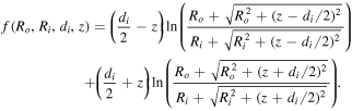
where  is the induction cycle width measured at a given applied field in the axial-field configuration and the function f provides the dependency of Jc on the geometry of the system:
In our case Ro and Ri are the outer and inner radii of the cup, respectively, di the cup internal depth and z the distance from the cup's centre (i.e. z = z3). We used the Bz data measured by the Hall probe located at z5, since in that position the effects of the cup closure can be disregarded [18]. Notably, focusing on high field region, i.e. above the full penetration field in the first-magnetisation curve of the cup, where the Bean model is expected to give realistic Jc values [49], the agreement is good (figure 4). Comparisons at lower temperatures could not be carried out because of the multiple occurrences of flux jumps that prevented the Jc evaluation using the Hall probes.
3.3.2. Magnetic shielding in transverse-field configuration
The main frame of figure 9 presents the SFs evaluated along the cup's axis at T = 30 K and as a function of the applied field as in figure 7, but in transverse-field configuration. The shielding ability of the cup is much lower than for the axial-field configuration even at low applied fields, as expected for this geometry [29].
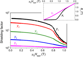
Figure 9. Shielding factors (symbols) measured in the transverse-field configuration by the five Hall probes placed along the cup's axis at T = 30 K. In the inset, the magnetic induction curves measured by the Hall probes located at positions y1 and y5 are plotted.
Download figure:
Standard image High-resolution imageLikewise in the axial-field configuration, in the low field range the shielding performance mainly depends on the sample shape. Indeed, the SF dependence on the distance from the closed extremity is still suitably described by the analytical expression calculated in [46, 47] for the transverse field attenuation by a superconducting cup in Meissner state:

being y the distance from the center of the closure cap.
Fixing on y2, y3 and y4 positions, we obtained  = 3.1,
  = 3.2 and
  = 10.0, in well agreement to the corresponding experimental ratios: 3.2, 2.9 and 9.1, respectively.
On the other hand, the large values of in-field Jc guarantee a smooth decrease or even a flat behaviour of the SF versus μ0Happl curves up to high applied fields.
As we did in the axial-field configuration, we defined three threshold fields, μ0Happl,lim⊥, as the applied field above that the shielding factor goes below 40 (for position y1), 20 (for position y2) and 7 (for position y3). In figure 10, μ0Happl,lim⊥ values are plotted as a function of temperature. As can be seen, near to the cup's closed edge (position y1), at 20 K SF is over 40 up to μ0Happl = 0.8 T, while in the same field range it is over 7 in correspondence to the cup's centre (position y3).

Figure 10. Temperature dependence of the threshold applied fields, μ0Happl,lim⊥, above which the shielding factor drops below 40 (for position y1, figure (a)), 20 (for position y2, figure (b)) and 7 (for position y3, figure (c)). Measurements were performed in the transverse-field configuration and the dashed lines are a guide to the eye.
Download figure:
Standard image High-resolution image
4. Conclusions
With the aim of obtaining a superconducting magnetic shield with small height/lateral dimension aspect ratio and significant SFs for different orientations of the external field, we fabricated an MgB2 cup-shaped shield via mechanical machining of an MgB2 bulk cylinder produced by spark plasma sintering of BNh-added MgB2 powder.
Large Jc values, which are essential for reaching a high magnetic-shielding capability, were obtained by a careful selection of the starting powder operated by x-ray diffraction analysis. Jc homogeneity was also proved by the agreement between the values measured on a small sample cut from machining residual parts and those obtained from the whole cup characterization. However, no clear indication on a prevalent pinning mechanism was given by the analysis of the pinning forces, but different mechanisms seem to be simultaneously active.
Shielding properties of the cup-shaped shield were investigated in both axial- and transverse-field geometries as a function of temperature, applied magnetic field and Hall-probe position along the sample's axis. Despite a height/external-radius aspect ratio of only 2.2, in the axial-field configuration, inside the cup and 1 mm away from its closed extremity, we measured SFs exceeding 104 at T = 20 K up to μ0Happl = 1.8 T. Moreover, in the same temperature and field region, SFs > 102 still persisted in the whole inner half of the cup. In addition, the range of external fields where such efficient shielding occurred is much larger than that expected on the basis of the modelling approach and related parameters reported in [18]. This result proves the high influence of the quality of the raw MgB2 powder on shield performance.
Although the transverse-field geometry intrinsically limits the shield performance [29], the in-field Jc of the sample allowed SFs over 40 to be still measured at T = 20 K up to μ0Happl = 0.8 T at a distance of 1 mm from the cup closure.
Further improvements in the shielding performance are expected by further enhancing the critical current density or by superimposing additional superconducting [29] or ferromagnetic [21, 50, 51] layers. On the other hand, an increase of Jc could favour flux-jump occurrence, limiting the practical applications of MgB2 shields. Thus, minimizing this phenomenon, without compromising Jc values and shielding performance, is the next challenging goal in this research field.
Acknowledgments
VB and MT acknowledge partial support from the 'Departments of Excellence' (L. 232/2016) grant, funded by the Italian Ministry of Education, University and Research (MIUR), and from the project BIOMB (Reference Number 4114) funded by the consortium M-ERA.NET 2. Romanian team gratefully acknowledges UESFISCDI, projects POC 37_697 No. 28/01.09.2016 REBMAT, 74/2017 cofunding M-ERA.NET 2 - BIOMB and Core Program PN19-03 (contract no. 21N/08.02.2019) and the consortium M-ERA.NET 2, project BIOMB.