


Abstract
The nonreciprocal properties of spin waves in metallized one-dimensional bi-component magnonic crystal composed of two materials with different magnetizations are investigated numerically. Nonreciprocity leads to the appearance of indirect magnonic band gaps for magnonic crystals with both low and high magnetization contrast. Specific features of the nonreciprocity in low contrast magnonic crystals lead to the appearance of several magnonic band gaps located within the first Brillouin zone for waves propagating along the metallized surface. Analysis of the spatial distribution of dynamic magnetization amplitudes explains the mechanism of dispersion band formation and hybridization between magnonic bands in magnonic crystals with metallization.
Export citation and abstract BibTeX RIS

Content from this work may be used under the terms of the Creative Commons Attribution 3.0 licence. Any further distribution of this work must maintain attribution to the author(s) and the title of the work, journal citation and DOI.
1. Introduction
The nonreciprocal properties of waves of different nature can have various origins and can be manifested as the dependence of a dispersion relation on the wave propagation direction, i.e. ω(k) ≠ ω(− k), where ω is the angular frequency and k is a wavenumber. The nonreciprocal properties of electromagnetic waves are often related with the magneto-optical interaction, which breaks the time reversal symmetry [1–4], a necessary condition of nonreciprocity (apart from broken space inversion symmetry). The discovery of nonreciprocity in photonic crystals (PCs) has opened new paths for the design of integrated photonic devices (like isolators and circulators) that have great potential for integration with semiconductor technology [5–7]. Thus PCs with nonreciprocal properties are intensively studied and the accompanying effects of electromagnetic unidirectionality, like frozen modes and slow light phenomena, have already been explored [8]. The nonreciprocal property has also been exploited in PCs with a topological one-way edge state [9, 10]. In these structures, an electromagnetic wave is transmitted in one direction and is very resistant to scattering on defects and roughness due to the prohibited propagation in the opposite direction. More complicated photonic structures with indirect interband photonic transitions [11], plasmonic systems [12] and metamaterials [13] were also investigated.
The spin wave (SW) in the magnetostatic limit (a long wavelength limit, when exchange interactions are negligible and, on the other hand, the magnetostatic approximation is still valid [14]) propagating in the in-plane direction of the film, perpendicular to the in-plane external magnetic field that possesses a nonreciprocal property, although its dispersion relation is reciprocal [15]. The amplitude of the dynamic component of the magnetization vector of this SW is localized near one of the surfaces of the film, depending upon the direction of the propagation. A change of the direction of the propagation (or alternatively, a change of the direction of the external magnetic field) will cause the localization of the SW to move to the opposite surface of the film. Such a SW is called a magnetostatic surface spin wave (MSSW) or Damon–Eshbach wave [14, 15]. Any kind of asymmetry of the film or its surrounding should cause an emerging of the nonreciprocal dispersion relation. In that sense, it is analogous to the photonic case, where spectral nonreciprocity appears when both the time and space inversion symmetries [16] are broken.
The MSSW propagating in a ferromagnetic film covered on one side by a perfect electric conductor (PEC) (i.e. a metal with infinite conductivity) in the direction perpendicular to the in-plane bias magnetic field, will also possess a nonreciprocal dispersion [17]. Metallization strongly affects the SW propagating in the direction that has a localization corresponding to the metallized surface, while the MSSW propagating in the opposite direction is almost unaffected. This nonreciprocal property of SWs still exists if the finite conductivity of the overlayer [18–20] or exchange interaction [21] are taken into account. In the first case, the nonreciprocal dispersion exists only for a limiting range of wave vectors, while for the second one, the localization type can change. Investigations of the nonreciprocal propagation of SWs have been developed in various semi-infinite ferromagnetic structures: layered, thin film and periodically corrugated. Potential applications of the nonreciprocal effects have been discussed in [22, 23].
Magnonic crystals (MCs), which are the magnetic counterparts of PCs [24], are promising new materials for manipulating a flow of SWs, similarly to PCs which can mould the flow of light. Thus, MCs are regarded as the main building blocks of magnonics: an emerging field of research aiming at fast nanoscale processing of the information with the use of SW dynamics [25, 26]. In this paper, we will study the nonreciprocal properties of SWs propagating in thin films of MCs, with space inversion symmetry broken by a metallic overlayer. The homogeneous yttrium iron garnet (YIG) film in contact with a metal grid has already been studied in transmission measurements [27–29]. The magnonic band gaps (MBGs) have been observed but the influence of the nonreciprocity was not discussed. The finite conductivity of the metal grid was considered in [30], where the strong nonreciprocity of the SW damping was predicted. The influence of nonreciprocity caused by a metal overlayer on SW Bragg resonances in YIG film with a lattice of etched grooves with the period a was recently studied experimentally [31, 32]. It was shown that if a dielectric spacer with thickness h is inserted between the YIG film and the metal overlayer, MBGs were detected only for SWs with wavenumbers kn > 1/h, where the effect of finite conductivity is strong and when the incident k+ and reflected k− waves have a similar frequency and fulfil the approximate Bragg diffraction condition (see figure 3 in [32]):

where n is an integer number. For SWs with wavenumbers k < 1/h, a nonreciprocity in dispersion leads to a sufficiently big difference in the wavenumbers of k+ and k− waves. It was concluded that in MCs with a metal overlayer, the Bragg resonances determined by equation (1) could not be observed for nonreciprocal waves [32].
However, in this paper we will show that the formation of MBGs in a media with a nonreciprocal property is possible and it exists when the incident and reflected SWs fulfil the so-called exchange Bragg condition [1]

We will show and explain that this MBG will appear inside of the Brillouin zone (BZ) and its indirect band gap. We also show that in the part of the SW spectra corresponding to the half of the BZ, more than one MBG can exist.
2. Method
A finite element method (FEM) has been implemented in the frequency domain to solve the Landau–Lifshitz (LL) and Maxwell equations to find the dynamical components of the magnetization vector ( m) and to obtain the dispersion relation of one-dimensional (1D) bi-component MC, shown in figure 1. In the frame of this approach, the nonuniform spatial distribution of microwave magnetization, as well the coupling between the dipole and the exchange subsystems of the MC, can be taken into account [20, 33]. This method can be used to predict the SW spectra in MCs with nano- and meso-scale periodicity and finite thickness. It is an important extension of the methods used previously in theoretical studies of nonreciprocal effects in magnonic structures [22, 34].
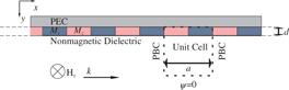
Figure 1. A structure of 1D MC with a layer of a PEC on the top surface. The MC is composed of alternating, infinitely long ferromagnetic stripes that have different saturation magnetizations M1 and M2. The bias magnetic field H0 is directed along the z-axis. The SWs propagate along the x-axis. The rectangular unit cell used in numerical calculations is marked by a dashed line. The PBC are used along the x-axis.
Download figure:
Standard image High-resolution imageThe LL equation of motion for magnetization vector M(r,t) is

where Heff denotes the effective magnetic field acting on the magnetization, μ0 is the permeability of a vacuum and γ is a gyromagnetic ratio, r is the position vector and t is time. The effective magnetic field is composed of the bias, exchange and demagnetizing fields. In the magnetostatic approximation (i.e. neglecting dynamical coupling of the magnetic and electric fields), the demagnetizing field is a gradient of the magnetostatic potential ψ. As a consequence, the Gauss law can be written as

where mx and my are the x and y dynamical components of the magnetization vector, respectively.
We assume that the bias magnetic field H0 saturates the sample along the z-axis. In addition, we neglect the higher order terms arising in the LL equation, i.e. we solve the system of equations in linear approximation [35, 36]. In MCs (figure 1) with the lattice constant a, the periodic boundary conditions (PBC) are used at surfaces parallel to the y axis and solutions of the LL equation are written according to the Bloch theorem as ϕ(x,y) = ϕ'(x,y)eikx, where ϕ' = m'x, m'y, ψ' are periodic functions of x. We look for solutions in the form of monochromatic SWs:  .
.
The continuity of the normal component of the magnetic induction By is required by electromagnetic boundary conditions, thus the By has to be zero on the top boundary of MCs with a PEC:

The electromagnetic boundary conditions require also that the magnetostatic potential should vanish in infinity in a dielectric substrate. To mimic this condition in the FEM, the Dirichlet boundary condition (ψ' = 0) was used at the bottom border of the computational unit cell, which is far away from the MC (figure 1). The boundary conditions for the dynamic components of the magnetization vector are imposed only via the LL equation; it provides zero of the first derivative of the dynamical magnetization with respect to the normal to the surface.
Using the Bloch theorem, a linearized LL equation complemented by Maxwell equations define the eigenvalue problem, which is solved by the FEM with the use of COMSOL 4.2 software. The eigenvectors represent the spatial distribution of dynamical components m'x, m'y and ψ'. Since the structure is periodic in the real space with a periodicity of a, the eigenvalues (frequencies of SWs) possess the periodicity in the 1D reciprocal space characterized by the period  .
.
3. Results
To make the specific properties of nonreciprocal SW spectra clearer, we will discuss two types of 1D MCs, which are characterized by low ΔM ≪ M1,2 and high ΔM ∼ M1,2 magnetic contrasts (ΔM = |M1 − M2|, M1 and M2 are saturation magnetizations of stripe 1 and 2) [37]. 1D MC with low magnetic contrast consists of stripes of the same thickness d = 70 nm, width w = 300 nm (lattice constant a = 600 nm), γ = 182.2 GHz T−1 and the exchange constant Aex = 7 × 10⁻¹¹ J m−1 but different saturation magnetization: M1 = 0.9 × 10⁶ A m−1 and M2 = 1.0 × 10⁶ A m−1. These values can correspond to iron and nickel alloys with various compositions [38]. As an example of MC with ΔM ∼ M1,2, we will address the structure composed of Co and Py stripes, which has already been investigated theoretically and experimentally [34, 39] with parameters M1 = 1.25 × 10⁶ A m−1, M2 = 0.65 × 10⁶ A m−1, Aex,1 = 2.88 × 10⁻¹¹ J m−1, Aex,2 = 1.11 × 10⁻¹¹ J m−1, γ = 182.2 GHz T−1, w = 250 nm, a = 500 nm, d = 30 nm. All calculations were done for the external magnetic field μ0H0 = 0.1 T.
At first, we calculate the dispersion curves within the first BZ for low magnetic contrast structure. The results are shown by dots in figure 2(a). For convenience, the SW dispersion for a uniform magnetic film with saturation magnetization MS being an average of M1 and M2, MS = (M1 + M2)/2 = 0.95 × 10⁶ A m−1 and other chosen parameters, is shown by the thick solid line. Two horizontal dashed lines pointing at fS and fex are used as reference lines. They correspond to frequencies of a short wavelength limit for MSSW (without exchange contribution) in magnetic film with a nonmagnetic dielectric surrounding 2πfS ≡ ωS = ωH + ωM/2 [15] and first exchange spin standing wave resonance mode  , where ωH = γμ0H0, ωM = γμ0MS,
  and N = 1 [20, 33]. The metallization introduces strong nonreciprocity in the SW spectra of thin film. The MSSW group velocities (
 ) at k → 0 are different for opposite directions of propagation, |V+g| ≈ 3.1 km s−1 and |V−g| ≈ 5.6 km s−1. We can also see that MSSW propagating along the metallized surface (i.e. for k−; their localization properties will be discussed later in the paper) possesses strong hybridization with the first exchange standing mode fex, leading to the exchange gap Δfex formation at frequency fex and k ≈ −0.7π/a, similar to the case of uniform ferromagnetic film [33].

Figure 2. (a) The calculated magnonic band structure (dots) of the 1D MC with small magnetic contrast. For convenience, the position of the upper frequency limit for MSSW fS and the frequency of the first exchange standing SW fex are shown for not metallized uniform magnetic film with structural parameters defined for MC with average magnetization  . The dispersion of metallized homogeneous ferromagnetic film like this is plotted by a thick continuous line, additional thin continuous lines present solutions folded to the first BZ only for primary branches, they are marked as ni±. The solid black dots described by ka – kcII and vertical lines indicate the points for which profiles in figure 3 are plotted. (b) The dispersion relation of Co/Py (high magnetic contrast) 1D MC with one side metallized (solid lines) and with both dielectric surroundings (dashed lines).
Download figure:
Standard image High-resolution imageThe periodicity of the structure leads to the appearance of the back-folded bands. For |k| ⩽ π/a and the frequency interval from 10 to 26 GHz shown in figure 2(a), only back folded waves travelling along non metallized surface (i.e. travelling in the k+ direction) and the first exchange standing mode take part in an interaction with SWs propagating along the metallized surface (i.e. travelling in the k− direction). In figure 2(a), dispersion curves corresponding to the MSSW of uniform film travelling along free surface (k+) and having its origin at kn = −(2πn)/a are shown by thin solid lines with numbers n = 1+...4+, where n corresponds to the order of BZ and index ' + ' pointed waves travelling along the positive direction of the x-axis. Dispersions of these waves are folded back to the first BZ and these could be interpreted as MSSWs in unmetallized uniform film with the wavenumbers shifted by the reciprocal lattice vector kn. At points where dispersion of these waves cross the dispersion of an n0− wave, the condition (2) is fulfilled and resonance scattering leads to MBGs appearance.
Among these Bragg resonances, we can distinguish two types. For the first one, nonreciprocity of SW propagation is not necessary, while for others it plays an important role. The Bragg resonances of the first type arise due to the interaction of the first standing SW resonance mode, fex with reflected MSSW travelling along the unmetallized surface (in the positive x direction). Due to exchange interactions, dispersion curves for MSSW do not have frequency limit fS for k → ∞, as it is seen from curves pointed by n = 1+,...,n = 4+, which are shifted above the limiting frequency fS and condition (2) can be fulfilled at frequencies close to fex. An example of the resonances of the first type is shown by the rectangular frame in figure 2(a) with inset, which shows an enlarged view of the dispersion. This resonance is similar to the resonance between two electromagnetic waves, with different polarizations in PC, from which at least one is folded-back to the first BZ [1, 3].
The resonance of the second type appears only in nonreciprocal structures. It corresponds to the interaction of SWs travelling along metallized and unmetallized surfaces under condition (2) (see regions of the SW spectra marked by circles). One can see the MBG opening in pointed regions. The values of the MBG diminished as the number n increases from n = 1+ to 3+. This feature is due to the decreasing of the overlapping integral of dynamic magnetizations and fields of interacting quasi-surface SWs as their localization near opposite surfaces become stronger with an increase of the wavenumber.
One of the specific features of MBGs opening at resonances (2) is the indirect character of gaps. It means that points with Vg = 0 on dispersion curves are characterized by different wavenumbers and it also reflects the loss of symmetry of the SW spectra in the nonreciprocal structure: ω(k) ≠ ω(− k). The indirect character is more evident for larger MBGs (correspondent to gaps with lower numbers n) (figure 2(a)). Because the value of the MBG increases with increasing the value of magnetic contrast ΔM [37], one can expect that the indirect character of MBG in high contrast MC covered by PEC will be more bright.
Now we consider high contrast MC. In figure 2(b), the calculated SW spectra for high contrast MC contacted with one PEC and with both dielectric surroundings are shown by solid and dashed lines, respectively. For high contrast MC, an approach based on the use of the spectra of the partial waves of the uniform film with averaged saturation magnetizations MS is not so obvious, as it was in the case of low contrast crystal. The SW dispersion calculated for MC with dielectric surroundings is reciprocal and MBGs between the magnonic bands are present with minimum and maximum (points 1 and 2 in figure 2(b)) at the BZ border according to the condition (1). The MPG calculated for the same MC with PEC has a nonreciprocal property with a pronounced shift of the maximum (or minimum) of the first (or second) band from the BZ border (points 3 and 4 in figure 2(b)). For the chosen parameters, the minimal energy state of the high energy branch and the maximal energy state of the low energy branch are characterized by wavenumbers k3 ≈ −0.7π/a and k4 ≈ −0.2π/a and MBG has the width Δf ≈ 1.1 GHz. The interesting point is that the metallization of the MC increases the group velocity of the higher bands, e.g. in proximity of point 4 in figure 2(b). This is an effect of the induced hybridization between the first and the second band. This may imply advantages for applications in magnetic field sensors, which require a high field sensitivity and a sharp band gap absorption peak [28].
To gain insight of the character of propagating SWs from different bands in the BZ, let us consider the spatial distribution of the real part of the periodic Bloch function of the dynamic magnetization component m'x(x,y) ( ) for low magnetization contrast MC. In figures 3(a)–(c), the function
  of the two lowest modes across the MC thickness and along the periodicity are plotted for three wavenumbers ka, kb and kc indicated in figure 2(a) by vertical dashed lines. The paths in MC along which the plots are made are marked by vertical dashed lines in figure 3(d).

Figure 3. (a)–(c) The spatial distribution of the magnetization component  for three values of ki wavenumber (in units of π/a) across the thickness of the MC (left plots) and along the x-axis (right plots). The wavevectors are indicated by the vertical dashed line on the figure 2(a). The path along which the distributions are plotted is indicated on the unite cell of MC by dotted lines in (d).
Download figure:
Standard image High-resolution image
For ka = −0.28π/a, the amplitude of SW is a quasi-uniform function of x for the mode I (figure 3(a)). The distortion from the uniform shape is due to different values of saturation magnetizations in materials 1 and 2. The distribution of the second mode has two nodal points along the x-axis. This suggests that its effective wavenumber is larger than π/a and appears as a solution in the first BZ due to the back-folding of the band. The effective wavenumber is kaII = ka + 2π/a. The dynamic component of the magnetization is neither uniform nor exponentially decaying across the thickness, as could be expected for the MSSW mode. This is ascribed to the role of exchange interactions, which have a minor influence on the dispersion relation but are sufficient to modify the profile of modes, as it was shown in [20, 33] for thin films.
For kb = −0.36π/a (figure 3(b)), the hybridization is very strong. The SW amplitude modulus shows the larger amplitude of the first mode in material with low saturation magnetization and of the second mode within material with higher saturation magnetization. For kc = −0.44π/a (figure 3(c)), the distortion from the quasi-uniform distribution of the second mode along the x-axis suggests that hybridization between the first and second mode is still present and on the other hand, the hybridization between the second and third modes starts to play a role. It is due to the non-symmetrical band structure when the density of MBGs within one BZ is increased. We might observe hybridizations between more than two SWs.
4. Conclusions
We have investigated theoretically the impact of a perfect metal overlayer on the SW dispersion relation of 1D bi-component MCs with high and low magnetic contrasts. In both cases, we have found the nonreciprocal band structure where the Bragg resonances of the nonreciprocal SWs take place, under fulfilment of the so-called exchange Bragg condition and characterized by the indirect MBG shifting from the BZ border. Specific features of nonreciprocity in low contrast MCs lead to the appearance of several MBGs located within the first BZ for waves propagating along the metallized surface, while they are absent for waves travelling along the unmetallized surface of MC. This property can lead to multimode hybridization effects, which are only possible because of the periodicity of the system and the folding of the dispersion branches to the first BZ.
These results are important from the point of view of an explanation of existing experimental results [27, 28, 31] and potential applications of MCs. Our results pointed out that for high sensitive magnetic field sensors proposed recently [28], a shape of magnonic bands near the MBG edges will have an important influence on its sensitivity. Its sensitivity might substantially depend on the direction of the propagation and the design of the device. Additional studies, theoretical and experimental, are necessary to check if the structure proposed in this paper (1D bi-component MC but an array of stripes, with the homogeneous metal plate on its top or bottom) can have better characteristics, rather than a lattice of metallic stripes on homogeneous ferromagnetic film [28]. The nonreciprocal properties of the magnonic band structure can also be useful to design miniaturized microwave isolators and circulators: essential elements in microwave technology. For these applications, MCs with the nonreciprocal magnonic band structure can also have other designs, without asymmetry along its thickness, as proposed in this paper. The requirements are the same, breaking the time and space inversion symmetry. In [40], the array of the monodomain ferromagnetic nanodiscs with perpendicular magnetic anisotropy was considered as MCs with nonreciprocal SW dispersion. The space inversion symmetry breaking was provided by the complex unit cell combined with a magnetic configuration, this puts high requirements on the technology for its fabrication. The interesting point is that the structure proposed in [40] can operate without an external magnetic field and possesses a property of re-programmability, i.e. the dynamical response of the structure can be changed through switching between stable magnetic configurations. The fabrication of 1D MCs, as proposed in this paper, is much easier; they can also operate without an external magnetic field due to a shape anisotropy. Here, the nonreciprocal property can also be combined with re-programmability [41–44].
In order to observe the nonreciprocal magnonic band structure experimentally, we need to consider the influence of finite conductivity and damping of SWs. The finite conductivity, overlayer thickness, skin depth and MC lattice constant must be properly adjusted to receive the influence of the metal layer mainly on dispersion but not on the losses of MSSW [18]. These requirements demand a well designed structure of a MC to observe the indirect MBG formation in the first BZ with the Brillouin light scattering measurements [45] or with the broad-band ferromagnetic resonance [46]. When the finite conductivity is taken into account, the effect of metallization disappears for waves with large wavevectors. Thus, on one hand the lattice constant needs to be chosen so the wavevector is big enough to measure it, but small enough that the effect of metallization is still present.
Acknowledgments
We acknowledge the financial assistance from the European Community's Sevenths Framework Programme (FP7/2007-2013) under grant agreement no. 247556 (People) for NoWaPhen project and under grant agreement no. 228673 for the Magnonics project. This work was also partially supported by MIUR-PRIN 2010-11 Project2010ECA8P3 'DyNanoMag' and by NCN of Poland project DEC-2-12/07/E/ST3/00538. MM and MK wish to thank Dr Wojciech Śmigaj for helpful discussions.