


Abstract
We describe a method to trap, transport and release microscopic particles in a viscous fluid using the hydrodynamic flow field generated by a magnetically propelled colloidal ribbon. The ribbon is composed of ferromagnetic microellipsoids that arrange with their long axis parallel to each other, a configuration that is energetically favorable due to their permanent magnetic moments. We use an external precessing magnetic field to torque the anisotropic particles forming the ribbon, and to induce propulsion of the entire structure due to the hydrodynamic coupling with the close substrate. The propulsion speed of the ribbon can be controlled by varying the driving frequency, or the amplitude of the precessing field. The latter parameter is also used to reduce the average inter particle distance and to induce the twisting of the ribbon due to the increase in the attraction between the rotating ellipsoids. Furthermore, non magnetic particles are attracted or repelled with the hydrodynamic flow field generated by the propelling ribbon. The proposed method may be used in channel free microfluidic applications, where the precise trapping and transport of functionalized particles via non invasive magnetic fields is required.
Export citation and abstract BibTeX RIS

Original content from this work may be used under the terms of the Creative Commons Attribution 3.0 licence. Any further distribution of this work must maintain attribution to the author(s) and the title of the work, journal citation and DOI.
1. Introduction
The trapping and transport of microscopic entities via hydrodynamic flow is an emergent field of research that could lead to novel and exciting developments in lab on a chip devices, such as the controlled release and site specific delivery of chemical or biological cargos. In microfluidic systems, where pressure fields are used to displace nanoliter volumes of reagent in  wide channels, the trapping, assembly and positioning of microspheres via hydrodynamic flow has been demonstrated in different works [1–6]. The time reversal nature of fluid flow at low Reynolds (Re) number [7] allows for realizing precise single particle operations at the microscale, since inverting the fluid current does not lead to the formation of swirls or turbulence that can randomize the motion of the dispersed particles.
An alternative approach that is gaining much attention is the use of externally driven micropropellers capable to drag and transport microscopic objects using the hydrodynamic flow generated by their movement. This strategy does not require lithographic confinement or externally imposed pressure fields, but a suitable actuation scheme that enables net propulsion at low Re number, avoiding reciprocal motion, namely periodic backward and forward body displacements [8]. Recent examples in this direction include the use of magnetically driven nanorods [9], colloidal rotors [10–12], or magnetic particles driven above ferromagnetic structures [13–16]. In contrast to other actuation schemes, for instance the ones based on chemical reactions [17], electric [18], acoustic [19] or optic fields [20], magnetic fields have the advantage of not directly altering the dispersing medium, although they require magnetic parts within the prototypes [21–28].
In this article we demonstrate a method to assemble and propel a colloidal ribbon, which is later used to trap and release non magnetic objects in a viscous fluid by using the hydrodynamic flow that it generates. The ribbon is composed by a collection of hematite microellipsoids assembled and propelled upon application of an external precessing magnetic field. The applied field aligns the particles and forces them to rotate in a plane perpendicular to the close surface. The ribbon translates as a whole at a constant speed due to the collective rotations of the composing particles, generating a net flux with a major component perpendicular to its long axis. This hydrodynamic flow is used to manipulate unbound non magnetic particles in a fluid, by attracting or repelling them depending on the sense of rotation of the ellipsoids forming the ribbon. We develop a theoretical model that allows us to compute the generated hydrodynamic flow by using analytical arguments, and to obtain a good agreement with the experimental data.
2. Experimental
The colloidal ribbon is composed of hematite (α-Fe2O3) microellipsoids, synthesized following the method developed by Sugimoto and coworkers [29]. The realized particles are monodisperse prolate ellipsoids with a major axis (two minor axes) equal to  (
( resp.). During the synthesis, the particles acquire a permanent moment oriented mainly perpendicular to their long axis, as shown in the schematic in figure 1(a). The non magnetic particles used as a cargo are commercial aqueous suspensions of monodisperse silicon dioxide particles (44054 Sigma-Micro, Sigma-Aldrich), having
  in size. Before the experiments, we first disperse the particles in high deionized water (milliQ, Millipore), stabilize them with sodium dodecyl sulfate (0.11 g of SDS for 80 ml of water) and finally adjust the pH of the solution to 9.5, by adding different aliquots of tetramethylammonium hydroxide. This procedure avoids irreversible sticking between the particles and to the glass surface, induce by attractive Van der Waals interactions. The resulting solution is introduced in a sealed capillary chamber (inner dimensions
  , CMC Scientific), where the particles sediment due to density mismatch. After few minutes, the ellipsoids float at a certain distance above the bottom plate due to balance between gravity and electrostatic repulsive interactions with the surface. We visualize the particle dynamics with an upright optical microscope (Eclipse Ni, Nikon) connected to a CCD camera (Balser Scout scA640-74fc) equipped with a
  1.3 NA oil immersion objective.
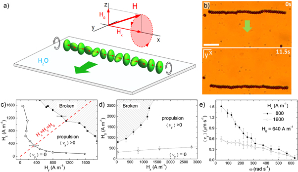
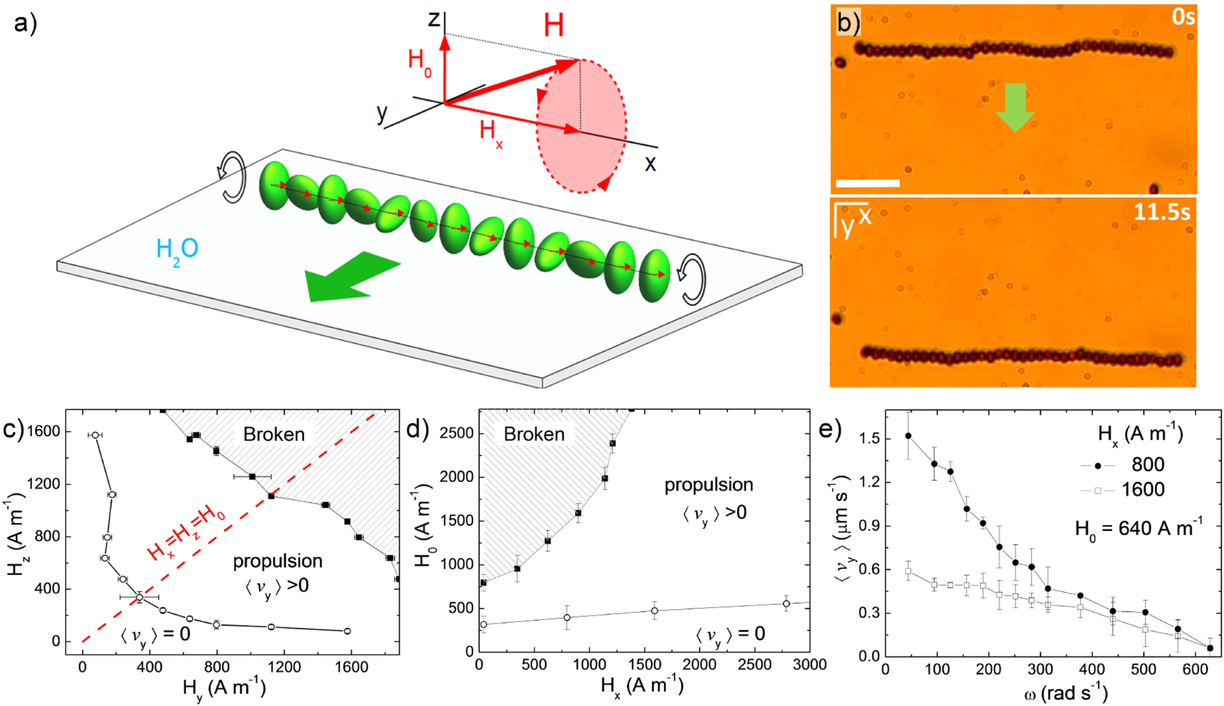
Figure 1. (a) Schematic illustrating a magnetic ribbon composed of 13 ferromagnetic ellipsoids, propelling due to a precessing magnetic field  , with amplitudes
  and angular frequency ω; here
  . (b) Sequence of microscope images showing the transport of one ribbon upon application of a precessing field with
  ,
,  , and
, and  . The corresponding video can be found in the supporting information which is available online at stacks.iop.org/NJP/19/103031/mmedia. (c) and (d) Diagrams in the
  plane (c) for
  and in the
  plane (d) both for
  . The diagrams show the regimes where the ribbons break, propel (
 ) or stop moving (
 ). (e) Average speed
  of a ribbon versus driving frequency ω for two amplitudes of the applied field Hx, where
  .
.
Download figure:
Standard image High-resolution imageThe precessing field used to propel the magnetic ribbon is generated with a custom made system composed by three coils with their main axis aligned along the three orthogonal directions ( ). The whole experimental setup is oriented in such a way that the
  axis coincides with the direction of the Earth magnetic field. In order to generate a rotating magnetic field in the (
 ) plane, i.e. perpendicular to the glass substrate, two pairs of coils are connected to a power amplifier (IMG STA-800, Stage Line) that is commanded by an arbitrary waveform generator (TGA1244, TTi). To apply a constant field along the
  direction, the third coil is connected to a DC power supply (EL 302RT, TTi).
3. Ribbon assembly and propulsion
In absence of any external field ( ), the hematite ellipsoids spontaneously assemble into chains or rings due to attractive dipolar interactions arising from their permanent magnetic moments [30]. In a previous work [31], we investigated the orientational dynamics of individual ellipsoids under a static external field and measured an average magnetic moment of
  . Since this moment is perpendicular to the long axis of the ellipsoid, when chaining the particles arrange side by side, forming a ribbon. This configuration is similar to that previously found for ferromagnetic Janus rods, that also showed a magnetization along their short axis [32]. The assembled structure however is rather fragile, and can be easily broken by thermal fluctuations. As a matter of fact, the interaction energy between two isolated ellipsoids at close contact can be estimated as:
  , being
  , kB the Boltzmann constant and
  the room temperature. This interaction may increase within the ribbon due to nearest particles, but still it would be of the order of few
  .
.
We strengthen and propel the ribbon along a defined direction, in this particular case the  axis, by applying an external precessing magnetic field, composed by a static component of amplitude Hx and aligned along the
  -axis, and a rotating one polarized in the perpendicular plane
  , figure 1(a). The applied field is thus given by:
  , where
  corresponds to the amplitude of the rotating field and ω its angular frequency. This field has different effects on the chain of ellipsoids. First, the component Hx orients the ribbon along the x axis, minimizing the magnetostatic and the effective demagnetizing energy densities [31]. This effect makes the chain stiffer, as it further aligns the particle moments along the ribbon axis. Second, the rotating component applies a net torque to the ellipsoids,
  , forcing them to rotate around their short axis. The existence of this torque is due to the fact that, within each ellipsoid, the permanent moments are not exactly perpendicular to the particles' long axis as in an ideal situation, but they have a narrow tilt angle distribution that arises from imperfections during the chemical growth process. This distribution was assessed for isolated particles by measuring the angles between the long axis of the ellipsoids and the direction of a constant applied field, and it is shown in the supporting information5
. The rotation of the individual ellipsoids within the ribbon is essential for inducing its net displacement. Since the ellipsoids are close to a surface, their rotational motion is rectified in a rolling dynamics, and the ribbon moves as a whole at a constant average speed and along a direction that is dictated by the chirality of the rotating field, figure 1(b).
, forcing them to rotate around their short axis. The existence of this torque is due to the fact that, within each ellipsoid, the permanent moments are not exactly perpendicular to the particles' long axis as in an ideal situation, but they have a narrow tilt angle distribution that arises from imperfections during the chemical growth process. This distribution was assessed for isolated particles by measuring the angles between the long axis of the ellipsoids and the direction of a constant applied field, and it is shown in the supporting information5
. The rotation of the individual ellipsoids within the ribbon is essential for inducing its net displacement. Since the ellipsoids are close to a surface, their rotational motion is rectified in a rolling dynamics, and the ribbon moves as a whole at a constant average speed and along a direction that is dictated by the chirality of the rotating field, figure 1(b).
We first vary the different amplitudes of the precessing field in order to determine the range of experimental values where the propelling ribbons are observed. In the diagram in figure 1(c), we keep constant the static field Hx while varying the ellipticity of rotating field, defined as  [33]. The red line cutting in half the diagram denotes the circularly polarized case where
  (
( ). The ribbon is propelled for both positive (
 ) and negative (
 ) values of β, while it breaks for large field amplitudes,
  . The ribbon rupture results from the fact that the magnetic torque is now able to spin the entire structure, and the ribbon behaves as a compact rod that tries to follow the conical precession of the field. However, the magnetic chain inevitably breaks when standing up due to the presence of the solid substrate and the action of gravity. Below
  , the magnetic actuation is too weak to induce any propulsive motion. When considering a rotating field circularly polarized (
 ), the propelling ribbons are stable for a wide range of values of Hx, as shown in figure 1(d). The tendency to break or to stop propulsion are found for large and small values of H0 respectively, in agreement with the previous graph. We note that
  was defined as the condition accomplished when the average translational motion of the ribbon cannot be distinguished by the one observed in absence of the precessing field, i.e. when the motion of the ellipsoids is due to sole thermal fluctuations.
The average speed of the ribbon  can be easily tuned by varying two control parameters, namely ω and Hx. We start by measuring the dependence of
  with ω, and at constant Hx, figure 1(e). For most of the magnetic propellers that are actuated by time dependent fields, the driving frequency is the natural parameter used to control their speed. The frequency allows for changing the particle dynamics from a synchronous regime, where velocity of the propeller is proportional to the driving frequency, to an asynchronous one, where
  decreases as ω increases since the propeller is slower than the field rotations. We find that, for our magnetic ribbons, the rotations of the ellipsoids are in the asynchronous regime for all the explored frequencies,
 ![$\omega \in [10,650]\,\mathrm{rad}\ {{\rm{s}}}^{-1}$](https://content.cld.iop.org/journals/1367-2630/19/10/103031/revision2/njpaa84f9ieqn49.gif) . In this regime of motion the phase angle ϕ between the direction of the magnetic field and the orientation of the permanent moment follows the Adler equation [34] with
. In this regime of motion the phase angle ϕ between the direction of the magnetic field and the orientation of the permanent moment follows the Adler equation [34] with  , being
  the critical frequency that separates the synchronous from the asynchronous motion. Solving the previous equation for
  gives the average rotational speed as
  [35]. Thus, in the asynchronous regime the hematite ellipsoids rotate with an angular frequency
  smaller than the driving frequency ω, showing characteristic 'back and forth' oscillations within the ribbon.
The relative low value of the average speed found, as compared to other magnetic rotors [36–40] results from both, the strongly constrained motion of the particles within the ribbon, and from the small tilt angle of their permanent moments. For  , the average speed
  decreases with ω, starting from
  (
( ) and reducing to zero at
  . From the data in figure 1(e) it also emerges that an increase in the amplitude of the in plane field Hx decreases the particle rotational motion and thus the velocity
  . However, both curves display similar trends beyond
  which could be an indication that a different mechanism such as magnetic relaxation [41] becomes dominant at high frequency.
We next characterize the average speed  and the deformation induced by the increase in the amplitude of the static component Hx, while keeping constant ω. The observed trend is similar to that of varying ω, since
  decreases as Hx increases, figure 2(a). However, as shown in the small schematic in figure 1(a), the field component Hx is also responsible for the degree of alignment of the particle moments, since it determines the cone angle of the precessional motion described by the ellipsoids. At high values of Hx, the average inter particle distance
  reduces linearly towards the the hard sphere limit
  , figure 2(b). A direct consequence of this compression is that the colloidal particles experience stronger dipolar attractions that forces them to rotate in a collective manner. Thus, the colloidal chain assumes a twisted conformation, with groups of particles rotating together. The ellipsoidal shape of the particles allows for characterizing this field induced distortion, and the wavelength of the twist can be measured in terms of the average number of particles contained in a complete turn. This number increases almost linearly with Hx, as δ reduces. For very large field values, all the ellipsoids within the ribbon try to rotate together, and the twisting reaches the size of the entire structure, while
  goes to zero. The twisted ribbon resembles the helical ribbon formed by paramagnetic colloids subjected to a precessing magnetic field [42]. However, in our case the pitch remains constant along the chain, and no transversal motion of domain walls was observed as in [42].
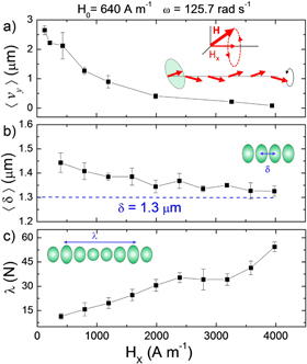
Figure 2. (a)–(c) Average translational speed  (a), inter particle distance
  (b) and wavelength λ (c) versus Hx for ribbons composed by hematite ellipsoids. The precessing field has
  and
and  . The small schematics in the images illustrate the effect of the component Hx on the alignment of the magnetic moments (a), the average distance δ (b) and the wavelength measured in terms of the number of particles N (c).
Download figure:
Standard image High-resolution image4. Transport of non magnetic colloids
The magnetic ribbons can trap and transport non magnetic particles by using the hydrodynamic flow generated by the rotations of the composing particles. We demonstrate this feature in figure 3(a), where we drive a colloidal ribbon close to a large silica particle of  diameter. We find that the non magnetic colloid can be either repelled or attracted when located in front or behind the propelling chain, respectively. Even though the ribbon has a finite extension, this length can be much larger than the silica bead diameter, and the latter can be stably trapped and transported when located close to the central part of the ribbon, see the corresponding supplementary video (see footnote 5). By tracking the relative distance
  between the particle and the central position of the ribbon, figure 3(b), we observe that in both cases, i.e. when located in front or behind the chain, the silica colloid reaches a constant distance from the center of the ribbon. When attracted, the non magnetic particles reaches the back of the chain and remains there as long as the precessing field is applied. Inverting the polarity of one of the two components of the rotating field, here
  , reverses the sense of motion of the ribbon. Now the cargo becomes repelled, moving away from the chain till reaching a mean distance of
  . The silica cargo can be further localized in a given place by applying a driving frequency higher than
  , so that the chain does not propel but it still generates an attractive flow in its back. An alternative way to trap the non magnetic object without moving it away from the observation area and keeping the frequency constant, would be to periodically switch the sign of Hy. This procedure would allow changing from attraction to repulsion and thus moving the particles back and forth along the same path, confining the colloid along a narrow line. We also find that this hydrodynamic trapping mechanism becomes less stable for shorter ribbons. As shown in figure 3(c), and corresponding VideoS3 (see footnote 5), when transported by a shorter ribbon composed of N = 9 particles, the silica colloid eventually escapes from the lateral direction. This indicates that the repulsive hydrodynamic flow is only strictly perpendicular to the ribbon long axis at its center, while it becomes tilted near the edge. This effect can be however minimized by placing the ribbon such that it attracts the non magnetic object at its center.
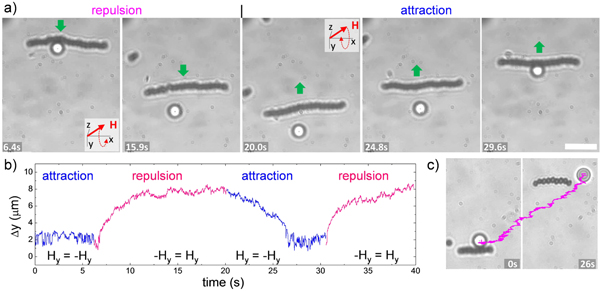
Figure 3. (a) Sequence of microscope images showing how the motion of one silica particle (diameter  ), placed above the glass surface, is controlled by a propelling ribbon subjected to a precessing field of amplitudes
  ,
,  and angular frequency
  . (b) Corresponding distance
  between the center of the ribbon and the center of the silica particle versus time. Blue (magenta) regions indicate hydrodynamic attraction (repulsion) induced by the translation of the ribbon. The reverse of the field Hy, that changes the polarity of the rotating field and consequently the propulsion direction of the ribbon is shown at the bottom of the graph. (c) Images showing two snapshots of one silica particle being repelled by a short ribbon composed of N = 9 hematite ellipsoids. The trajectory of the particle is superimposed as a magenta line.
Download figure:
Standard image High-resolution image5. Flow generated by the propelling ribbon
The magnetic ribbon generates a net hydrodynamic flow due to the rotation of the constituent particles. We model this flow by considering the translating chain of ellipsoids as a line of equally spaced particles that rotate close to a solid surface. Direct analytic expressions of the flow produced by this array can be obtained in the Stokes regime, by assuming that each particle has associated an hydrodynamic singularity placed below the solid surface and at the same distance from the solid wall. As described in [43], this singularity is composed by a rotlet, a stresslet and a source doublet. Thus, the velocity of the flow generated by one colloid rotating at an angular velocity Ω is given by the tensorial equation [43]:

Here r is the position vector from the center of the particle and R the position of its hydrodynamic image, which has an opposite sense of rotation. In this way the tangential component of the generated flow cancels at the interface. Equation (1) can be extended to derive the flow generated by an array of N rotors, aligned along the  direction, and rotating with an angular velocity
  , where the index
  . The rotors are placed at position
  , being hn their elevation from the surface. The velocity field at any point of space
  is given by:

It should be noted that our theoretical model considers only the hydrodynamic contribution, neglecting any further interaction between the particles. The magnetic interactions are important to assemble the chain of particles and to generate the net torque, but do not have any direct influence on the produced hydrodynamic flow. As a matter of fact, such interactions have been already addressed in a different context [30, 31], and here we assume that the ellipsoids rotates at an average angular velocity  . Using equation (1) it also possible to determine the average speed for a chain of spherical rotors in a similar way as done in [44], where paramagnetic colloids were magnetically assembled in chains that translated parallel to the surface and along their main axis. However, in our case this calculation may give rise to theoretical values different than the experimental ones due the non spherical shape of our ellipsoids and the asynchronous rotation resulting from the strong dipolar attraction between the particles.
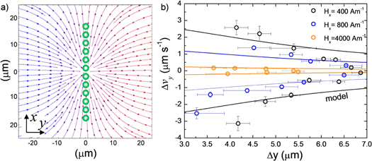
We test our model by first calculating the flow profile generated by a chain of rotors that moves towards the  direction, figure 4(a). As expected from the experimental evidence, the flow profile is attractive behind the propelling chain of particles (blue arrows), and repulsive in front of it (magenta arrows). Moreover, it radially converges toward the center of the chain, sign that tracer particles placed close to the border of the chain migrate toward the chain center when attracted, or are expelled from it when are repelled, as observed in figure 3(c).
Figure 4. (a) Streamplot of the flow velocity uy generated by a chain of N = 12 propellers translating from left to right. The velocity field was calculated at the same elevation of the chain, see model in the text. The flow is attractive behind the chain (blue arrows), and repulsive in front of it (magenta arrows). (b) Flow velocity uy versus distance  when the particle is repelled (
 ) or attracted (
 ) by a propelling ribbon driven by a precessing field with
  and angular frequency
  . Scattered points are experimental data taken at different amplitudes of the in plane field Hx. Continuous lines are multiple fits to equation (2) of the model.
Download figure:
Standard image High-resolution image
A quantitative comparison with the experimental data is shown in figure 4(b), where we measure the average speed of the non magnetic tracer particles as a function of the distance from the center of a ribbon, which is propelled at different speeds obtained by varying the amplitude of Hx. We then perform multiple fits to the experimental data (scattered data in figure 4(b)) by using equation (2) of the model. In all cases, the experimental parameters that we kept fixed are the radius of the rotating particles,  , their elevation
  , mean distance
  and the elevation of the silica particle
  . We then leave as the only adjustable parameter the average angular rotation of the ellipsoids
  , that is induced by the precessing field. The values of
  obtained from the fits are always smaller than the field frequency ω, confirming the fact that the particles rotates asynchronously with the driving field. For short distances or small speed of the chain (high values of Hx), there is a good agreement with the experimental data, even if the developed model present different approximations. At large separations between the ribbon and the silica particle, some deviations from the theoretical trend become visible. At such distances, thermal fluctuations may be strong enough to perturb the particle trajectory, or the effect of the finite size of the chain may become significant.
6. Conclusions
In this article we have demonstrated a method to trap and transport non magnetic objects in a viscous fluid by using a magnetically assembled and twisted chain of rotating ferromagnetic ellipsoids. The chain propulsion is induced by an external precessing field, that allows for tuning both the chain mean speed and the twisted conformation. We describe the generated hydrodynamic flow as the cooperative flow resulting from a one dimensional ensemble of microscopic rotors. Even though our theoretical approach uses far field approximations, it properly captures the physics behind the hydrodynamic trapping process. Further extension of this study may include the effect of the magnetic interactions between the particles and how these interactions lead to the twisted state. On the application side, our magnetic twisted ribbon may be potentially used in lab on a chip devices where precise transport of non magnetic objects is required for the delivery of drugs or chemicals attached to functionalized particles.
Acknowledgments
HMC and PT acknowledge support from the ERC starting Grant 'DynaMO' (No. 335040). FMP acknowledges support from the Ramón y Cajal program (RYC-2015-18495). PT acknowledges support from MINECO (FIS2016-78507-C2-2-P) and DURSI (2014SGR878). EN and IP acknowledge support from MINECO (Spain), Project FIS2016-78507-C2-2-P, DURSI Project 2014SGR-922, and Generalitat de Catalunya under Program 'ICREA Acadèmia'.
Footnotes
- 5
See supporting information for two videos illustrating the propulsion of one individual ribbon and the controlled hydrodynamic trapping on a silica microsphere.