

Abstract
Deep volumetric microscopy of live objects plays a critical role in biology and medicine. To this end, development of rapid and non-invasive optical methods for 3-dimensional (3D) imaging is still demanding. In this way, light-sheet fluorescence microscopy (LSFM) has emerged as a volumetric microscopy method having high spatial-temporal resolution for imaging of samples within dimensions from submicron to few centimeters with minimum induced photo damaging. Unique features of LSFM allow for its modification and deployments in various fields including developmental biology, pathology, and microfluidics. Considering the wide spectrum of LSFM users, this tutorial review article explains basic concepts and design considerations of LSFM and provides a detailed analysis of various optical configurations of LSFM. Major developments of LSFM for adoption in both research and clinical applications including tissue imaging, diagnostics, and cytometry are also explained. In addition, various designs of light-sheet fluorescent microscopes for use as a stand-alone microscopy unit and an add-on device are discussed.
Export citation and abstract BibTeX RIS
1. Introduction
Real-time and in vivo imaging of tissues and organs with high spatial resolution has gained a critical role in biology and medicine within the last decade. To obtain more realistic understanding about the behavior of biological objects such as cells and tissues, it is of utmost importance to investigate their biology in physiologically-relevant microenvironments.
Many biological phenomena such as developing embryos, neurons communications in brain, and cells' behavior in a tumor happen in a three dimensional (3D) microenvironment. In this way, having a high-speed noninvasive 3D-imaging method is very critical [1]. Obviously, traditional 3D imaging methods based on physical slicing a sample into thin slices [2] are not able to meet such requirements.
Optical sectioning is a necessity for any optical microscopy configuration to capture 3D images noninvasively. The most well known methods based on optical sectioning of samples are confocal [3] and multiphoton [4] microscopies that operate based on fluorescent labeling and point scanning of sample. In confocal fluorescence microscopy, sectioning is accomplished by actively suppressing any signal coming from out-of-focus layers [5]. Compared to 2D epi-fluorescent microscopy, confocal fluorescence microscopy provides advantages including the ability to control depth of field and enhance contrast by reducing background. However, it suffers from some limitations such as low imaging speed due to point scanning, and photodamage of sample because of undesired illumination of out of focus regions [6]. The limited penetration depth and high level of induced photodamage, i.e. photo toxicity, to sample in confocal microscopy have been addressed in multiphoton fluorescence microscopy using near-infrared excitation light that minimizes light scattering and also produce less photodamage [7]. However, the high cost of this microscopy method due to use of Titanium Sapphire Laser limits its accessibility. Although photodamaging is less pronounced in multiphoton microscopy compared to confocal microscopy, it still induces some levels of phototoxicity due to use of high power excitation light. It has been reported that after 1 h of multiphoton imaging, division in tumor spheroids could stop, while in ordinary excitation, cell division could be maintained for more than 24 h [8]. Besides, similar to confocal microscopy, point scanning procedure makes this method unsuitable for noninvasive studying of large or dynamic specimens in biology.
Light-sheet fluorescence microscopy has been recognized as an efficient novel method for noninvasive 3D microscopy of biological samples within the last 15 years. In contrary to point scanning microscopy, in which a sample is sequentially exposed and detected in a point-by point manner, a wide plane of sample is illuminated using a thin light-sheet (LS). At each step of illumination for optical sectioning, sample is moved and displaced with respect to LS. Emitted fluorescence light from illuminated plane is captured using an orthogonally oriented detection arm (figure 1). In this way, captured images from different depths of a sample are put together to create a final 3D image of whole sample.

Figure 1. Schematics of the basic working principles of LSFM based on focusing a thin light-sheet (LS) propagating through a sample along y-direction perpendicular to a detection objective along x-axis. The beam is reshaped to a light-sheet over z-y plane to generate an illumination plane within sample. Upon excitation a layer within sample, emitted fluorescence from confocal region of illumination and detection objectives is collected by a detection objective. The sample is moved with respect to LS, and in each step an image is captured from a certain depth of sample. 3D image of whole sample is constructed by stacking of 2D captured images to create the final 3D image.
Download figure:
Standard image High-resolution imageIn comparison to point scanning microscopes, LSFM significantly increases the imaging acquisition speed, table 1. Besides, the most noticeable feature of LSFM is remarkable reduction of photodamaging. Since illumination is confined only to a thin section of specimen, out of focus exposure is eliminated. Consequently, overall required illumination for imaging is reduced. Moreover, the use of two separate objectives for illumination and detection results in decoupled axial and transversal resolutions. Therefore, LSFM allows for 3D imaging of various relatively small and large specimens such as a single neuron [9] , embryos [10] and whole mouse brain [11].
Table 1. Comparison of different conventional microscopy methods benefiting the advantages of fluorescent labeling.
| Optical sectioning | Contrast | Penetration depth | Photo damaging | 3D imaging acquisition speed | |
|---|---|---|---|---|---|
| Epi-fluorescent microscopy | No | • | • | ••• | NA |
| Multiphoton microscopy | Yes | •• | ••• | •• | • |
| Confocal microscopy | Yes | ••• | • | ••• | • |
| LSFM | Yes | •• | ••• | • | ••• |
1.1. Background of LSFM
Light-sheet illumination was first introduced over a century ago in 1903 as ultramicroscopy by Siedentopf and Zsigmondy [12] when they were working for Carl Zeiss company. In their Ultramicroscope, sunlight was projected through a slit aperture to observe gold particles. The idea did not stimulate further developments until 1993, when it was reintroduced by Voie and colleagues as an imaging tool for orthogonal plane fluorescence sectioning (OPFOS) to visualize the morphology of guinea-pig cochlea [13]. OPFOS included all elements present in basic LSFM devices including laser source, beam expander, light-sheet generator via a cylindrical lens, specimen chamber, orthogonally illuminating sample with regard to detection arm, z-stack generation through specimen movement, and fluorescent labeling. The basic theory and design of LSFM were discussed in detail by Stelzer and Lindek in 1995, while they were developing an oblique illuminating confocal microscope to improve the axial resolution of confocal microscopy [14]. In their study, detection objective was mounted at 102° with respect to illumination objective. This system was known as confocal theta microscopy [14] that later created a foundation for their subsequent version of a LSFM device called selective or single-plane illumination microscopy (SPIM) in 2004 [10]. Moreover, Fuchs et al (2002) described an OPFOS-like device, which they called it a thin laser light sheet microscope (TLSM) to examine microorganisms in seawater [15]. Finally, the first use of LSFM for real-time in vivo imaging was reported in 2004 by Stelzer's group to investigate the embryonic development of Medaka and Drosophila [10]. Named as selective plane illumination microscopy (SPIM) by its developers, this technology created a turning point for the adoption of LSFM in high-speed imaging of live biological events.
To produce more uniform light-sheet excitation for improved imaging quality of large specimens Keller et al developed digital scanned laser light-sheet fluorescence microscopy (DLSM) [16] in 2008. Unlike OPFOS and SPIM that employ a cylindrical lens to form a light -sheet, DLSM generates a virtual light-sheet by rapidly scanning a single beam across FOV with a scanning mirror. A camera collects all signals obtained during one operation period of the scanning mirror, figure 2. The beam needs to have higher power than a static light sheet system since each fraction of the final image is captured from a fraction of the camera's exposure time to achieve the same fluorescence yield in the same imaging period. While this may result in the saturation of fluorophore with high photo bleaching, it is compatible with applications that require high laser power such as two-photon excitation and beam shaping applications.
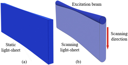
Figure 2. Different forms of light-sheets. (a) In SPIM a laser beam is reshaped to a sheet of light using cylindrical lens. (b) In DSLM, a virtual light-sheet is generated by vertically scanning the excitation beam during the imaging acquisition period of camera.
Download figure:
Standard image High-resolution image2. Fundamentals of LSFM
2.1. Basic working principles of LSFM
There are a large variety of configurations for LSFM; however, their functions revolve around the same principles. In this section, design of a basic LSFM relying on a static unidirectional illumination is discussed. In addition, required optical considerations to design a LSFM based on sample size are presented. For the sake of simplicity, relation between the thickness of light-sheet in illumination arm and the axial resolution in detection arm is neglected. Calculations with more details could be found in [17–19].
Figure 3 shows a simplified version of LSFM system. The system is comprised of two perpendicular independent arms, for illuminating and detecting purposes, and a scanning mechanism. In the illumination arm, a cylindrical lens is utilized to produce a light-sheet. A beam expander, which constitutes of two lenses (L1, and L2), is used to widen laser beam thickness at the entrance aperture of a cylindrical lens. In this way, the effective numerical aperture is increased that allows for producing thinner light-sheets. The clear entrance aperture of the cylindrical lens could be determined using an adjustable slit to regulate the thickness of the light-sheet.
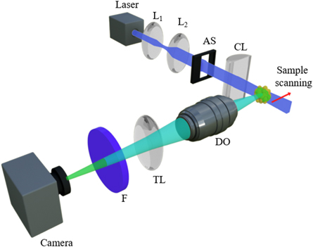
Figure 3. Basic configuration of LSFM. Laser beam expanded by a beam expander constitutes of lenses, L1 and L2. An adjustable slit (AS) sets the clear aperture of a cylindrical lens (CL) and consequently determines the width of LS in confocal region of illumination and detection. The detection arm constitutes of a detection objective (DO), a tube lens (TL), filter (F), and a CCD camera. To obtain a 3D image, sample should be scanned via light-sheet in a step-by-step manner along detection axis to acquire 2D images.
Download figure:
Standard image High-resolution image3D images are formed through stacking of 2D images captured from different layers of sample using the detection arm. Different layers of sample are illuminated via relative displacement of sample and light-sheet. In the simplest case, this could be achieved with placing sample on a stage to move it along the detection axis, perpendicular to the illumination arm.
The detection arm is formed from a regular microscope that includes a detection objective, a tube lens, a filter and a camera.
The lateral resolution of captured images for both fluorescence microscopy and LSFM is affected by the wavelength of the fluorescence emission, λ, the focal length of the detection lens,  and the entrance aperture of the detection lens,
  as follows [20]:

where  is the numerical aperture of detection lens.
Considering the perpendicular configuration of illumination and detection arms, the imaging plane is formed at the confocal region of illumination and detection arms, figure 4. The field of view (FOV) is determined as:

where,  is sensing length of camera,
  shows the number of pixels in the direction of illumination,
  is pixel pitch, and M refers to magnification factor of the imaging system.

Figure 4. Basic considerations for designing a LSFM setup. Region of interest should be smaller than FOV of detecting microscope that is equal to the division of sensing length of camera (L) to magnification of detection system (M), i.e. (FOV=L÷M). Additionally, LS spreads due to intrinsic diffraction of light. Here, the propagation distance in which the width of LS could be considered with minimum changes is approximated by Rayleigh length (ZR). Hence, the suitable width of LS should be determined by considering the sample size.
Download figure:
Standard image High-resolution imageMagnification of imaging system equals to the ratio of focal length of tube lens ( ) to focal length of detection objective (
 ):
):

The main advantage of LSFM is that the need for illumination is only confined to a thin layer of sample at each step of imaging. However, the thickness of illumination beam is wider at both sides of focal plane of cylindrical lens forming a parabolic–like light-sheet. As a result, axial resolution and contrast of recorded images are decreased at regions far from Rayleigh length, figure 4. Rayleigh length is the distance through which the expansion of laser beam could be neglected. The width of a beam expands with a factor of  upon propagation within a Rayleigh length. The Rayleigh length is introduced with the following equation [21]:

where,  and
and  are the beam waist in the focus of illuminating and the Rayleigh length, respectively. A light-sheet with a thickness of
  could be produced using an arrangement of a Gaussian incident beam and a cylindrical lens having a known focal length
  entrance aperture of an adjustable slit (
 ), and the obtained numerical aperture of illumination (
 ), as follows:

Thus, through regulating aperture of cylindrical lens using an adjustable slit, an illumination plane with a desired thickness could be produced. The thickness of the light-sheet should be chosen in which  is greater than or equal to either the FOV of the microscope or sample size.
An example for determining optical features of a LSFM for imaging of samples with different sizes is presented in table 2. The calculations were carried out for a system illuminated by a laser with wavelength of 488 nm via one of two cylindrical lenses having focal length of 5 cm or 10 cm, combined with a fluorescence emission at 520 nm.
Table 2. Designed parameters of LSFM configuration based on sample size. Utilized camera is Hamamatsu - ORCA-Flash 4.0 V2 with pixel size of 6.5 μm and resolution of 2048 × 2048 pixels. The sensor active area for this camera is 13.312 × 13.312 mm2.
| Illumination | Detection | ||||||||
|---|---|---|---|---|---|---|---|---|---|
| Sample | Sample size (μm)/Minimum required FOV | Minimum Rayleigh length (μm) | Beam width (μm) | NAill | Slit width for f = 5 cm (mm) | Slit width for f = 10 cm (mm) | Maximum required magnification | Typical available objective | Lateral resolution (μm) |
| Mouse brain slice | 1000 | 500 | 17.62 | 0.018 | 1.8 | 3.6 | 13 | UPLAN, 10X, NA = 0.3, Olympus | 1.05 |
| Zebrafish fetus brain | 700 | 350 | 14.75 | 0.021 | 2.1 | 4.2 | 19 | UPLAN, 10X, NA = 0.3, Olympus | 1.05 |
| Cultured spheroid | 300 | 150 | 9.65 | 0.032 | 3.2 | 6.4 | 44 | M PLAN 20X, APO, LWD, NA = 0.42 Mitutoyo | 0.7 |
| Cancer cell (metastatic breast cancer) | 13.1 | 6.55 | 2.01 | 0.15 | 15 | 30 | 1000 | M PLAN 50X, APO, LWD, NA = 0.55 | 0.58 |
2.2. 3D image acquisition in LSFM
Displacing the sample along the detection axis is the most straightforward approach to acquire a z-stack, figure 5(a). Since only the sample is moved and the rest of the optics remains fixed, this method is robust and ensures that the light-sheet stays in the detection's focal plane. Although this solution is technically simple, mechanical scanning creates vibrations that might induce imaging artifacts. Furthermore, such translation may be too slow to track some of the fast dynamic processes over the whole sample volume.
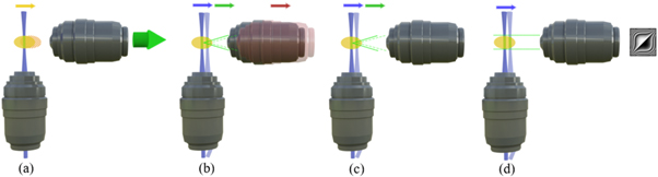
Figure 5. Approaches for constructing volumetric (3D) images in LSFM via (a) moving sample, (b) moving light-sheet and detection objective simultaneously, (c) moving light-sheet and refocusing detection objective employing electrical tunable lens, (d) extending the depth of focus for detection objective by wavefront coding.
Download figure:
Standard image High-resolution imageIn an alternative approach, which seems to be more suitable for fragile samples or samples that need to be kept in a water-like medium, sample is stationary to be scanned by LS. This is possible by either using a motorized stage to move the illumination objective axially, or keep the illumination objective fixed and move the LS using a scanning mirror. Obviously, in these methods, LS should remain in focus plane of the detection objective. In order to satisfy this prerequisite, different solutions have been proposed as listed below:
- A straightforward approach is to use mechanical refocusing, mounting the detection objective to an axially movable stage motor and keeping its relative distance to the illumination objective fixed [22, 23], figure 5(b).
- Without moving a specimen or detection objective, it is possible to achieve flexible volume imaging at much higher speed by utilizing remote focusing. It performs with an electrically tunable lens (ETL) in the detection path between the detection objective and the camera [24], figure 5(c).
- Finally, one could also expand the detection objective's depth of focus by a Wavefront coding technique to cover the entire scan range. The LS can be freely scanned, thus illuminating different planes that will eventually form a volume. This system incorporates a cubic phase mask in the output pupil of the detection objective and results in a slight degradation of lateral resolution [25], figure 5(d).
2.3. LSFM resolution
Optical resolution describes the ability of an imaging system to determine details of an object. Resolution of LSFM could be defined as lateral resolution and axial resolution. Lateral resolution is defined in imaging plane of detecting arm, while axial resolution is described in the perpendicular direction to this plane.
In conventional microscopes, 2D images, as illustrated in the y-z plane of figure 1, are captured by a camera, in which the lateral resolution ( ) is defined for this plane. On the other hand, the axial resolution (
 ) is defined for 3D images along the optical axis of detection arm, as shown along x direction of figure 1.
In an imaging system using a 2D array detector, specification of CCD plays an important role in defining the final imaging properties including FOV and resolution [19]. Ignoring the role of detector, the imaging quality of conventional widefield microscopy is mainly determined by imaging optics.  as lateral and axial intensity distribution of point object in the focal plane of imaging lens is determined by calculating the Fresnel-Kirchhoff integral. Consequently, the axial and lateral resolutions are calculated as below [26]:


where  is the wavelength of the emitted fluorescence,
  is the numerical aperture of detection, 1.78 is a coefficient that is related to the FWHM of the central lobe of the
  function [19],
  and
and  are the lateral and axial resolution in LSFM, respectively. Comparison of equation (6) with equation (7) reveals that the axial resolution
  is poorer than lateral resolution
  since the lateral resolution is inversely proportional to the numerical aperture of the system (
 ), however, the axial resolution is inversely proportional to the
  [27].
[27].
The image formation in LSFM is described as below [28, 29]:

where  is the captured image,
  is the distribution of illumination intensity, c specifies fluorophores distribution, and
  refers to the point spread function of detection system. ∗ refers to convolution operator.
Image of ideal point object in basic LSFM configuration is defined as  Considering the ideal point object placed at origin as
  and uniform illumination across FOV in y-z plane as
  in a simplified approach, the reconstructed image is described as follows:

Thus, the axial resolution in a LSFM differs from conventional widefield microscopes and related to both detection specifications [30] and light-sheet width. Hence, decreasing the width of light-sheet results in improving the detection's axial resolution.
Isotropic resolution means that the resolution in the transversal plane (y–z plane) and that in the longitudinal direction (x direction) are equivalent. Isotropic resolution is an important feature in LSFM to improve image quality. There are several methods to perform isotropic resolution such as rotation of sample [31], replacement of illumination and objective arms [32], multi-directional illumination and detection [33], and use of structured beams [28, 34–36].
2.3.1. LSFM super resolution
Optical resolution of any microscopy method is restricted to diffraction criteria. As LSFM create 3D images, both lateral and axial resolutions are important. The affecting parameters on the optical resolution of LSFM have been discussed in the previous section (equations (6)–(9)).
Many biological and medical fields require subcellular resolution [10] that cannot be achieved using the basic configurations of LSFM. To enhance resolutions higher than Rayleigh criterion for super resolution microscopy, various techniques such as structured illumination microscopy (SIM) [37], stimulated emission depletion (STED) [38–40], and photo-activated localization microscopies (PALM) [41] could be integrated with LSFM.
An approach to enhance lateral resolution of LSFM could be obtained using high NA objectives as detection objectives (DO) (equation (6)). However, this method is not very compatible with conventional configurations of LSFM due to the need for bulky objectives with short working distance. To overcome this issue, use of a single objective with high NA has been proposed [42–44].
Highly inclined and laminated optical sheet microscopy (HILO) was introduced by Tokunaga et al in 2008 [43]. As shown in figure 6(a), in this technique, an objective-type total internal reflection fluorescence microscopy (TIRF) setup was used to direct the incident laser light at angles slightly below critical angle to pass through the sample. The TIRF illumination method is only for the surface area of the sample. By this method, researchers could observe individual molecules on the cell surface. However, the application of TIRF is limited to surfaces because it is using reflection method. By using HILO this issue is eliminated. In this method, the incident beam was refracted at a large angle and obliquely sectioned cell sample near glass surface. The beam waist is affected inversely with the incident angle at the specimen, Then, the beam waist could be well-tuned by changing the incident angle. Once the incident angle moved toward the critical angle, the refracted light intensity increased as its thickness decreased at the critical angle, HILO converged to TIRF with illumination intensity four times higher than the incident light [43]. The advantage of this method is mainly due to use of the illumination beam passing through the center of sample plane that produces a powerful platform for 3D imaging.

Figure 6. Arrangements of super resolution LSFM. (a) HILO, (b) RLSM, (c) LSBM, (d) Lattice LSFM, (e) TILT3D reprinted with permission of [45], and (f) STED-SPIM.
Download figure:
Standard image High-resolution imageIn 2011, Cella Zanacchi et al proposed individual molecule localization-selective plane illumination microscopy (IML-SPIM). They demonstrated three-dimensional (3D) super-resolution live-cell imaging for specimens of 50–150 μm sizes. In their method, SPIM has been coupled with far-field individual molecule localization. The improved signal-to-noise ratio (SNR) of selective plane illumination that allowed for nanometric localization of single molecules in thick scattering specimens without activating or exciting molecules outside the focal plane. They reported 3D super-resolution imaging of cellular spheroids [44]. They were able to continuously image whole sample to achieve 3D imaging with radial and axial resolutions of 63 and 140 nm, respectively.
In 2013, Gebhardt et al developed reflected light-sheet microscopy (RLSM) to reduce out-of-focus fluorescence. In RLSM, a thin light-sheet parallel to the imaging plane and close to the sample surface is generated by reflecting an elliptical laser beam with a small mirror (figure 6(b)). The thin light-sheet allows for an increased signal-to-background noise ratio superior to that in previous illumination schemes and enables imaging of single fluorescent proteins [42].
In 2013, Hu et al suggested light-sheet Bayesian super resolution microscopy (LSBM). They used light-sheet illumination along with a Pellin–Broca prism for super-resolution imaging (figure 6(c)). The prism illuminated a thin slice of the nucleus with high SNR. Their microscopy imaging method was coupled with a Bayesian algorithm to resolve overlapping fluorophores from high-density areas. They showed nanoscopic features of the heterochromatin structure for the first time in both fixed and live human embryonic stem cells. Due to enhanced temporal resolution, dynamic imaging of heterochromatin with a lateral resolution of 50–60 nm on a time scale of 2.3 s was illustrated experimentally [46].
In 2014, Chen et al proposed Lattice LSFM, which utilized a 2D optical lattice to enable higher acquisition speed for studying single molecule dynamics, along with a high resolution for large specimens [45]. Figure 6(d) depicts the schematic of Lattice LSFM. They used a pair of cylindrical lenses in one direction to stretch the input beam, and another pair of lenses in the perpendicular direction for light compression to produce the lattice. A spatial light modulator (SLM) was mounted at the sample plane to create the desired lattice pattern. Lattice LSFM had two-operation regime: the super-resolution regime, which generated 3D images beyond the Rayleigh criterion and the dithered regime for a rapid acquisition of large specimens. Some advantages of the method are high-speed acquisition, capturing larger and more densely fluorescent specimens, single-molecule sensitivity and low photobleaching and phototoxicity.
Gustavsson et al presented tilted light-sheet microscopy with 3D point spread functions (TILT3D) in 2018 (figure 6(e)). TILT3D was designed to image thick cells with features like low-background light, 3D super-localization of single molecules and 3D super-resolution. TILT3D combined a tilted light-sheet illumination strategy with long axial range point spread functions (PSFs). The axial positions of single emitters were encoded in the shape of each single-molecule image rather than in the position or thickness of the light-sheet. Therefore, very thin light-sheet could not be achieved. TILT3D was built upon a standard inverted microscope and had minimal custom parts. A simple and flexible 3D super resolution imaging with tens of nm localization precision throughout thick mammalian cells was reached with TILT3D [47].
Furthermore, the combination of LSFM with STED [38, 39] has been reported to improve the resolution of LSFM. In STED microscopy method, a fluorophore must be employed as an active element during imaging process. The STED method uses stimulated emission to achieve super resolution through depleting unwanted excited fluorophores very locally around the focus center. Friedrich et al combined STED method with SPIM to produce super resolution imaging of model organisms and tissues. They used a modified optical pathway of an original STED method by overlapping the excitation beam with a depleting laser beam with TEM01 mode (figure 6(f)). They significantly enhanced the original advantages of this technique and enabled fast imaging of biological tissues with axial resolution beyond diffraction limits [38].
Recently deep-learning has been employed with LSFM. In this way, deep-learning super-resolution light-sheet add-on microscopy (Deep-SLAM) was developed by Zhao et al in 2020 [48]. They used an add-on that converted a conventional inverted microscope to a LSFM as an efficient and cost-effective approach for super resolution imaging.
Yang et al presented DaXi, that is a single-objective light-sheet microscope using oblique plane illumination. This device benefits from several features including (i) a wide field of view whit high-resolution imaging, (ii) fast volumetric imaging over large volumes, and (iii) high throughput multi-well imaging [49]. Their design could produce a resolution of 450 nm laterally and 2 μm axially over an imaging volume of 3,000 × 800 × 300 μm.
Chen et al integrated structured illumination microscopy (SIM) and light-sheet fluorescence microscopy (LSFM) to enable three-dimensional (3D) imaging using multidirectional structured illumination [50]. The multidirectional structured illumination could be successfully implemented in oblique plane microscopy, a LSFM technique that employs a single objective for excitation and detection in a straightforward manner. They demonstrated isotropic lateral resolution below 150 nm. Compared to traditional SIM systems, lower phototoxicity was achieved with volumetric acquisition speed exceeding 1 Hz.
3. Features of LSFM
3.1. Advantages
The incredible versatility of LSFM allows for its deployment in various biological case studies. LSFM offers several benefits over conventional optical imaging methods. The main advantage of using LSFM in biology is mainly associated with high reduction of photo-toxicity and undesired illumination area owing to the use of selective illumination. Hence, LSFM allows for long-term imaging that is required for studies related to developmental biology. LSFM offers a gentle 3D imaging approach for a wide range of sample sizes from a micron-sized single cells [34, 51, 52] to a centimeter-sized whole organ [11]. It provides an appropriate method for studying many biological processes that occur in a 3D environment such as developing embryos and interactions of neurons. Unlike point scanning procedure in confocal and multiphoton microscopies, the entire plane is illuminated and imaged simultaneously in LSFM. This allows for capturing fast biological processes like brain functional imaging [52]. LSFM offers an opportunity for 3D imaging with isotropic resolution with the same lateral and axial resolutions due to multi-view imaging [11]. Decoupled illumination and detection optical path in LSFM results in a comfortable combination of this method with other microscopy techniques to enhance image quality.
3.2. Constrains
Sample mounting is the most noticeable challenge for user of LSFM. In fact, a standard mounting approach still does not exist for LSFM. A researcher should consider a proper mounting tactic prior to imaging considering the LSFM configuration. Depending on sample size and required conditions for sample mounting, different optical arrangement for LSFM have been developed that will be discussed in section 4. These configurations include a wide variety of designs to hold samples in different sizes including few micrometer-sized specimen in Petri dishes Like light-sheet for Bayesian microscopy (LSBM) or on a conventional glass slide like inverted SPIM (iSPIM [53]), to centimeter-sized sample like a whole mouse brain with ultramicroscopy [11].
The large dimensions of a sample might be considered as another limiting factor. Large samples are quite opaque and scatter light that decrease imaging quality. Large samples should be threated through tissue clearing process prior to imaging [54] for deeper microscopy of opaque structures to obtain more details.
Although, some reports showed the implementation of this method for 3D-imaging based on elastic [55] and inelastic (Raman scattering) scattering [56, 57], LSFM configurations are mainly designed to image fluorescently stained specimens.
4. Configurations of LSFM
Owing to open platform and flexible arrangement of LSFM method, different configurations of LSFM have been realized. LSFM configurations could be categorized based on the number of illumination and detection arms, arrangement of objective lenses, illumination patterns, and sample mounting.
4.1. Geometrical arrangements of illumination and detection arms
Unlike the typical horizontal configuration of two orthogonally mounted objectives in basic SPIM, several illumination arrangements have been reported for LSFM. Depending on application and requirement for sample mounting, these arrangements are different in how and how many objectives are employed. Some of the most well-known methods are briefly reviewed in this section.
In conventional orthogonal arrangement of illumination and detection objectives of LSFM, placement of commercially available high NA objectives is difficult due to their short working distance and bulky design. Moreover, mounting a sample through standard biological method is not possible. Hence, many authors have altered the settlement geometry of objectives. Gebhardt et al [42] suggested a novel configuration of reflected light-sheet microscopy (RLSM) using two high NA objectives in opposite, figure 6(b) Thin light-sheet is brought to imaging plane and close to sample surface by a polished AFM cantilever used as a reflector. As shown in figure 6(c), in light-sheet Bayesian microscopy (LSBM), a prism is placed after illumination objective to redirect light-sheet horizontally onto a sample at the imaging plane of the detection system [58]. Additionally, the Bayesian algorithm effectively resolves sub-diffraction cellular structures. This configuration is more suitable for situations in which the sample needs to be held in Petri dishes.
Objectives arranged in V-shape configuration are well suited for microscopies that require standard sample mounting methods. Inverted or dual-view inverted SPIM (iSPIM\diSPIM) was introduced from Hari Shroff group [32, 53] for single-cell imaging or any samples that need to be mounted on a conventional glass coverslip. Figure 7(a) depicts the schematics of objectives in diSPIM. In this method, two similar objectives are placed above a sample in a V-shape arrangement. Excitation and imaging alternate between these two objectives. Hence, isotropic resolution with equal lateral and axial resolution is achieved in this method.

Figure 7. Arrangements for illumination and detection objectives in LSFM., (a) diSPIM, (b) triple-view acquisition microscopy, (c) OTLS, (d) Diagonally scanned light-sheet microscopy, (e) socSPIM, (f) multiview LSFM, (g) mSPIM, (h) SiMView LSFM, and (i) isoView LSFM.
Download figure:
Standard image High-resolution imageWu et al developed the dual-view light-sheet microscopy and computational method to a simultaneous triple-view acquisition microscopy configuration (figure 7(b)) [59]. Similar to iSPIM, open-top light-sheet (OTLS) microscope takes advantage of V-shape arrangement of illumination and detection arms (in an upside-down direction in comparison to iSPIM) (figure 7(c)) [60–62]. In a developed open-top light-sheet microscope by McGorty et al, a water prism compensates aberrations introduced as a result of 45° orientation of coverglass to illumination and detection path [63]. This configuration is suitable for sample mounting over glass slide, multiwell plates, and microfluidic chips. Alternatively, as depicted in figure 7(d), in a diagonally scanned light-sheet microscopy, V-shape configuration performs by inclining the sample instead of optics [64].
In single-objective LSFM configurations, a thin sheet of illumination light is generated using the same high NA objective that simultaneously collects fluorescence light. The most significant feature of this approach is the possibility of implementation of widely accessible inverted microscopes. Besides, the possibility of using high NA objectives, they are compatible with standard biological sample mounting like slide glass, petri dish, and multiwell plate. Dunsby et al corrected the different axial positions of the image plane by adding another microscope to tilt the imaging plane [65, 66]. Therefore, in-focus imaging of a whole oblique illuminated plane of sample is acquired. They illustrated the application of their adapted oblique plane microscopy for sample mounting in commercially available glass-bottomed 96-well plates [67]. The scanning procedure in this method is effortless. Due to the oblique direction of illumination, the sample horizontally scans through the light-sheet. Hence the optical path is constant during the scanning procedure, and the illuminating plane is always in focus. There is no requirement for using a water chamber or moving the detection objective. Turning the light-sheet to the horizontal plane, i.e. perpendicular to the detection arm, is the other solution to get rid of the difficulty of the oblique imaging plane, figure 7(e). In single-objective cantilever selective plane illumination microscopy (socSPIM), light-sheet is 90° rotated by an AFM tip. The authors demonstrated the application of the setup in the case of mounting the sample on a multiwell plate [68]. Similarly, Light-sheet could also be turned to the horizontal plane in a single objective configuration through the use of a micromirror [69, 70]. Alternatively, the imaging plane is rotated by a small mirror rather than rotating the illumination plane to image a single vertically illuminated plane in a PRISM method [71].
Due to light absorption and scattering, and degradation of the quality of images obtained from the depths of a sample, single view imaging LSFM does not allow for imaging of whole large multicellular organisms. Multiview LSFM (figure 7(f)) [72], in which the sample is rotated, and 3D-stacks are acquired from multiple view angles, could partially enhance the capability of imaging dense large specimens. However, it has some disadvantages including low temporal resolution of imaging of live specimens, induced vibration in the specimen due to mechanical rotation, complex and time-consuming algorithm that needs to merge several stacks from different views to reconstruct a final 3D image, and the extra illumination dose that increase photodamages. In multidirectional selective plane illumination microscopy (mSPIM) [70], absorption and scattering of illuminated light in one direction is compensated by illuminating the sample from opposing direction (figure 7(g)). This solution provides uniform illumination with fewer stripes artifacts across whole FOV. Unlike the ultramicroscopy [11], dual-sided illumination is performed separately - i.e. first from one side and then from the other side - in this method. The scattering of each beam in simultaneous illumination of a sample by two counterpropagating beams results in widening of an overlapped light-sheet in comparison to the width of the light-sheet in single side illumination. However, still the image quality of planes that are closer to the detection objective is better than the deeper planes. A more efficient solution would be to acquire multiple stacks from different views simultaneously and then reconstructing the final 3D image by merging these stacks. As depicted in figure 7(h), in simultaneous multi-view (SiMView) light-sheet fluorescence microscopy implementation, image stacks are acquired by sequentially alternating light-sheet excitation in two opposing scanned light-sheets illumination arms [73]. Two opposite detection objectives gather the fluorescence light. As a result, four complementary views of each depth plane of the specimen are captured in two sequentially illuminations and two simultaneous acquisitions for each one. In state of the art isotropic multiview (isoView) LSFM configurations, four objective lenses are utilized both for illumination and detection to capture stacks of sample from four different views [33]. The arrangement of objectives is depicted in figure 7(i). This method consists of four identical objectives in two orthogonally arranged optical arms, which are simultaneously utilized to illuminate the specimen with a scanned light-sheet and gather the emitted fluorescence of the specimen. To perform volumetric imaging, light-sheets are swept across a specimen, and illuminated planes are kept in focus by translating the detection objectives with piezoelectric stages.
It is worth mentioning that one microscope lens together with a conventional (cylindrical) lens is often sufficient for LSFM, when a low aperture is preferred for illumination. Indeed, in case of making a light sheet thinner (with high NA), an objective lens is employed.
Objective configurations with higher number of illumination arms could enhance the penetration depth of excitation light into dense and larger samples and reduce stripes in a captured image. However, such configurations are usually costly and need precise alignment, which makes these methods not easy to implement especially for whom, are not an expert in optics. These are banning issues, especially for those looking for building their own system based on an open platform of SPIM (OpenSPIM) [74]. Hence, instead of increasing the number of illumination arms, many researchers have proposed various forms of illumination light-sheets to enhance the quality of captured images that are discussed in the following section.
An immersed coupling strategy for middle and end objectives of an oblique light-sheet microscope was achieved by Gong et al to enhance alignment and efficiency of coupling [75]. Their design showed higher performance than the conventional designs that used only air objectives in resolution and light-collection power. They further demonstrated the capacity of this configuration to capture large fields-of-view images in combination with a camera with built-in electronic binning.
Xiong et al proposed a mirror-enhanced scanning LFM (MiSLFM) to achieve high-speed 3D imaging and high axial resolution with a single objective through exploiting the extended depth of field for LFM [76]. They used a tilted mirror that was placed below samples. Superior axial resolution was obtained that enabled acquisition more robust blood cell tracking in zebrafish larvae at high speed.
4.2. Illumination approaches
Some quality features of LSFM images like penetration depth; contrast and present of stripes could be strongly modulated by the method of sample illumination. The penetration of excitation light is affected by intrinsic spreading nature of light, along with absorption and scattering of light once propagating through a sample.
As for the contrast and axial resolution, it is ideal to produce a highly focused light-sheet with minimum thickness; however, the FOV is simultaneously minimized and limited to few micrometers. A conventional LSFM illumination beam has a Gaussian intensity profile with a minimum thickness at its focal point, while the beam diverges at both sides of the focal point. The Rayleigh length is introduced as a distance where beam thickness remains approximately constant. If the specimen is larger than the Rayleigh length, images would be sharply appeared in focus only within the Rayleigh length. Hence, to provide a larger FOV, the width of the illumination beam has to be increased. Consequently, the axial resolution is degraded. Buytaert and Dirckx [77] resolved this problem by stitching columns of single images together, which each image is extended over the Rayleigh length of the illuminating beam. However, this method is time-consuming, and it also does not seem to be suitable for imaging thick samples since the quality of captured images is strongly degraded due to scattering through thick sample. Moreover, interference of various parts of the excitation beam after passing through inhomogeneities or absorbing structures in a sample creates stripes patterns along light propagation path. These artifacts create serious issues for imaging of dense and large specimens. Such stripes are more pronounced in configurations with side illumination. Multiview fusion and multidirectional illumination methods enables to decrease stripe artifacts, however, the adoption of these methods are limited by some disadvantages. The Multiview fusion could not be employed for all samples and sample holding conditions due to the need for rotating sample for imaging from different views. In this way, sophisticated reconstruction algorithms with powerful processing system are required to merge several stacks obtained from different views. In addition, illumination of a sample from different views induces high level of photodamage. The multidirectional illumination method is usually costly and need precise alignment. Hence, these methods could not be employed for all samples. Thus, in the follow section, we will focus only on different approaches of single side illumination with single view imaging for LSFM that are applicable for a wide range of samples.
In the first step to manipulate illumination, static light-sheet with a cylindrical lens could be replaced with scanning light-sheet that forms through scanning a beam in a transverse plane [16]. Thus, the area behind the obstacles is illuminated from different directions and the uniformity of illumination is enhanced. Moreover, the presence of artifacts due to stripes produced by inhomogeneities in a sample is more profound when illumination is spatially coherent, i.e. static light-sheet, in comparison to decrease coherency in scanning light-sheet illumination [78].
Fahrbach et al proposed illumination with Bessel [79, 80] and sectioned Bessel beams [81] as non-diffracting beams. The unique non-diffractive propagation and self-healing properties of these beams are used to overcome scattering and produce larger FOV. Bessel beam's thin core is accompanied by a set of rings producing a large amount of unwanted out-of-focus excitation that results in creation of undesired emissions with subsequent image contrast reduction. It has been attempted to eliminate such unwanted emissions using confocal-line detection [82] and two-photon excitation [26]. In the first method, synchronization between beam position and active line on the camera is crucial. In the second method, the need for using expensive Titanium-Sapphire laser and the possibility of photodamages induced by high power illumination are potential prohibiting issues.
Lattice LSFM, suggested by Betzig Lab [45], is another advanced approach for suppressing the defects of side lobes while benefiting from non-diffractive propagation and self-healing properties of Bessel beam's core. In Lattice LSFM, Bessel's rings could be eliminated through generating a linear array of interfering Bessel beams to make ultra-thin cores that are particularly suitable for imaging single cells. A substantial limitation of Lattice LSFM is owing to the use of only a few quasi-discrete wave-vectors of the ring at a generalized pupil, which considerably reduces beam self-healing property. Therefore, lattice light-sheet could be affected by perturbations produced by a sample that prevent the application of this technology for imaging thick samples.
Wang et al published an article investigating the effect of near-infrared structured illumination on light sheet microscopy [83]. They developed near-infrared II (NIR-II) (1,000 to 1,700 nm) structured-illumination light-sheet microscopy (NIR-II SIM) with ultralong excitation and emission wavelengths of up to ∼1,540 and ∼1,700 nm, respectively. This method allowed for imaging of large volumetric three-dimensional (3D) tissues with deep-axial penetration depths. Furthermore, it diminished background and improved spatial resolution by approximately two folds.
Hung et al combined sensorless adaptive optics (AO), in-situ 3D-PSF calibration, and a single-objective lens inclined light sheet microscope (SOLEIL), termed (AO-SOLEIL), to mitigate deep tissue-induced deteriorations [84]. They applied AO-SOLEIL on several dSTORM samples including brains of adult Drosophila. They observed a 2x improvement in the estimated axial localization precision with respect to widefield without aberration correction while they used synergistic solution.
Dohlakia and his research group proposed the utilization of an Airy beam in LSFM configuration in several publications [85–90]. In comparison to the Bessel beam, Airy beam has less side lobes owing to its asymmetric intensity distribution. Hence, the effect of side lobes on contrast decline is decreased [91].
Akhte et al reported an open-source toolbox for beam shaping by a spatial light modulator (SLM) to be applied within OpenSPIM platform [92]. The toolbox is able to generate several patterns for a wide range of illumination beams, including static and scanning Gaussian beams, Bessel, lattice, and Airy beams.
Producing a robust thin light-sheet over a large FOV is still challenging in LSFM. Recently, some researchers have investigated the role of different illumination beam on image quality
Kafian et al investigated the effect of static, Gaussian, Bessel, and 1D Airy beams and scanning Gaussian, Bessel, and 2D Airy beams on obtained images in terms of contrast, penetration depth, and the presence of stripes artifacts in LSFM, using simulation and experimental tools [91]. Results revealed that due to decreased spatial coherency and self-healing feature, scanning 2D Airy light-sheet is less affected by inhomogeneities of sample and provides deeper penetration length through a sample with higher contrasts and uniform resolution over a wide field-of-view. In addition, it was found that scanning 2D Airy light-sheet is more appropriate choice for illuminating large, i.e. hundreds of microns, and dense samples like tumors.
In a parametric study, Remacha et al suggested helpful guidelines to choose the best suitable illuminating beam and its operating parameters for various applications [93]. They also numerically studied the role of different conventional illumination light-sheets on axial resolution of LSFM. Based on their findings, Gaussian light-sheet is the most appropriate approach for imaging of large, light-sensitive, or thickly labeled samples.
Despite all benefits of using structured beams in illumination, the reduction of contrast in captured images is still remaining as an issue. Besides, the requirement of using costly beam shaping devices and with complex configuration, e.g. extra optical components needed in beam shaping unit, are considered as limiting factors. An alternative for beam manipulation and structuring is pivoting ligh-sheet, especially when combined with multidirectional illumination [94]. This method allows for suppressing stripe artifacts to enhance image quality. Light-sheet direction should be quickly altered using a scanning device, e.g. scanning mirror, within a limited range. Therefore, excitation light is capable of illuminating dark regions behind an obstacle. Pivoting light-sheet approach is not only used for static illumination, but also it could be combined with a scanning illumination method like digital scanned light-sheet microscopy (DSLM) [95]. Sancataldo et al reported some advantages provided by the use of Acousto Optic Deflectors (AODs) instead of a typical scanning mirror for the generation of MHz pivoting light-sheet. They depicted that seven pivoted static light-sheets is indistinguishable from continuously pivoted light-sheet [96]. Nowadays, MEMS devices with affordable prices are available at the market. The integration of LSFM configuration with MEMS-based scanning devices provides a great opportunity for miniaturization of LSFM at lower prices [97]. Itoh et al demonstrated the combination of structured and pivoting illuminations for high quality rapid image acquisition [98] using 1-D spatial light modulator (SLM). In this way, acquired images have less stripe artifacts due to pivoting illumination. Image contrast is increased in comparison with structured illumination.
In overall, designing an easy-to-perform illumination unit at an affordable price to produce high-quality images is still highly demanded. In our opinion, among the above-mentioned LSFM configurations, pivoting static illumination provides the best features in terms of cost, implementation difficulty, and performance. However, for stripes suppression, this solution is not as capable as multidirectional illumination.
Also, the Raleigh length of pivoting static illumination could be enhanced just through applying little changes in the optical setup without increasing the beam waist to preserving the axial resolution [99]. Use of pivoting static illumination to make illumination unit as an add-on for conventional fluorescent microscopes, which are widely available in biological labs, can notably decrease the investment expenses for lab equipment. Usage of MEMS-based scanning devices to build a more compact setup for pivoting static illumination is an enabling approach to decrease the size of illumination unit. An alternative approach for pivoting static illumination is the use of Multiview imaging to reduce stripes artifacts. Additionally, the rotation of sample in Multiview imaging improves the image quality of depth planes that are far away from detection objective. Usually, images from depth planes are degraded by scattering of emission light propagating through the sample to reach the detection objective.
5. Sample mounting approaches in LSFM
Although LSFM provides many unique features for 3D imaging of biological samples, its widespread adoption by communities in biology and medicine has been hampered mainly due to difficulties in sample mounting. Due to LSFM configuration, sample holders should have two orthogonal transparent windows for illumination and detection, (figure 1). Hence, usual straightforward approaches like insertion of a sample on glass slide, or holding it on a Petri dish or multiwell plate are not compatible with the basic horizontal configuration of objectives in LSFM. Besides, samples should be surrounded by a buffer medium with similar refractive index, figure 8. Hanging or sticking of a sample in a medium not only may damage it but also exclude the hanging region from image acquisition (figure 8(a)). To overcome these issues, mounting a sample in a cuvette or tube and fix it with a transparent gel, like agarose, is widely used for LSFM [91] (figure 8(b)).
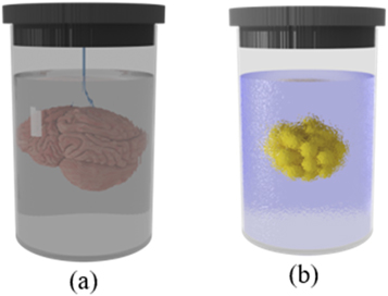
Figure 8. Two examples of sample mounting by (a) hanging in a buffer medium, and (b) fixing in a transparent gel.
Download figure:
Standard image High-resolution imageSeveral innovative optical strategies have been developed that are compatible with standard protocols of sample mounting through turning the horizontal arrangement of two orthogonal objectives, figures 6(b), (c), and 7(d). Generally, single objective and V-shaped configurations are more appropriate for standard sample mounting, figures 7(a), (c), (e), and 6(a). Table 3 summarizes the most noticeable optical implementations of sample mounting.
Table 3. Objectives configuration which are suitable for conventional sample mounting on the slide glass, petri dish, and multiwell.
| Method name | Objective configuration | Sample mounting | Description |
|---|---|---|---|
| iSPIM [53] | V-shaped | Coverslip | The V-shaped orthogonal objective set is designed as an add-on to an inverted microscope, permitting conventional sample mounting |
| diSPIM [32] | V-shaped | Coverslip | The illumination and detection alternates between two orthogonal V-shaped arms |
| OTLS [61] | V-shaped | Glass slide, multiwell plates, and microfluidic chips | The objectives are configured in a V-shaped configuration and in an upside-down direction in comparison to iSPIM/diSPIM |
| DiaSLM [64] | Two orthogonal objectives with sample oriented at 45°, is placed at the focal plane of both excitation and detection objectives | Coverslip | This method is suitable for samples that are adhered to rigid planar substrates. The sample is mounted at 45° relative to optical axis of illumination and detection optics |
| LITE [100] | The illumination arm is tilted between 0° to 90° with respect to detection arm to access short working distance of detection objective | Coverslip | A tilted LS illuminates detection focal plane of high-NA, oil- and water-immersion objective. |
| LSBM [58] | Two oriented objectives | Petri dish | The illumination LS is directed to horizontal imaging plane by a prism. Also, Bayesian algorithm effectively resolves sub-diffraction cellular structures. |
| RLSM [42] | Two opposing inline high NA objectives with small offset | Petri dish, coverslip | LS is reflected in a horizontal plane close to sample surface by AFM cantilever as a disposable micromirror. |
| HILO [43] | Single objective | Coverslip | The highly inclined thin light-sheet illuminated to the sample |
| OPM & ssOPM [67, 101] | Single objective | Glass slide, multi-well, mounting in a petri dish. Microfluidic chips are also possible to use. | The oblique LS illuminates sample. Imaging plane is oriented in accordance with illumination LS by adding a tilted microscope in detection path. |
| socSPIM [68] | Single objective | Glass slide, Petri dish, and multiwell plate | LS is 90° rotated by an AFM tip. |
| PRISM [71] | Single objective | Coverslip | A single vertical plane of sample is illuminated, and a small mirror rotates the imaging plane. This system is easily integrated with a standard combined AFM inverted epifluorescence imaging system. |
| soSPIM [69] | Single objective | Coverslip | LS is rotated to horizontal plane by a 45° micromirror. |
Several attempts have been done to develop sample mounting protocols that are compatible with basic configuration of LSFM. Hedde et al proposed an easy-to-fabricate, customized multi-sample chamber suitable for imaging of a wide variety of sample sizes [102], figure 9(a). Laroche et al designed a versatile sample holder for ZEISS Z1 light-sheet microscope using a 1 ml syringe [103], figure 9(b). The sample holder was used for imaging of a large variety of specimens including Mouse Mesenteric lymph node and midbrain of a P14 male mouse. Pavone et al reported strategies for mounting large samples such as a whole-mouse brain on a tipped plate [104], figure 9(c). Also, They improved image quality by making customized cuvettes made of PDMS as sample holders with water and glycerol solution as inexpensive refractive index matching medium [105].

Figure 9. Methods for sample mounting compatible with basic LSFM configuration. (a) Arrangement of sample chamber, LS, and detection objective for side SPIM setup, reproduced after[102], (b) sliding rod holder designed for ZEISS Z1 light-sheet microscope by Laroche et al, reproduced after [103], (c) sample mounting on tipped plate via (i) directly plunged on top of it, (ii) stitched on a cleared agarose disc, and (iii) inserted in a cleared agarose beaker, reproduced after [104].
Download figure:
Standard image High-resolution imageAlthough various strategies for sample holding have been proposed, the need for more flexible methods is very clear. In fact, users need to have access to user friendly and easy-to-handle methods for sample mounting that satisfy biological requirements and protocols. These methods should enable researchers to perform various protocols such as exchange of medium, adding supplements and drugs, extracting medium, etc with no additional burden. In fact, development of holding methods with such features make LSFM super popular in biological applications for 3D imaging. In this way, microfluidics provide an enabling platform with remarkable capability for creating a new generation of multi-functional sample holders. Moreover, microfluidic systems could provide the opportunity of mounting many samples on a single chip for high-throughput testing and screening of many drug compounds as well as their combinations. In the next section, different roles of microfluidics in sample mounting, sample scanning and illumination approaches for LSFM are reviewed and discussed.
6. Applications of LSFM
High acquisition speed and low photo-toxicity of LSFM enables this method to be employed for imaging of dynamic processes in various applications. LSFM has been utilized in 3D imaging of embryonic development in Zebrafish [16, 106], Drosophila [10, 73, 107], and Caenorhabditis elegans [32]. Moreover, this method is successfully used in multicellular living systems such as spheroids [108] as well as single cells (figure 10) [51, 52] . Additionally, it is a preferred technique for visualizing the structure of large specimens such as fixed and cleared samples [109, 110], such as whole brain and other organs in mouse models [11]. It is also used for imaging of rapid processes like heartbeat and blood flow of Zebrafish models [111, 112]; as well as long-term slow events such as plant growth[113]. However, the most significant application of LSFM in biology is associated with neuroscience, in which it seems to be a unique and irreplaceable imaging method [9, 52, 113]. In the field of neuroscience, obtaining any information on neural interactions is of critical importance for decoding of various aspects of brain functions. Common methods, such as fMRI, MEG, and EEG are not able to provide a sufficient imaging resolution. However, LSFM with a spatial resolution of 200 nm, is a unique technique that could meet requirements of imaging for neuroscience.
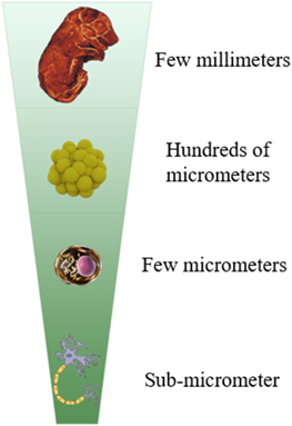
Figure 10. Range of sample size in LSFM.
Download figure:
Standard image High-resolution imageSlide-based 2D microscopy is the gold standard method in pathology for disease diagnostics, patient prognosis and decision making on treatment. This method relies on physical sectioning of samples in which cannot provide 3D visualization of tissues and might induce artifacts to samples during preparation procedure. In addition, slide-based imaging suffers from labor-intensive and time-consuming sample preparation. At this end, there is an extreme need for developing rapid 3D microscopy methods to image intact tissues at high resolution over relatively large areas. In this way, LSFM provides a high-speed non-destructive platform that allows for deep volumetric microscopy with elimination of embedding sample tissues in paraffin to produce glass slides [114]. The LSFM applications are summarized in figure 11.

Figure 11. LSFM applications. Nowadays LSFM have found variety of application in several fields of biological researches. Also, this method has a great potential for clinical applications.
Download figure:
Standard image High-resolution imageJonathon Liu reported the functionality of their developed open-top light-sheet microscope as a fast-imaging device to perform slide-free non-destructive pathologic analysis of large clinical specimens such as prostatectomy samples [60–62, 115]. Compared with conventional microscopy approaches with shallow and fixed depth of focus, their microscopy method provided adjustable (diagonal) field of view that enabled to obtain deep depth of focus for volumetric microscopy of irregular tissue surfaces of excised tissues.
The irregular structures of cancer tumors may not always be detected using standard two-dimensional imaging methods. The application of three-dimensional imaging methods in investigating tumor samples could be very beneficial in revealing the pathological nature of cancer tissues and could provide valuable insights to understand their heterogenicity for designing more accurate treatment approach. Tanaka et al studied proteins and micro-anatomies deep inside of cleared tumor samples using LSFM [116]. They displayed the whole three-dimensional lymphatic microvasculature of formalin-fixed paraffin-embedded (FFPE) tumors of bladder cancer. They could enhance the accuracy of cancer staging through identification of 3D vascular and lymphatic system invasion [116]. Further details on the employment of LSFM in pathology could be found in an article from Poola et al as they reviewed the use of LSFM for human histopathological imaging as a diagnostic tool and compared this method with conventional microscopy approaches [114]. As mentioned earlier, tissue clearing methods are required for 3D imaging of opaque samples. Parra-Damas and Saura reported various brain tissue clearing techniques that could be used for LSFM and other microscopy methods for circuits-to-synapses brain imaging to investigate the cellular and molecular basis of neurodegenerative diseases [117]. Figure 12 illustrates some examples for applications of LSFM in biology. For more details, Stelzer et al published a comprehensive and remarkable review paper that fully covered the applications of LSFM in biology [118].
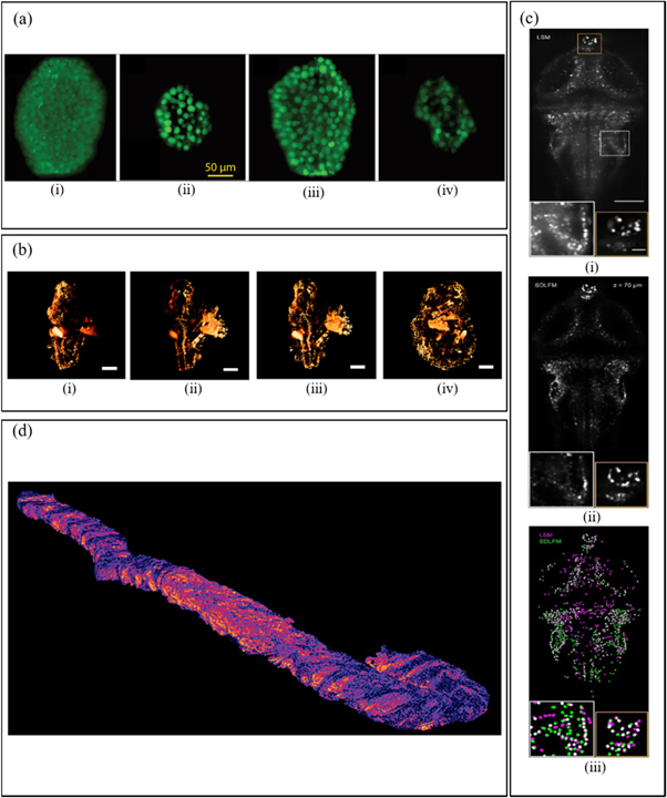
Figure 12. (a) Captured 3D view (i) and cross-sectional LSFM images of a mammosphere, from three depths of 20, 120 and 220 μm (ii-vi), respectively, reprinted with permission from [91]. (b) Imaging of mouse embryo. (i) one side. (ii) opposite side. (iii-iv) combined from both sides. Scale bars are 500 μm, reprinted with permission from [119]. (c) (i) Temporal MIPs of light-sheet microscopy (LSM) images. (ii) the corresponding sparse decomposition Light-field microscopy (SDLFM) volume sections. (iii) and segmentation results. Scale bar, 100 μm, reprinted with permission from [120]. (d) Open-top light-sheet microscopy (OTLS) images from 3D pathology data, reprinted with permission from [121].
Download figure:
Standard image High-resolution image7. LSFM with microfluidic solutions
The combination of light-sheet illumination with microfluidics has resulted in the development of various microsystems for label-free or labeled cytometry for particle sizing and senescent cell identification [122], imaging of cells and spheroids cultured in microfluidic chips [123], and imaging of embryos for developmental biology purposes [124] . Integration of optics with microfluidics allows for making optical components, i.e., optical lenses, using unique spatial fluid characteristics at microscale [125]. In recent years, attempts have been directed to employ optofluidic principles for high-resolution 2-D and 3-D imaging.
Peng Fei et al proposed a stage-free self-scanning LSFM system based on an optofluidic chip in which the scanning process was achieved as water-in-oil plugs passed through chip's imaging region illuminated by a laser sheet. In this optofluidic in-channel flow scanning method; samples could be loaded in a moving liquid plug that eliminates the need for using complicated mechanical scanning. The chip was made using soft lithography in PDMS. The chip had three inlets for introducing sample flow (fluorescent microparticles), carrier (FC-40 oil) flow, and reagent flow using syringe pumps. The chip had one outlet to recycle microparticle-containing plugs. This configuration was used as a plugin with a conventional microscope [126] (figure 13(a)).
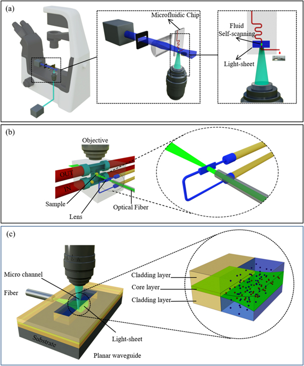
Figure 13. (a) Stage-free self-scanning on-chip LSFM system from Peng Fei group, reproduced after [126]. The scanning process was performed by passing water-in-oil droplet which contains sample through light-sheet. (b) Optofluidic tunable cylindrical lens for generating light-sheet, as combined with in-channel flow scanning, reproduced after [123]. (c) Mass-manufacturable microfluidic chip with integrated light-sheet illumination by coupling the laser light from output of an optical fiber to an on-chip waveguide, reproduced after [127]. The generated light-sheet penetrates into a microchannel with flowing samples.
Download figure:
Standard image High-resolution imagePaie et al developed an optofluidic tunable cylindrical lens for generating light-sheet [123] that was combined with the in-channel flow scanning developed by Peng Fei [126] for LSFM, (figure 13(b)). The light-sheet has a tunable focal length that allows for adjusting its working distance and thickness [123]. An optofluidic cylindrical lens was formed in a liquid channel with an aspherical cross section.
The channel is fabricated in glass using femtosecond laser micromachining method and poste-treated with hydrofluoric acid (HF) solution. The microchannel was filled with a high refractive index liquid. When the refractive index of the flowing liquid alters, the focal length of the optofluidic cylindrical lens also changes consequently. For sample scanning an H-shape microchannel was fabricated in the same glass slide that contains the cylindrical lens. The channel had a square cross section with width of 500 μm to allow for moving of 300 μm tissue spheroids without interference with channel walls. Importantly, the channel was designed with H shape with two same inlets and outlet to hold the sample organoids in the centerline of the channel with no transversal movement and rotation during optical scanning.
The channel is fabricated in glass using femtosecond laser micromachining method and poste-treated with hydrofluoric acid (HF) solution. The microchannel was filled with a high refractive index liquid. When the refractive index of the flowing liquid alters, the focal length of the optofluidic cylindrical lens also changes consequently. For sample scanning an H-shape microchannel was fabricated in the same glass slide that contains the cylindrical lens. The channel had a square cross section with width of 500 μm to allow for moving of 300 μm tissue spheroids without interference with channel walls. Importantly, the channel was designed with H shape with two same inlets and outlet to hold the sample organoids in the centerline of the channel with no transversal movement and rotation during optical scanning.
Considering even more compact integration of optical setup in a microfluidic chip, Deschout et al reported a mass-manufacturable microfluidic chip with integrated light-sheet illumination [127]. As depicted in figure 13(c), light-sheet is generated by coupling the laser light from the output of an optical fiber to an on-chip waveguide that creates a light sheet. The sheet could penetrate into a microchannel with flowing samples. This configuration was used for single particle tracking of membrane vesicles in cell culture medium and in interstitial fluid collected from primary human breast tumors for size and concentration determinations. Thus, no light-sheet scanning was performed for this cytometry configuration.
The planar waveguide constituted of a 5 um spin-coated core layer made of pure SU-8 sandwiched between two 25 um spin coated cladding layers made of SU-8 mixed with 6% epoxy resin.
The combination of microfluidic with LSFM method can have a great impact on clinical cytometry. For cytometry applications, use of flow focusing to produce a single column stream of cells is necessary. In case of using light-sheet for cytometry purposes, this requirement is eliminated due to fast imaging acquisition and large imaging FOV across a flow channel. Thus, LSFM method provides a platform for high-throughput cytometry [128, 129]. A high-speed on-chip light-sheet excitation flow cytometer is presented by Miura et al, which can work at the speed of 1 m s−1 [130]. Their mirror-embedded microfluidic chip is especially compatible with single objective LSFM configuration without the need for any external reflective elements such as a micromirror, prism, or AFM tip.
While the use of glass in the forms of glass slide and square capillaries for sample mounting has been realized [122, 123, 131], different polymers such as PDMS, PMMA, EFP have been also explored for the fabrication of microfluidic chips, table 4. PDMS, a thermoset, is the most common material for microfluidics that could be shaped through soft-lithography process using pre-fabricated master mold. PDMS based chips could be assembled and bonded to glass or PDMS slabs via oxygen plasma method. PDMS is gas permeable. Thus, embedded channels within PDMS could exchange gas with their surrounding environment for some applications that requires oxygen and CO2 exchange during cell culture. In addition, proper optical features of PDMS has allowed for conducting wide field (visible) and fluorescence microcopies in microfluidic devices.
Table 4. Common polymers for fabrication of microfluidic chips and their optical properties.
| Name | Reflect index | Optical transparency (UV) | Optical transparency (Vis) | Fluorescence properties | Transmission[132] | Haze[132] |
|---|---|---|---|---|---|---|
| PDMS [Polydimethylsiloxane] | 1.43 [133] | Good [134] >220 nm [135] | Excellent [134] (Transmittance at 830 nm (IR): 93%) | Weak fluorescence emission (absorption peak at 403 nm) | — | — |
| PMMA [Poly(methyl methacrylate)] [Good UV resistance] | 1.4893 [136] | Good [134] >340 nm [135] | Excellent [134] | 89%–92% | 0.1%–2.6% | |
| PET [Polyethylene terephthalate] [Fair UV resistance] | 1.5750 [136] | Good [137] | Good [137] | 78%–92.1% | 0.2%–5.1% | |
| PEEK [Polyether ether ketone] [Good UV resistance] | 1.66 [138] | Poor [137] | Poor [137] | Strongly fluorescent material in wavelength range of 350–550 nm | — | — |
| PTFE [Polytetrafluoroethylene] [Good UV resistance] | 1.3500 [136] | Excellent, Optically transparent [137, 139] [high transmittance (91%) at 355 nm] [140] | Optically transparent [137, 139] (not absorptive) but opaque | — | — | |
| FEP [Fluorinated ethylene propylene] [Good UV resistance] | 1.344 [138] | Good Optically transparent [137, 139] [high transmittance (94%) at 355 nm] [140] | Excellent [137, 139] | 92% | 0.7% | |
| PC [Polycarbonate] [Fair UV resistance] | 1.5860 [136] | Poor [134] >360 nm [135] | Excellent [134] [Transmittance at 830 nm (IR): 9%] | 86%–91% | 0.2%–2.7% | |
| PS [Polystyrene] [Good UV resistance] | 1.5894 [136] | Poor [134] >300 nm [135] | Excellent [134] | — | — | |
| CBC [CYCLIC BLOCK COPOLYMERS] | 1.507 [141] | Excellent [134] | Excellent [134] | — | — | |
| COP [Cyclic olefin polymer] | 1.509–1.53 [141] | Excellent [134] | Excellent [134] | — | — | |
| COC [Cyclic olefin copolymer] | 1.53 [141] | Excellent [134] >360 nm [135] | Excellent [134] | 91% | 3% |
Thermoplastics such as PMMA, PC, COC, etc are also widely used for the fabrication of microfluidic devices mainly using rapid prototyping methods including micromilling and laser micromachining methods without any need to have pre-fabricated molds [142–144] . Thermoplastics, in general, have higher mechanical properties and higher chemical resilience compared to PDMS. Thermoplastic devices could be assembled through thermal fusion bonding without any particular chemical pretreatment . In general, thermoplastics provide suitable optical transparency.
High transparency, matched refractive index with cultured medium, compatibility with cell culture, machining properties, and mechanical strength are the main considerations for material selection. Concerning the presence of a water chamber in most LSFM, any refractive index mismatch between culture medium and channel material induces distortion of illuminating light-sheet. This also has detrimental effects on the quality of captured images, which could not be eliminated even by water immersion objective in the detection arm. Hence, the choice of material with a refractive index close to culture medium is significantly important. In general, fluorinated thermoplastics have closer refractive index to water in comparison with PDMS, PMMA and PC, as shown in table 4.
Fluorinated thermoplastics such as Teflon and Fluorinated Ethylene Propylene (FEP) have close refractive index to water. The first one is opaque, therefore, not suitable for LSFM configuration. FEP seems to be a well-suited material for fabricating microfluidic chips in LSFM configuration [145]. On the other hand, chips can be fabricated from popular materials such as PMMA and PDMS; and refractive index matched solution like the combination of water and glycerol could be used [146]. Uneven side surfaces of microfluid chips that induce light perturbations once it passes through the chip could be addressed using V-shape or single objective configurations. Moreover, such issues could be mitigated during manufacturing procedures [126] or through inserting the chip in a solution with close refractive index [147, 148] in basic configurations.
The implementation of microfluidic chips, which are benefited from all the exclusive features mentioned above, as a plugin for conventional optical microscope, is a promising approach for a broad range of clinical applications.
8. Add-on units for integration with conventional microscopes
In recent years, companies have introduced some commercialized standalone light-sheet fluorescence microscopes into market as listed in Supplementary table 1. However, the price is banning issue. The wise solution for this issue is to implement LSFM as an add-on for available optical microscopes at labs. Use of optical microscopes, as detection arm for LSFM configuration, have been reported by various research groups [43, 65–68, 149]. However, such optical arrangement does not provide sufficient flexibility to be employed as a separate mountable add-on for conventional microscopes. To convert a conventional optical microscope into a LSFM, additional alterations in microscopes structure are required. Having a mountable light-sheet illumination unit, as a plug and play add-on, for optical microscope allows for easy conversion of a 2D microscope into 3D microscope with minimum cost.
To this end, majority of attempts on developing mountable add-ons have been performed by Peng Fei and Schnechenburger groups.
Peng Fei et al developed a compact plane illumination plugin (PIP) device as an add-on with approximate dimensions of 15 × 5 × 5 cm3 [150] (figure 14(a)). The device has an optional extra illumination unit for dual-sided illumination. Also, it was built from low-cost and widely available components, however, 3D scanning is not motorized for the PIP and needs to be performed manually with a 1D translation stage. In the next step, they combined an off-axis scanning scheme and a sub-voxel-resolving (SVR) algorithm to increase the resolution of captured images [31, 48], and their approach was named as Sub-voxel-resolving Light-sheet Add-on Microscopy (SLAM) [151], figures 14(b) and (c). They implemented their illumination-scanning add-on system on top of an Olympus IX73 inverted microscope. Various studies were performed including imaging C. elegans larva, visualization of beating heart and vessel system of zebrafish and a cleared mouse brain. They illustrated the 10-fold enhancement in resolution in comparison to the host microscope and fast 3D imaging up to three volumes per second.
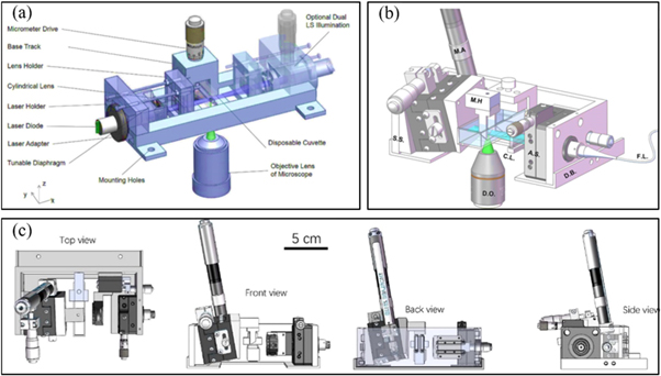
Figure 14. (a) Schematic of the Plane Illumination Plugin (PIP). The frame of PIP is fabricated by 3D printing. It is constituted of a laser diode module, a cylindrical lens to generate light-sheet, a disposable cuvette as sample holder, and a micrometer for vertically displacing a sample. In PIP, generated light-sheet propagates horizontally through the sample, reprinted with permission from [150]. (b) Schematic of sub-voxel-resolving light-sheet add-on microscopy (SLAM). It is constituted of device base (D.B.), collimated fiber coupled laser (F.L.), a cylindrical lens (C.L.), an adjustable slit (A.S.), a magnetic holder (M.H.), and a sloped stage (S.S.) driven by a motorized actuator (M.A). D.O. refers to detection objective, reprinted with permission from [48]. (c) Top, front, back and side views of the SLAM device.
Download figure:
Standard image High-resolution imageVery recently, they have developed an algorithm to improve image contrast and axial resolution of SLAM using deep learning approach [48].
In 2012, Schnechenburger et al used a mountable add-on optical system for sample illumination to convert an inverted microscope to a light-sheet microscope. To illuminate samples, hold inside a microcapillary, a mirror was used to redirect light into samples. The plugin design allowed for easy tuning of the illumination arrangements using adjustable screws [152] (figure 15(a)). In 2015, the device was modified to perform observations from different views using rotation of a sample [152] (figure 15(b)). In 2016, the designed was further improved and miniaturized through using fiber optic, instead of Galilei telescope, to transmit light from laser source into sample holder [153] (figure 15(c)).
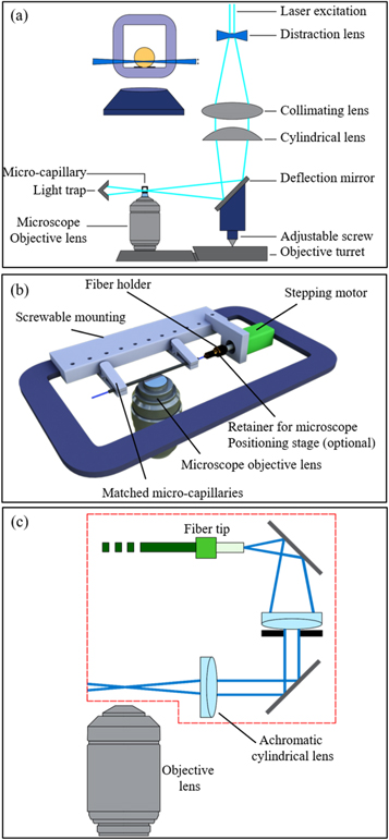
Figure 15. (a) LSFM illuminator add-on for an inverse microscope. The collimated laser beam is expanded by a Galilei telescope and focused by a cylindrical lens to generate illuminating light-sheet. This plane is deflected onto the sample by a 90°mirror. The deflection mirror and cylindrical lens are coupled to the objective turret of the microscope by an adjustable screw, while other components are fixed on the base plate of the microscope stage. Light-sheet and the detection objective are vertically moved together and all illuminated planes are in focus, reproduced after [152]. (b) Sample holder for rotation of samples applicable to x-y stage of microscope, reproduced after [154]. (c) A more compact illumination unit, in comparison to (a), fabricated by removing the Galilei beam expander. Light-sheet is generated by employing collimating lens, aperture, and cylindrical lens in optical path, reproduced after [153].
Download figure:
Standard image High-resolution imageVarious industrial attempts have been initiated to develop devices to convert commercial microscopes in light-sheet microscopes. Leica® has recently developed an add-on to convert a confocal microscope (Model TCS SP8) into a light-sheet instrument. The design of Leica is completely different from the methods reviewed in this article. In the reported methods, the illumination system and the detection system were usually perpendicular to each other, but in the method developed by Leica®, a TwinFlect mirror was used to illuminate the sample and allows the integration of the illumination and detection beam path into vertical axis of Leica TCS SP8 without compromising confocal functionality, figure 16(a).

Figure 16. (a) Schematics for an add-on to convert a confocal microscope (Leica TCS SP8) to a LSFM. Horizontal illumination plane is generated with 90° rotating the scanning vertically illuminated beam by TwinFlect mirror. (b) Carin, L-SPI Single Plane Illuminator as an add-on for conventional microscope to generate a sheet of light, reprinted with permission from [155]. (c) The combination of low photodamage of LSFM (i) with high-NA objectives of confocal microscopy (ii) was employed in commercially available illuminator add-on known as Mizar illuminator add-on (iii) and (iv). Light-sheet is tilted by rotating the cylindrical lens. (i) to (iii) is reproduced after [100], and (iv) is reprinted with permission from [156].
Download figure:
Standard image High-resolution image
Also, Cairn Research® company based in UK has developed a new add-on L-shaped Single Plane Illuminator (L-SPI) with capability of installing on any macro- or microscope to perform live-cell imaging with ultra-low phototoxicity. It uses single-mode fiber to direct the laser beam to the Cairn plane illuminator unit (figure 16(b)).
Mizartilt is another add-on for generating light-sheet, which produces tilted light-sheet illumination to inverted microscopes. However, thin and fixed thickness of generated light-sheet onxly designed for imaging of small samples such as simple cell [100] (figure 16(c)).
9. Image processing and visualization of 3D stack
Dealing with large sized captured 3D stacks of LSFM is a big challenge. The common softwares among LSFM community for this goal are Imaris, Amira, and Volocity as commercial softwares, and ImageJ and its several plugins, Vaa3D, BioImageXD, and Icy as open-source platforms. Lots of image processing actions and practical applications could be performed by these softwares. Moreover, the deconvolution is very critical in LSFM image preparation. Deconvolution in image processing is image restoration to remove certain degradations from image e.g., to remove blurring from a photograph due to the wrong focus or with camera shaking during the image acquisition. The types of degradations that deconvolution can reverse are described by a mathematical process called convolution. Since deconvolution is a process that tries to find the state of an image before some degradation occurred, starting from the degraded image, deconvolution can be categorized as a solution to an inverse problem and the mathematics of inverse problems are relevant to understanding and devising deconvolution algorithms [157–159].
In LSFM, samples usually keep in the water chamber to overcome the refractive index mismatch between the sample and the surrounding medium. However, when the costly water immersion detection objectives are not accessible, aberrations from inhomogeneity in the detection path degrade the image quality. Deconvolving the captured 3D stack with measured point spread function (PSF) may mitigate the degradation of image quality by aberration. Estimation of the PSF by more precise algorithms, like the Gibson-Lanni model [160], or performing the blind deconvolution [161] are other solutions when direct measurement of PSF is not possible. In addition, illuminating a sample with structured light or thick illuminating plane generate the fluorescence emissions from several depth therefore deteriorate the contrast of images captured in this way. Such defects resolved by deconvolution of the captured images with the illumination and detection PSF. There are already many software packages for deconvolution purposes as listed in Supplementary table 2.
9.1. Stripes suppression
In general, any absorptive or inhomogeneous along illumination path induces stripes artifacts. Such artifacts are serious prohibiting issues to use LSFM for imaging of dense and large specimens.
Stripes are especially pronounced due to sample's unidirectional illumination from side view. Stripes artifacts can be mitigated or completely removed via extra illumination from other sides of a sample or through image processing methods. The first approach includes multiview imaging [72] or multidirectional illumination solutions [11, 33, 94], as discussed in section 4: Configurations of LSFM . Regarding the second approach, several destriping methods that some of them were initially developed for other microscopy methods, could be also employed for LSFM, as explained below.
Wu et al 's proposed a method to mitigate both identical and different stripes at different layers of a sample 3D stack [162] for Optical Coherence Tomography Angiography (OCTA) images.
Pollatou et al proposed an automatic stripe removing method for stitched biological images based on finding the location of stripes and modeling their background [163]. An algorithm, called Variational Stationary Noise Remover (VSNR) was developed as a free Fiji plugin [164]. The authors depicted the application of their method with images acquired using LSFM.
Pavone et al presented the optical and post-processing methods for removing strips in a review article [165].
In addition to microscopic images, stripe artifact is a severe limiting issue in remote sensing systems. Several studies provided solutions for this problem [166, 167], which could be also utilized for LSFM images with minor modifications. As an example, Chang et al estimated complex stripes distribution by wavelet-based deep convolutional neural network method for destriping remote sensing systems' images [168]. They improve the performance of their algorithm by simultaneously modeling the stripe and image components.
10. Conclusions and future directions
The unique features of LSFM has been employed in various applications where high temporal volumetric microscopy is required including developmental biology, 3D cell culture, imaging for pathology, and microfluidic cytometry within the last 15 years. Despite all advantages of LSFM, this method of imaging has not gained widespread popularity that is mainly associated with unstandardized and difficult sample mounting and working procedure requiring a level of optical expertise. In addition, high cost of LSFM platforms is another affecting issue against their widespread popularity. Considering this fact that LSFM is still in early stage of its development, development of novel designs of LSFM for easy sample mounting and standardized optical adjustment at affordable prices is a critical need.
A practical solution to address such design considerations revolves around the development of an add-on to convert a conventional 2D microscopy into a LSFM in a cost effective fashion. This goal is highly achievable since LSFM has a relatively simple optical configuration and provides a flexible optical platform compared to other volumetric microscopy approaches.
Moreover, in vitro investigation of tissues in conditions close to their real biological or physiologically relevant conditions to examine effects of various stimuli and micro environmental properties on live samples are highly demanded in modern biology. In this way, integration of LSFM with microfluidic 3D cell culture and organs on-chip technology provide results in the creation of an enabling platform for conducting high-throughput in vitro testing including drug testing and disease modeling. Importantly, on-chip flow manipulations and sequencing using microfluidic actutors allows for conducting complex cellular studies with high spatial and temporal control over various chemical and physical stimuli and conditions like drug compositions, oxygen tension, matrix stiffness and mechanical forces, as well as co-culture of cells in multiple microchambers. In addition, precise control of flow conditions in microfluidics could inspire further developments of microfluidic approaches for optical scanning of samples in microchannels instead of using a mechanical scanner. This may result in the development of lab-on chip devices for diagnostics.
Pathology is another field that can highly take advantage of LSFM for precise analysis of tissue samples for more accurate diagnostics, and design of more efficacious treatment approaches. Importantly, high speed imaging of discected samples in operation room could open a new avenue for surgeons for precise tumor remov. For all such applications, it is of utmost importance to develop light sheet microscopes that requires minimum technical expertise for easy sample mounting and rapid device preparation and adjustment.
Considering the required image processing for LSFM stacks, estimating/measuring the detection PSF, for performing deconvolution, is not possible in all cases. Hence, the deconvolution of images with blind deconvolution algorithms are more suitable especially for the cases of multi-immersion medium in which the estimation of detection PSF is very difficult. It is worth mentioning that the coupling of the acquired 3D stacks by LSFM with image processing and machine learning algorithms to provide automatic image classification between different types of human cells and performing this method in clinical applications is a great opportunity for producing analyzer commercially devices.
Acknowledgments
SAMS would like the financial support from National Institute for Medical Research Development (NIMAD) under grant number of 988175 for this research. In addition, SAMS appreciate technical notes provided by Clinical Research Unit of Ghaem Hospital to enhance the applications of the LSFM.
Data availability statement
This is a review article. The data that support the findings of this study are available upon reasonable request from the authors.
Supplementary data (0.1 MB DOCX)