


Abstract
Component development for operation in a large-scale fusion device requires thorough testing and qualification for the intended operational conditions. In particular environments are necessary which are comparable to the real operation conditions, allowing at the same time for in situ/in vacuo diagnostics and flexible operation, even beyond design limits during the testing. Various electron and neutral particle devices provide the capabilities for high heat load tests, suited for material samples and components from lab-scale dimensions up to full-size parts, containing toxic materials like beryllium, and being activated by neutron irradiation. To simulate the conditions specific to a fusion plasma both at the first wall and in the divertor of fusion devices, linear plasma devices allow for a test of erosion and hydrogen isotope recycling behavior under well-defined and controlled conditions. Finally, the complex conditions in a fusion device (including the effects caused by magnetic fields) are exploited for component and material tests by exposing test mock-ups or material samples to a fusion plasma by manipulator systems. They allow for easy exchange of test pieces in a tokamak or stellarator device, without opening the vessel. Such a chain of test devices and qualification procedures is required for the development of plasma-facing components which then can be successfully operated in future fusion power devices. The various available as well as newly planned devices and test stands, together with their specific capabilities, are presented in this manuscript. Results from experimental programs on test facilities illustrate their significance for the qualification of plasma-facing materials and components. An extended set of references provides access to the current status of material and component testing capabilities in the international fusion programs.
Export citation and abstract BibTeX RIS

Original content from this work may be used under the terms of the Creative Commons Attribution 3.0 licence. Any further distribution of this work must maintain attribution to the author(s) and the title of the work, journal citation and DOI.
This article was updated on 26 August 2021 to correct the copyright line.
1. Material and component testing requirements
Plasma-wall interactions (PWI) and the associated huge particle and heat fluxes to plasma-facing components will decisively determine the availability and thus the economy of a fusion reactor because of their impact on the lifetime of the first wall (erosion and deposition of plasma-facing materials, damage of plasma-facing components) and on safety (tritium retention and dust production).
In view of plasma-wall interactions in future fusion devices such as ITER and a DEMO reactor, new challenges have to be met:
- Extended operational regimes with respect to particle and heat flux densities onto plasma-facing components, both steady-state and transient
- Extended operational time, very long pulse lengths towards steady-state operation, leading to a total particle fluence and total number of heat load cycles onto first wall components by far not accessible in current fusion devices, to huge amounts of eroded wall material, and to material fatigue due to high cycle numbers
- The presence of tritium as fuel gas, emphasizing the importance of fuel retention and governing the selection of first wall materials
- Neutron irradiation of plasma-facing components, resulting in substantial material damage up to 150 displacements per atom during the lifetime of a power reactor, with enormous impact on material properties and thus on both the quantitative extent and the qualitative character of plasma-material interaction processes and the performance of components
- Synergistic effects of the above mentioned operational conditions in fusion reactors (high heat and particle loads and neutron damage)
Important PWI and material issues are related to short time scales of physical processes and can be investigated in devices with short pulse length such as power exhaust, erosion behavior and the subsequent transport of eroded wall material into the plasma edge. However, major PWI and material issues become significant on long time scales and high cycle numbers: The build-up of deposited layers and their stability, the evolution of the surface morphology of plasma-facing components, the accumulation of dust, the build-up of fuel inventory in plasma-facing components, fatigue effects associated with a large number of transients and the accumulation of neutron damage with its impact on PWI processes and thermo-mechanical properties of first wall materials.
Current confinement experiments do not cover the operational conditions expected in a future fusion reactor and needed to investigate the PWI and material issues related to long time scales. In terms of plasma and neutron fluence, there is a big step from ITER to a future DEMO reactor as illustrated in table 1. Starting from the JET tokamak, typical operational parameters are listed for ITER and the current layout of DEMO within the EU fusion programme. The ratio of heating power over the major radius P/R is used as a measure of the steady-state power exhaust [1], the stored energy over major radius W/R for the impact of transients such as edge localized modes (ELMs) [2], the operational time per year tyear (and duty cycle) to account for the fluence effect, and the averaged integrated neutron power flux density at the outer first wall  to illustrate the expected neutron damage.
Table 1. Scaling of operational parameters relevant for power exhaust and plasma-wall interactions from JET to ITER and DEMO.
| JET [3] | ITER [4] | DEMO [5] | |
|---|---|---|---|
P/R

| 11 | 25 | 50 − 70 |
W/R

| 3 | 60 | 100 − 150 |
tyear

|

|

| 1–
|
| (duty cycle) | ( ) ) | ( ) ) | (0.3–0.6) |

| ∼0 | ∼0.3 | ∼5–10 |

|
As a consequence of the gaps—in particular the huge step from ITER to DEMO—shown in Table 1, dedicated plasma-wall interaction and heat load test facilities have to supplement confinement devices in order to investigate and test first wall materials and components for future fusion devices. For these testing programs, all relevant processes of plasma-wall interaction and inside the bulk of the loaded materials have to be understood to obtain predictive capabilities. This requires on the one hand accurately defined testing (exposure) conditions as can be provided in test facilities rather than in confinement devices. On the other hand good access to material samples and components by diagnostics (most preferably in situ diagnostics) is required. Such access can be realized in test devices more easily because of their simpler geometry. In a second step, the technical functionality of components has to be developed and understood, based on the assessment of processes of plasma-wall interaction and in loaded materials mentioned above. Such a procedure requires flexible options for assembly of target samples and prototype components. Finally, procurement and qualification testing has to be performed, in particular high heat flux testing, to mitigate the operational risk in a reactor. For efficient and realistic testing, high throughput and reactor relevant testing conditions—including the capability to handle neutron pre-damaged material samples and components—are required.
To meet the testing requirements listed above, various kinds of testing devices have been developed and are in use. This manuscript provides a thorough review of the facilities presently available and to be taken into operation in the near future. Section 2 focuses on devices for high heat flux testing of materials and components, both under steady state and transient loads. These tests are mainly performed by high power electron and ion beam facilities to investigate the thermo-mechanical behavior of materials and components. Section 3 describes linear plasma devices which are used to investigate the erosion of plasma-facing materials and fuel retention at high fluence. Synergistic effects of both heat and plasma loads are investigated in linear plasma devices which are equipped with high power lasers to mimic transient heat loads. To include the impact of neutron-induced material damage into the assessment of plasma-facing materials, linear plasma devices can be operated in radiation-controlled areas. Section 4 gives an overview of the specific effects of neutron damage on the lifetime of plasma-facing components and tritium retention and introduces existing and planned testing facilities in order to address these specific issues 5 .
Finally, section 5 gives an overview of PWI programs in confinement devices with special emphasis on experiments done with the help of manipulator systems. Theses installations provide the integrated loading scenario of a fusion device, since all dedicated testing facilities mentioned so far fall short in view of two important aspects of plasma-wall interactions. First, the impact of the specific magnetic field topology in confinement devices, which governs the actual load distribution on plasma-facing components and processes like local deposition and material migration with large significance for the lifetime of plasma-facing components. Second, the impact of PWI processes on the global plasma performance, giving rise to a non-linear coupling between plasma and wall. While studies on plasma-wall interactions are conducted in all major confinement devices, dedicated manipulator systems are installed in a number of tokamaks and stellarators to bridge the gap between confinement devices and dedicated PWI test facilities in terms of flexibility of target handling.
2. Facilities for high heat flux testing
The plasma-facing components in the future fusion devices ITER and DEMO will be subjected to intense thermal loads and long discharge durations, which will put high demands on their heat transfer capabilities. Using water or helium as a coolant, this will require an efficient coolant channel design to enable safe operation.
The ITER design is based on a nominal heat load of 10 MW m−2 for steady state operation and on a reduced number of off-normal slow transients up to 20 MW m−2 [6]. The nominal heat load can be separated into a stationary contribution and a contribution arising from fast transients, as shown schematically in figure 1. The latter are the so-called edge localised modes (ELMs), which naturally occur in H-mode operation. They are triggered by strong gradients in the plasma edge. In large fusion devices ELMs occur with a frequency of the order of a few Hz [7]. For ITER the assumed power deposition rise time is 220–260 μs followed by a slower decay time of 500–1200 μs [8]. A typical ELM duration as defined by the temperature rise time of 500 μs is given in [9].
As natural ELMs in ITER would carry heat loads going beyond the acceptable level for the tungsten divertor, the frequency needs to be increased by a factor of typically 30 by ELM pacing techniques, which corresponds to a proportional decrease of ELM energy content, or complete or partial suppression of ELMs by other techniques has to be applied [7].
An energy density of 0.4–1.2 MJ m−2 to avoid melting of tungsten in ITER ELMs is given in [10]. More recent publications define the load limit by the onset of crack formation. For 1 ms pulses [11] gives a limit of 0.3 GW m−2 for bulk tungsten.
The superposition of the thermomechanical stress caused by the stationary loading with the additional transient peaks generated by ELMs, as illustrated in figure 1, requires separate experimental investigation of materials and components under such conditions.
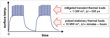
Figure 1. Schematic representation of the surface temperature during two successive plasma discharges in ITER or DEMO. The temperature profile is characterized by the pulsed stationary thermal load and the fast transient ELM-loads which generate an additional temperature increase during the H-mode phase.
Download figure:
Standard image High-resolution imageThe aim of high heat flux test facilities is the investigation of the thermo-mechanical behavior of newly developed materials and components complementary to the study of plasma-wall interaction performed in fusion experiments or linear plasma devices as described in section 3. All these types of facilities are indispensable to develop reliable plasma facing components for long term operation. This section exemplifies high heat flux test facilities which are mainly used for the testing of plasma-facing materials and components for typical divertor and first wall applications.
A number of different test facilities are utilized routinely to simulate the quasi-stationary heat fluxes to first wall or divertor components. In these tests electron beams, ion or neutral beams or plasma streams are directed towards the actively cooled test components to determine the load limits, i.e. the maximum applicable heat loads during plasma operation, and to quantify the critical heat fluxes, where burn-out effects are initiated by the collapse of the heat transfer to the coolant. Another important feature which determines the maximum allowable thermal loads during long term plasma exposure of PFCs is the fatigue resistance which is characterized by the maximum number of applied pulses at a predetermined heat flux level.
High heat flux performance tests on ITER or DEMO specific PFCs are not limited to thermal fatigue or thermal shock induced experiments under mitigated ELMs, but must also include analyses on thermally induced microstructural changes, namely grain growth and recrystallization or re-solidification effects. In addition, it must be investigated whether the material degradation is increased by synergistic effects when different loading conditions are combined, e.g. steady state loads and simultaneous exposure to extreme transients need to be evaluated carefully. Such tests also have to include hydrogen and helium induced effects (see section 4) as well as material and component degradation by energetic neutrons to allow reliable predictions on the lifetime of PFCs. Besides discussing general features of the interaction of particle beams with materials, this section gives an introduction to high heat flux testing and test facilities. An overview of major high heat flux test facilities is given. Instead of discussing all types of facilities in detail, the section focusses on electron beam and neutral beam facilities, which are then further exemplified by more detailed descriptions of the electron beam facility JUDITH [12, 13] and the neutral beam facility GLADIS [14]. Finally, the influence of simultaneous exposure to combinations of loading conditions and the resulting synergistic effects are discussed.
2.1. Fundamentals of energetic particle loads to solid materials
In this section the specific properties of electron and neutral beam facilities with particle energies in the range of 10–150 keV are described. The interaction of energetic particles with a solid target can be separated into two different processes: energy loss and deflection of the particle [15]. The energy loss per unit length depends on the particle energy E and is usually called the 'stopping power' S(E). It can be subdivided into inelastic transfer of kinetic energy of the projectile into the electronic system of the target and elastic collisions transferring kinetic energy from the projectile into centre-of-mass motion of target atoms. In ion beam literature these are termed 'electronic stopping' and 'nuclear stopping', respectively; see for instance [16].
If we compare electrons with ions or neutrals in the energy range of tens of keV then electronic stopping is the dominating average energy loss mechanism for both, light and heavy particles. Energy loss by bremsstrahlung is only relevant at very high particle energies. For instance a 100 keV electron impinging onto a tungsten target converts only about 1% of its initial kinetic energy into bremsstrahlung [17]. For lighter target materials this fraction is even less.
When comparing electron beams with ion or neutral beams of the same energy with respect to penetration depth, it turns out that electrons cover a much longer distance in the solid than heavier ions and thus reach a larger depth before they come to rest. Therefore the depth into which energy is deposited is larger in the case of an electron beam than in the case of an ion beam. Figure 2 shows a comparison of the penetration depth of electrons, hydrogen and helium atoms, respectively, in tungsten and carbon as examples for high and low Z materials. The data for hydrogen and helium are projected ranges according to the PSTAR and ASTAR databases of NIST, see [17]. The data for electrons are projected ranges calculated as average depths from electron deposition profiles computed with the Monte-Carlo code CASINO 2.48 [18]. For a rough estimation of the electron penetration depth empirical analytic approximations are available for various energy ranges, see for example [19].

Figure 2. Comparison of projected ranges of electrons with those of H and He particles in carbon ( g cm−3) and tungsten (
 g cm−3) as examples for light and heavy target materials. The H and He data are projected ranges from NIST databases, see [17]. The data for electrons are projected ranges calculated from deposition profiles computed with the code CASINO, see text.
Download figure:
Standard image High-resolution imageWhen comparing the deflection properties of electron and ion beams of the same energy impinging in a solid, the electrons experience much more deflection from scattering events per unit length than ions. This leads to the effect of backscattering. The backscattering coefficient is not strongly dependent on the primary electron beam energy. However it depends on the atomic number of the target material. For heavy target species the fraction of backscattered electrons leaving the target surface can reach nearly 50% [20]. In such a case most of the backscattered electrons have energies close to the primary energy. This means that also the amount of reflected energy is of a similar percentage. For ions or neutrals in the range of 20 keV the corresponding energy reflection coefficient ranges up to a few percent for light particles impinging on heavy target species, see e.g. [21].
2.2. High heat flux testing and test facilities
To determine the heat transfer efficiencies and the low-cycle fatigue performance of water cooled PFCs, today electron beam and neutral beam test facilities are the most common test devices which are characterized by a relatively large flexibility in terms of loaded area and achievable power density. In addition, these test devices can also be employed for the simulation of intense transients. Figure 3 shows in a schematic representation the various types of high heat flux devices and their capability for performing stationary and/or transient heat loading. Electron beam and neutral beam facilities will be described in further detail in this section. Pulsed lasers, typically Nd:YAG lasers in the near-infrared wavelength region are used to apply short transient loads with high powers to small surface areas [22]. Quasi stationary plasma accelerators (QSPA) [23] can provide intense plasma pulses with a pulse duration of several hundred μs to simulate ELM-like thermal loads on relatively large surface areas. In these devices also melt motion and splashing of melt layers under the impact of fusion relevant plasma pressure can be investigated in detail. In contrast to the pulsed plasma devices such as QSPA, linear plasma streams (see section 3) are in general used to generate steady state plasmas to study plasma-wall interaction (PWI) phenomena under high fluence plasma exposure. Today superimposed transient heat loads can be generated by a fast increase of the input power in the plasma source which is achieved by a capacitor bank system coupled in parallel with the DC power supply. Using this technology, ELM-relevant conditions have been achieved in hydrogen and helium plasmas [24].
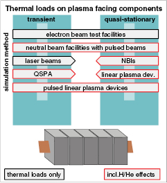
Figure 3. Classification of different high heat flux test facilities and their capability to simulate stationary and/or transient thermal loads. The red frames indicate test devices which also allow the investigation of synergistic effects triggered by hydrogen or helium ion irradiation.
Download figure:
Standard image High-resolution imageDue to the large demand for testing capacities—both for steady-state and also for transient thermal loads—a large number of powerful test facilities are in operation in different laboratories worldwide. Table 2 shows a list with major high heat flux test devices. The specific features and the available test capacities are in good agreement with the research programs of the involved national research units and domestic agencies. In addition, particular test requirements such as materials screening, developments of new component designs and improved joining technologies, qualification of finalized design options before serial production and the procurement testing of full scale first wall or divertor components after industrial manufacturing had strong impact on the design of these test devices and on the installed diagnostics. Typically used sample diagnostics are:
- CCD and IR cameras for visual monitoring;
- one and two-colour infra-red pyrometers for local measurements of surface temperature;
- cooling water calorimetry.
Table 2. Compilation of major electron, hydrogen or helium beam driven high heat flux test facilities worldwide.
| HHF test facility | Particle type | Particle energy (keV) | Beam power (kW) | Max. loaded area (m2) | Power density (GW m−2) | Remarks | Institute ITER partner |
|---|---|---|---|---|---|---|---|
| Tsefey-M | e− | 40 | 200 | 1.0 | 1.0 | Scanned beam,  –20 mm beryllium compatible hot water and hot He cooling loop –20 mm beryllium compatible hot water and hot He cooling loop | Efremov RF [25] |
| IDTF | e− | 60 | 800 | 2.25 | 1.0 | Scanned beam,  –50 mm hot (ITER-like) water cooling loop –50 mm hot (ITER-like) water cooling loop | Efremov RF [26] |

| e− | 120 30–60 |

|

| 10 | Irradiated samples hot coolant loop, Be compatible | FZJ EU [12, 13] |
| FE 200 | e− | 200 | 200 | 1.0 | 60 | Scanned beam,  –3 mm hot coolant loop –3 mm hot coolant loop | CEA EU |
| JEBIS | e− | 100 | 400 | 0.18 | 2 | Beam sweeping  1–2 mm 1–2 mm | JAEA JA [27] |
| EB 1200 | e− | 40 | 1200 | 0.27 | 10 | Scanned beam,  –12 mm hot coolant loop, Be compatible (temporarily shut down) –12 mm hot coolant loop, Be compatible (temporarily shut down) | SNLA US [28] |
| KoHLT-EB | e− | 60 | 300 | 0.35 | 10 | Scanned beam,  mm hot water and He cooling loop mm hot water and He cooling loop | KAERI KO [29] |
| HHFTF | e− | 45 | 200 | 0.27 | 1.2 @ 80 kW 0.7 @ 200 kW | hot water loops; scanned beam  mm @ 80 kW and mm @ 80 kW and  mm @ 200 kW mm @ 200 kW | IPR IN [30] |
| EMS 60 | e− | 150 | 60 | 0.01 | 10 | He coolant loop | SWIP CN [31] |
| EMS 400 | e− | 60 | 400 | 0.8 | 10 | Hot water coolant loop | SWIP CN |
| HELCZA | e− | 55 | 800 | 1.8 | 40 | ITER first wall full-scale beryllium components (under construction) | CVR EU [32] |
| DATS | H+ , He+ | 50 | 1500 | 0.1 | 0.06 | 2 ion sources à 0.75 MW  mm mm | JAEA JA [27] |
| GLADIS | H+ , He+ | 50 | 2200 | 0.3 | 0.05 | 2 ion sources à 1.1 MW  mm, hot coolant loop mm, hot coolant loop | IPP EU [14] |
Some of these test facilities also have been accredited to test problematic materials such as beryllium armour, tritium contaminated and/or neutron irradiated plasma facing components.
2.2.1. Electron beam facilities.
Electron beam devices in the high voltage range (typically 100–200 keV) in general use a well-focused beam with diameters in the mm range. Medium voltage test facilities (typically 30–60 keV) use beams with about 5 mm in diameter. The resulting heat fluxes of ∼1–60 GWm−2 qualify this type of facilities for ELM-like loading tests. Scanning of the beam is necessary for loading with lower heat fluxes. The scanning mode depends on the installed control system.
The beam diameter can easily double when operated in regimes with high extracted currents. On the other hand, increasing vacuum pressures during the testing process can result in a remarkable self-focusing of the electron beam. Hence, a pressure control system can minimize fluctuations in the beam diameter and thus in the applied power density.
To simulate ITER- or DEMO-relevant thermal transients the required heat fluxes are generated by focusing the electron beams to diameters in a range from approx. 1 to 5 mm (depending on the beam extraction system and on the acceleration voltage). Homogeneous heat flux profiles in the loaded area are achieved by fast digital or analogous beam scanning; these methods help to eliminate local hot spots and also allow the modification of the temporal pulse shape from rectangular to Gaussian or triangularly shaped beam pulses [33].
Different power supply modes can be applied in cathodic electron beam generators to produce intense beams with different pulse duration: the so-called 'transformer mode' allows the extraction of long pulse (hundreds of ms) or steady state beam pulses, while very short events ( ms) are generated in a 'capacitor mode'. However, fast switching between these two modes or periodical changes of the beam current is not feasible with the existing test devices. Hence temporal variations of the applied power densities can only be achieved by a sophisticated beam scanning pattern with variations of the dwell time and/or the lateral displacement of the e-beam.
Example of the design of an electron beam facility.
For-schungszentrum Jülich GmbH operates two electron beam test stands, the Juelich Divertor Test facility JUDITH1 and 2 with different beam characteristics. JUDITH1 is equipped with a high voltage power supply unit which is capable of generating rather well focussed electron beams with energies up to 150 keV; here the maximum beam power is 60 kW. The second test facility JUDITH2 (figure 4) accelerates electrons to 30–60 keV and can deposit up to 200 kW on relatively large surface areas (<0.25 m2). Flat power density distributions can be achieved by beam scanning using analogous or digital scanning modes; in this configuration the two test devices form ideal test beds to evaluate the heat removal efficiency and the thermal fatigue performance of plasma facing components. Heat removal can be provided by high pressure water coolant loops (<40 bar).
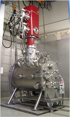
Figure 4. Electron beam test facility JUDITH2 with a maximum beam power of 200 kW.
Download figure:
Standard image High-resolution imageTo simulate transient thermal loads such as ELMs, plasma disruptions or VDEs, the beam scanning is confined to relatively small surface areas (typically less than 1 cm2). These thermal shock tests can be repeated with frequencies up to 25 Hz, thus allowing ELM simulation experiments with pulse numbers up to 1 million events on water cooled or pre-heated test samples. In addition, synergistic load tests with steady-state and transient thermal loads can be performed in a wide parameter range.
Both test facilities are installed in a controlled area and are licensed to operate with toxic and radioactive or tritium containing materials. This is an essential feature for heat load tests on beryllium armoured plasma facing components for ITER or other confinement experiments. To enable the safe operation, the test bed JUDITH1 has also been installed inside a hot cell. It is operated routinely with neutron irradiated test samples.
2.2.2. Neutral beam facilities.
Neutral beam test devices [14, 34, 35] in general feature relatively high beam powers in the MW-range and large beam diameters with a Gaussian-like beam profile and beam diameters in the order of 70–200 mm FWHM. Pulse lengths up to 45 s can be applied. Also transient events such as ELM-like pulsed loads up to 120 MW m−2 can be realized with short pulses of ms duration and repetition rates of 100 Hz.
The beam generation is based on the acceleration of hydrogen or helium ions. An ion source generates ions, which are extracted from the source plasma and accelerated up to 10–100 keV. In the case of hydrogen the source delivers a mixture of atomic and molecular ions which are subsequently neutralised by charge exchange processes. Hence the extracted beam consists not only of full energy neutral atoms, but also of atoms with one-half and one-third energy. Because of the large beam diameter and the high power density, neutral beam systems are excellent tools for investigations of large-scale material samples and components. Therefore beam scanning is not required. Neutral beams generate homogeneous heating due to the nearly complete absorption of the beam power at the surface of the tested material. Furthermore, the low particle penetration depth of only several tens of nm into solids generates a fusion-relevant surface heating, see figure 2. Therefore neutral beam facilities apply well-defined heat loads independent of the loaded surface material.
Example of the design of a neutral beam facility.
The neutral beam facility GLADIS (Garching Large Divertor Sample test facility) at IPP Garching was designed to test large actively water-cooled components as well as small material samples [14]. The water-cooled vacuum test chamber (1.5 m in diameter, 3.2 m in length) is equipped with two 1.1 MW ion sources from the former W7-AS stellarator, partially visible in the background of figure 5. An upgrade of the source cooling allows a variation of the pulse length from 1 ms up to 45 s. The two sources are operated independently of each other; this allows the superposition of different thermal and particle loading and gives a unique capability for operation with H, He or mixed H/He neutral beams and thermal loads. Both ion sources are inclined at 8° to the horizontal axis of the facility. The preferred position of the target is at the 3 m focal length in axial direction at the intersection of the beams. To simplify the design of the facility, no magnetic ion removal system with deflection magnets, ion dumps and cryo-pumps was installed.

Figure 5. GLADIS neutral beam facility. The vacuum lock for target exchange is visible in front of the vessel.
Download figure:
Standard image High-resolution imageA vacuum lock and translation system for the test samples is installed to reduce the pumping down time after target exchange to 20 min. The system allows the positioning of the samples within an accuracy of ±0.1 mm. In addition to the above mentioned standard diagnostics the following diagnostics are installed for measurements of the thermal response and the spatial and temporal temperature distributions of tested components.
- up to 40 thermocouples for instrumentation of mock-ups;
- up to 20 additional sensors, e.g. pressure drop, strain gauges, mass spectrometer;
- calorimetry consisting of PT100 sensors and calibrated cooling water flow meters;
- mass spectroscopy to study the outgassing during loading.
2.3. Synergisms of combined loading conditions
In general different types of thermal loads, plasma-wall interaction and neutron-induced effects are treated separately (by different groups and/or in different laboratories). To account for synergistic effects an all-encompassing approach is required.
2.3.1. Stationary and transient thermal loads.
Quasi-stationary and ELM-like transient thermal loads occur simultaneously during H-mode plasma discharges in tokamaks. Therefore, the interaction between these two load types has to be investigated experimentally to check for synergistic effects. Long ranging thermal stress fields during stationary loads can cause growth of thermal shock cracks initiated by edge localized modes. In addition, the prevailing temperature fields have strong impact on the material performance: e.g. W armour in a position close to the water-cooled heat sink shows on the one hand brittle damage below the ductile-brittle-transition-temperature (DBTT); on the other hand, very high temperatures, as they occur during the peaks of combined transient and stationary loads, can initiate recrystallization processes which cause the material to lose its ductility.
Therefore, load tests which combine both load types are indispensable for a realistic experimental simulation of the predominant loading scenarios. These tests can be performed in dedicated high heat flux test devices as shown in figure 2, namely in e-beam devices with flexible beam scanning modes [36] or in neutral beam devices with additional pulsed ion source operation, which allow to increase the surface heat loads periodically. As described above, the neutral beam facility GLADIS, for instance, can be operated with two independently controlled ion sources. This allows to use e.g. one source for stationary loading and pulsed operation of the other to apply an additional periodic heat load. Linear plasma devices at FOM DIFFER are equipped with additional capacitors and fast switches which allow to generate additional peaked plasma discharges with predetermined power densities and repetition rates [24]. In a dedicated high heat flux test campaign parts of these testing options have been utilized to evaluate the performance of actively cooled divertor target modules for ITER under combined stationary and ELM-like thermal loads [36].
2.3.2. Influence of hydrogen and helium.
Another important issue is the synergistic loading of plasma-facing components with plasma particles and high heat fluxes. The implantation of hydrogen isotopes into metallic surfaces has, among others, strong impact on the embrittlement of the hydrogen infiltrated surface. High concentrations of implanted hydrogen will also trigger the formation of small hydrogen bubbles in surface near regions which may also affect the overlying metallic surface by so-called blistering processes. The thickness of the hydrogen-affected surface layer strongly depends on the energy of the incident ions; the migration into deeper layers mainly depends on the prevailing temperature. Another important feature are pre-existing or load-initiated trap sites in the hydrogen-affected surface layer.
Besides hydrogen and in particular the fusion-relevant isotopes deuterium and tritium, also helium, the fusion product, also has strong impact on the material performance. Helium will be implanted similar to hydrogen. Helium implantation into tungsten at high surface temperatures (T > 1000 K) results in the formation of tendril-like, porous tungsten extrusions (see [37] and references therein).
In GLADIS, operation with pure Helium beams as well as with fusion-relevant H/He mixtures has been performed on actively cooled tungsten components. The erosion behavior and the retention of hydrogen and helium in the material have been investigated, see [38, 39]. The simultaneous application of heat and particle fluxes, which are both in an ITER- or DEMO-relevant order of magnitude, however, goes beyond the scope of this section.
2.3.3. Degradation by neutrons.
The continuous bombardment of all plasma-facing components in DT-burning fusion devices by energetic neutrons is another serious damaging mechanism which will have strong impact on the high heat flux performance of plasma-facing materials and components. First of all, high fluxes of fast neutrons (up to fluences of approx. 1 dpa in ITER and up to tens of dpa in DEMO) will deteriorate the thermal conductivity, which has strong impact on the heat removal efficiency of the wall armour. In addition, neutron irradiation will also change the plasticity of metallic wall materials, i.e. the ductile-to-brittle transition temperature (DBTT) will be increased and thus restrict the operation window in which a ductile response of the PFCs can be guaranteed. Hence, neutron irradiation experiments have to be performed on small-scale actively cooled mock-ups which will then undergo a sophisticated post irradiation examination (PIE) process. Among others, this also includes the performance of steady state and transient high heat flux tests under fusion relevant operation conditions.
In summary, plasma-facing components in future fusion reactors have to withstand exceptionally harsh conditions: extreme stationary and transient heat loads, intense plasma exposure and neutron induced degradation. To evaluate the load limits of commercially available and newly developed plasma-facing materials, to design, manufacture, and qualify actively cooled wall components, and to achieve the safe operation of the full plasma-exposed wall under these severe operation conditions, high heat flux experiments are indispensable. This implies a sophisticated testing procedure which is based on a careful calibration of the HHF test facilities and the diagnostics.
Besides simulation experiments with quasi-stationary heat loads which are primarily based on the evaluation of the fatigue performance of the joint between plasma-facing material and the heat sink, also transient events to quantify the thermal shock response of plasma exposed surfaces are in the focus of extensive research programs. Today, electron beam and ion beam driven test devices are most customary. Together with versatile linear plasma devices, this new generation of test devices also has the capability to perform synergistic load tests, i.e. the combination of steady-state and transient thermal loads simultaneously. In this context also synergistic experiments which include hydrogen/helium plasma bombardment and the exposure of small scale PFCs to reactor relevant fluences of energetic neutrons pose further challenges to the HHF test equipment.
3. Linear plasma devices: simulating plasma-facing conditions
Plasma-wall interaction (PWI) is one of the most critical issues with respect to the performance, safety and availability of ITER and future fusion reactors [40, 41]. The plasma-wall conditions in a tokamak reactor are defined by high particle and heat fluxes to the wall, both in steady-state and during transient events, i.e. edge-localised modes (ELMs) and disruptions. The wall will be eroded under the plasma bombardment, limiting the lifetime of the wall components and affecting the purity of the fusion plasma. The eroded materials can be transported and deposited at a different location inside the plasma chamber, particularly on remote wall components. Here, a significant amount of radioactive tritium can be stored through co-deposition.
The presence of impurities will influence the PWI processes by both physical and chemical interactions. Tungsten, beryllium, helium and divertor cooling species (argon, neon or nitrogen) will be present as impurities in the ITER plasma [40, 41].
High-energy neutrons from the fusion reactions can lead to a change of structural and thermo-mechanical properties of the wall materials. In ITER, the expected fluence of neutrons is rather low, corresponding to ∼1 dpa (displacement per atom), and is not considered as a threat. In contrast, in a future full-scale reactor during its total operation time the dose will exceed 100 dpa, having significant consequences for the wall performance.
These PWI processes can lead to reduced availability of ITER and future reactors through the shortened lifetime of the wall components and through limitations originating from safety regulations, including restrictions on the allowable amount of tritium retention and dust production. These issues need urgently to be addressed, both in experiments and by modelling, to improve the predictions and to optimize the solutions for ITER and beyond.
Modern large-scale tokamaks are close to ITER with respect to many relevant discharge parameters, such as operational scenarios and magnetic field configurations. However, there are still significant gaps for some crucial PWI factors, like ion fluxes and fluences at the strike point, temperature of the plasma-facing components, performance of neutron damaged materials and elemental composition of plasma and the wall.
Linear plasma devices (LPDs) offer the possibility of closing these research gaps at moderate costs. The versatility of LPDs to produce stable, steady-state multi-species plasmas is unique. The material of choice can be exposed to pre-selected conditions to simulate the environment of the reactor plasma boundary. During any development program there exists a series of tests necessary to advance the technology readiness level. Some of these tests can be performed in dedicated platforms and after filtering the results of many such dedicated tests, the most promising candidates can advance to testing in multiple effect platforms. LPDs are one such multiple effect testing platform. LPDs combine the impacts of several single effect facilities (such as ion beam sputtering, high heat flux, gaseous atom diffusion in the material, plasma effects, etc) into a single testing platform to begin to address synergistic affects not observable in single effect facilities. The ability to investigate the role of neutron-activated materials within reasonable timeframes and costs, and the achievement of extremely high plasma fluences in short times, are two such examples of areas where LPDs will greatly speed technology development for DEMO. However, LPDs are but one step in the staircase of technology development and results from material testing in LPDs must proceed into more complicated and expensive integral testing in toroidal confinement facilities. LPDs are not an end in and of themselves, but have proven to be exceptionally valuable in helping develop technology for today's confinement facilities and will no doubt contribute in the necessary technology development for DEMO.
There are many facets of the reactor-relevant PWI research. They range from rather plasma specific (e.g. impurity transport in a tokamak) to material specific (e.g. development of new materials) and wall component specific (e.g. testing of wall components in high heat flux facilities). The focus of this contribution is on plasma-material interaction (PMI) studies, i.e. what happens to materials during the reactor-relevant plasma exposure. This contribution provides an overview on the PMI-oriented research in LPDs, including select recent scientific highlights, and discusses the prospects of LPDs in contributing to the solution of the wall material problems for fusion reactors. This section extends and updates an earlier overview of the topic [42].
The PMI research in LPDs and tokamaks is complimentary. LPDs have, however, some advantages with respect to present tokamaks:
- In present LPDs ion fluences relevant to the ITER divertor can be reached, while in most present tokamaks the typical fluence is one or two orders of magnitude lower;
- The studies in LPDs are very flexible and include good control and reproducibility of exposure parameters. Independent parameter variations in a multi-dimensional parameter space are possible. LPDs have generally better accessibility, higher reliability and better access for in situ sample analyses than tokamaks;
- The PMI research in LPDs is more cost efficient than in tokamaks. Both the costs of construction and exploitation are significantly higher for tokamaks.
This section is structured as follows: the general set-up of a PMI dedicated linear plasma device, methods of plasma production, typical plasma parameters and frequently used diagnostics are described in section 3.1 followed by examples of experimental PMI studies in LPDs, associated modelling activities and prospects of the PMI research in section 3.2.
3.1. Linear plasma devices as material test facilities
3.1.1. General set-up of linear plasma device and parameters of material exposure.
There are a variety of set-ups of LPDs including different types of plasma sources, magnetic field configurations, vacuum systems and material target manipulators. However, the general set-up for a PMI experiment in LPD is rather simple. LPD typically consists of a cylindrical vacuum chamber enclosed with magnetic field coils in a linear configuration (figure 6). Most LPDs deploy water-cooled copper coils capable of producing a steady state B field of ∼0.1 T. The vacuum chamber is usually subdivided into several regions. In the source region, a plasma column with a diameter of ∼1–10 cm is formed, then proceeding along the B field through the buffer region towards the target exposure region. Typically, only ∼1–10% of working gas is converted to plasma. The buffer and exposure regions can be separated by a vacuum diaphragm to allow for the differential pumping of the gas introduced into the plasma source. The necessity of the differential pumping is given by the different requirements for the optimal gas pressure and composition in the plasma source and at the target. The ionization degree in the target exposure region can be increased up to ≈50% if differential pumping is applied. In the exposure region, the plasma parameters are monitored, e.g. by a Langmuir probe or by a Thomson scattering diagnostic. The region of the plasma-target interaction is usually observed by various spectroscopic methods, e.g. measuring the amount of sputtered target material. The material samples are usually loaded using a vacuum lock system in the sample exchange region and introduced into the exposure region by a sample manipulator equipped with a linear drive. The samples are typically of ∼1 cm size so that the surface is exposed uniformly in a plasma column of several cm width.
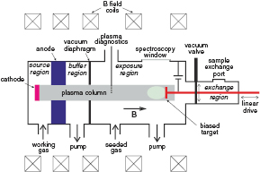
Figure 6. Schematic view of a linear plasma device for PMI studies.
Download figure:
Standard image High-resolution imageTable 3 summarizes operational parameters of a selection of LPDs, the scientific programmes of which are focused on PMI studies, in comparison with the conditions expected at the divertor target in ITER. Further PMI dedicated LPDs include DIONISOS (MIT, USA) [58, 59], DiPS (Hanyang University, Republic of Korea) [60], GyM (IFP-CNR, Italy) [61], LENTA (Kurchatov Institute, Russia) [62], Linear Plasma Generator (JAEA, Japan) [63], MAGPIE (Australian National University) [64], MAP-II (Tsukuba University, Japan) [65], MP2 (National Fusion Research Institute, Republic of Korea) [60], NAGDIS-I (Nagoya University, Japan) [66], PS-DIBA (Nagoya University, Japan) [67], TPD-Sheet IV (Tokai University, Japan) [68] and STEP (Beihang University, China [69]). Obviously, the target exposure parameters in LPDs cannot completely match the boundary plasma conditions in a tokamak, i.e. the complexity of the magnetic field configuration of a divertor. However, the PMI relevant parameters of material exposure in present LPDs come quite close to the conditions expected in the ITER divertor. Even if the particle density and, therefore, the flux in most LPDs is about one order of magnitude smaller than at the strike point in ITER, it can be compensated for the total dose by a long, several hours, exposure, gaining a fluence corresponding to about one ITER pulse. The incident ion energy can be varied by applying a negative target biasing. The material sample temperature can be controlled by adjusting the heating by plasma and external heating and cooling of the target. The plasma species composition can be changed using an external gas seeding. The heat pulses produced by transient events such as ELMs in tokamaks can be simulated in LPDs by high power laser pulses [22, 70–72] or by pulsed plasma produced by a pulsed operation of the plasma source [73] or by a plasma gun [74]. Such transient producing systems coupled to LPDs permits the examination of sequential versus simultaneous exposures and allows identification of synergistic effects [72, 75].
Table 3. Main and PMI relevant parameters of linear plasma devices actively contributing to the worldwide PMI research. Parameters of the ITER divertor are given for comparison. Details on the nuclear parameters of TPE are given in section 4.2.1.
| PISCES-B (UCSD, USA) | PISCES-A (UCSD, USA) / TPE (INL, USA) | NAGDIS-II (Nagoya University, Japan) | PSI-2 (FZJ, Germany) | Pilot-PSI (FOM-DIFFER, The Netherlands) | Magnum-PSI (FOM-DIFFER, The Netherlands) to date/projected | ITER divertor for  scenario scenario | |
|---|---|---|---|---|---|---|---|
| Discharge type | Reflex arc | Reflex arc | Cusp arc | Arc with cylindrical cathode | Cascaded arc | Cascaded arc | Tokamak |
| Magnetic field (T) | 0.04 | 0.1 | 0.25 | 0.1 | 0.4–1.6 | 0.43–1.73 / 3 | 5 |
| Electron density (m−3) | 1016–1019 | 1016–1019 | up to 1020 | 1016–1019 | up to 1021 | 1019–1021 | 1020–1021 |
| Electron temperature (eV) | 3–50 | 3–20 | 0.1–10 | 1–40 | 0.1–5 | 0.1–4 / 0.1–10 | 1–10 |
| Incident ion flux (m−2 s−1) | 1020–1023 | 1020–
| up to 1023 | 1020–1023 | 1025 | 1023–1025 | 1024–1025 |
| Max. incident ion fluence (m−2) | 1028 | 1027 | 1027 | 1027 | 1027 | 1027 / 1028 | 1026–1027 per 400 s pulse |
| Incident ion energy (target bias) (eV) | 10–300 | 10–200 | 10–200 | 10–300 | 1–100 | 1–300 | ∼10–100 |
| Pulse length (s) | Steady state | Steady state | Steady state | Steady state | 3–10 depending on B field | 6–112 depending on B field / steady state | 300–500 |
| Diameter plasma column (cm) | 5 | 5 | 2 | 6 | 1.5 | 2.5 / 10 | n/a |
| Special features | Air tight enclosure, Be compatible | TPE: Compatible with tritium, beryllium and low activation | High density and detachment studies | Pilot experiment for JULE-PSI project | High density and flux | High density and flux / Superconducting | |
| References | [43, 44] | [45, 46] / [47–49] | [50] | [51–53] | [54] | [24, 55–57] | [40, 41] |
3.1.2. Plasma source and additional heating.
Most of the present LPDs employ a DC arc plasma generator with a heatable LaB6 cathode (see e.g. [46] for the description of the PISCES plasma source). The schematic view of this type of plasma source is shown in figure 7. The LaB6 cathode is typically disc-shaped with a diameter of ≈5 cm. The cathode is heated up to a temperature of 1900 K by a tungsten or carbon heater of several kW power. At this temperature, LaB6 emits an electron current of 20 A cm−2. The anode has a hollow geometry and can be a piece of tube in the simplest case. The anode is usually grounded, while the cathode unit is put at a negative potential. An arc current of up to ∼1 kA can be drawn at a voltage of ∼100 V. Water cooling is applied to all relevant components for heat removal during steady-state operation.
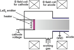
Figure 7. Schematic view of an arc discharge type plasma source with a heatable LaB6 cathode.
Download figure:
Standard image High-resolution imageThe shapes of the cathode and the anode and of the magnetic field lines connecting them define the mode of operation of the arc discharge. If the field lines directly guide the electrons starting from the cathode periphery towards the anode, as it is the case for the PSI-2 plasma source [76], the arc discharge 'burns' along the field lines. This geometry is favourable in terms of discharge ignition and stability. However, most of the discharge power is in this case released in the periphery region leading to a hollow radial plasma profile. Therefore, in many arc plasma sources, as those in PISCES [45] and in NAGDIS-II [50], the contact between the cathode and the anode along the magnetic field lines is inhibited. Instead, the arc discharge occurs across the B field. This principle is similar to the PIG (Penning ionisation gauge) type of gas discharge. The electrons emitted from the hot LaB6 cathode do not hit the anode directly and, instead, bounce several times along the plasma column reflected by the negative potentials of the target and the cathode. Therefore, this type of discharge is also referred to as 'reflex' arc [45]. The collisional transport across the B field drives electrons towards the anode, ensuring the discharge current. Since in this type of LPD, the discharge relies on cross-field transport, these types of devices tend to operate at lower magnetic field of ∼0.1 T or less. The geometrical projection of the cathode cross-section along the field lines to the anode position is a crucial parameter affecting the discharge properties. It can be controlled by the variation of the B field strength in the anode region, which allows a certain degree of control for generating a desired set of plasma parameters.
Some new LPD projects, aiming at increasing the plasma production rates to match the ion flux in the ITER divertor of ∼1024–1025 m−2 s−1, incorporate alternative types of plasma generators. The Magnum-PSI [24, 55–57] machine and its forerunner Pilot-PSI [54] employ a high-pressure cascaded arc source [77, 78]. This type of plasma source relies on an axial current to generate the plasma and therefore these sources operate best at higher magnetic fields of ∼1 T. For the MPEX project [79] at Oak Ridge National Laboratory, USA, an RF based helicon plasma source [80] is being developed, which is also compatible with a high magnetic field. An RF-based source may be an attractive alternative to an arc source because high plasma densities are generated with no internal electrodes, allowing steady state operation with reduced impurity generation.
One of the major drawbacks of PMI studies in LPDs are relatively low ion temperatures of typically a few eV at maximum. Applying a negative bias voltage to the sample can increase the incident ion energies at the target surface. This leads to an almost monoenergetic distribution of the incident ions. Moreover, the bias acceleration of ions towards the target results in a distribution of angles of incidence sharply peaked at normal angle. While this situation is ideal for studying incident ion energy variations to the surface (for example, measuring the sputtering yield versus ion energy), it eliminates the ability to investigate issues relating to the incident angle of the incoming ions. The PMI situation is different in a tokamak divertor, where higher ion temperatures lead to a broader distribution of both incident ion energies and angles. To increase the ion temperature in LPDs, attempts of applying additional heating, mostly RF based, systems were undertaken [81, 82]. However, the heating efficiency of these systems was rather low, possibly due to the relatively small plasma diameter and high neutral density.
3.1.3. Diagnostics for PMI studies.
Diagnostics in LPDs can generally be subdivided into three types; (i) systems ensuring a safe and reliable operation of the device ('machine diagnostics') and tools (ii) for the characterization of background plasma and (iii) investigating the interaction of plasma with the material sample. The latter includes the sample surface analysis.
A Langmuir probe is the most frequently used tool for the characterization of the background plasma, delivering the electron density and temperature and the plasma potential. The probe tip has to be inserted into plasma to measure the local properties, which requires caution to exclude the probe overheating. A linear drive to move the probe and measure the radial plasma profile is usually foreseen. The Thomson scattering of an intense laser beam provides a 'contactless' alternative to diagnose the electron density and temperature [83, 84]. However, the installation and operation of the laser requires significant efforts. Passive optical emission spectroscopy (OES) is, in comparison, technically less challenging. OES on helium is routinely used to monitor the electron density and temperature in tokamaks [85] and LPDs [86–88]. However, OES on hydrogen or deuterium [89, 90], which is the main plasma species in most PMI studies, is more challenging, requiring complex model assumptions and is therefore less precise in determining the electron density and temperature. OES is also used for measuring the composition of multi-species plasmas [91, 92].
The material surface can change its elemental composition, chemical state and morphology under plasma bombardment. The material can be eroded or, on the contrary, a layer of deposition can appear on the surface. To get the full picture of what happens to the material during the exposure, it is important to collect as much data as possible by various surface analysis techniques. Many of the techniques include a model to transfer the directly measured quantities into the sought-after parameters. Those models rely on correct and precise input parameters. Therefore, a cross-check of the determined quantities between various diagnostic methods is desirable.
During the exposure to plasma, the sample surface becomes chemically active and susceptible, e.g. to the exposure to air, which can significantly alter the surface state. Therefore, the immediate analysis of the samples during or after the experiments is desirable. According to where and when the sample analysis occurs, it can be separated in in situ, in-vacuo and ex-situ analysis. In situ techniques imply the analysis of material surface properties during the exposure, often delivering data real-time. The in-vacuo analysis is conducted after the sample exposure, but without exposing the sample to air. The ex situ techniques are applied after the transportation of the samples in air; they are often referred to as 'post-mortem' analysis.
OES on impurities eroded from the sample is the most widely used in situ surface analysis technique. The analysis of the line emission spectrum provides information on the surface composition and the erosion rate of the sample. However, the procedure of recalculation from the measured number of photons emitted by particular particles in a certain excited state to the total number of particles of this species in plasma is often challenging. Precise knowledge of the background plasma parameters and atomic physics data is required to keep the error margin acceptable. OES is also applied for in situ analysis of processes occurring in the main plasma in front of the target, e.g. recycling, detachment or acceleration towards the target.
A movable witness plate manipulator system is used in PISCES-B to collect redeposited material during the sample exposures [43]. The samples used to collect material can be either cooled of heated, so that any dependence of the hydrogen inventory in the redeposited mixed materials on the temperature of the plate during deposition can be determined.
A number of surface analysis techniques are usually used to characterize the sample after the plasma exposure. Electron beam based techniques include scanning electron microscopy (SEM), energy- and wavelength-dispersive x-ray spectroscopy (EDX and WDX, respectively) and Auger electron spectroscopy (AES). SEM, EDX and WDX are often combined in one single analysis device. SEM is used to visualize the surface structure with a resolution down to ∼10 nm, while EDX, WDX and AES are used to determine the chemical composition of the sample.
Ion beam analysis (IBA) techniques rely on a high energy (∼1 MeV) ion beam. IBA techniques include nuclear reaction analysis (NRA), Rutherford back-scattering (RBS), proton induced x-ray emission (PIXE) and enhanced proton scattering (EPS) and allow for a quantification of the material composition [93, 94]. The laser beam based techniques, such as laser induced desorption spectroscopy (LIDS), laser induced ablation spectroscopy (LIAS) and laser induced breakdown spectroscopy (LIBS) are a powerful tool to determine the amount of stored hydrogen in the samples (LIDS), their chemical composition in the presence of the background plasma (LIAS) or in the plasma locally created by the laser beam itself (LIBS) [83, 95].
X-ray photoelectron spectroscopy (XPS) and x-ray diffraction analysis (XRD) are two examples of x-ray based techniques. XPS provides the elementary composition as well as the chemical state, e.g. carbidization, of materials. XRD detects the crystalline structure of materials.
Other frequently applied techniques are thermal desorption spectrometry (TDS) for the analysis of the hydrogen retention in samples, secondary ion mass spectrometry (SIMS) for the depth resolved material composition, weight-loss measurements of the sample by high precision balances and surface profilometry by mechanical and optical tools.
One example of in situ analysis in the DIONISOS facility [58, 59] at MIT, USA is given in figure 8(a). Here, an ion beam accelerator is used for the ion beam analysis simultaneously during the plasma exposure, providing insight on the dynamics of PMI processes. A similar arrangement is used for the PS-DIBA facility in Japan [67]. Figure 8(b) shows the in-vacuo surface analysis station of PISCES-B [43]. The samples are extracted from the target station, after termination of the plasma discharge, by a swing-linear manipulator and inserted in the surface analysis station, where AES, XPS and SIMS techniques can be applied. For the PSI-2 device [51], the application of the laser based techniques including LID and LIBS is envisaged for in-vacuo surface characterization in the target exchange and analysis chamber (figures 8(c) and (d)). The sample carrier can be retracted after the exposure to plasma by a linear manipulator to the target exchange and analysis chamber, where it can be analysed by the laser based techniques. Mass spectrometry can be used for measurement of the desorbed deuterium, and a 2D optical spectroscopy system can be applied to detect the light intensity at a wavelength corresponding to a certain element on the surface. The plasma operation in PSI-2 can be continued with the retracted sample carrier using a removable plasma dump. The vacuum valves separate the exposure and the analysis regions of the vessel.
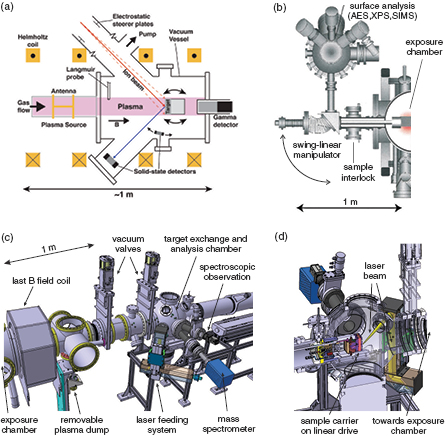
Figure 8. (a) In situ ion beam analysis in DIONISOS [58]; (b) in-vacuo analysis station of PISCES-B [43]; (c) PSI-2 target exchange and analysis chamber with a laser feeding system for in-vacuo analysis; (d) cross-section of the opposite side of the PSI-2 target exchange and analysis chamber including an illustration of a sample exposed to a laser beam [51]. (a) Reprinted from [58], with the permission of AIP Publishing. (b) © The Royal Swedish Academy of Sciences. Reproduced by permission of IOP Publishing. All rights reserved.
Download figure:
Standard image High-resolution imageDespite their advantages, in situ and in-vacuo analysis solutions have a significant downside of high complexity and costs. Therefore, most of the linear plasma experiments still rely on the ex situ surface analysis techniques. Another reason for the predominant use of ex situ is that the material samples can be transported to various laboratories specializing in particular analysis techniques, thus increasing the versatility and quality of analyses.
3.2. PMI research in linear plasma devices
3.2.1. Examples of PMI research in specialized linear plasma devices.
As has been stated in the introduction to section 3, the main advantages of LPDs with respect to conventional tokamaks for PMI studies are high particle fluence and well-controlled plasma exposure conditions, i.e. plasma composition, incident ion energy and sample temperature. Therefore, the research in LPDs is often aimed at effects distinctive for high fluence or specific exposure conditions. Topics of high importance for ITER, such as carbon chemical erosion [52, 96], erosion [97], fuel retention and blistering [98–101] of high-Z materials, influence of helium plasma irradiation of the surface morphology of tungsten [102–106] including W-fuzz formation [107, 108] and physics of detached plasmas [50, 89, 90, 109, 110] have been studied across different LPDs. In the recent years, the programmatic focus of the PMI research on LPDs has shifted towards qualification of tungsten as a first wall material. This research has contributed significantly to the decision of operating ITER with a full tungsten divertor from day one.
Of special importance are unique features of particular LPDs, resulting in their specific scientific missions. One example is the capability of the PISCES-B device to operate with beryllium [43]. Special safety requirements have to be fulfilled when operating with Be because of its toxicity. PISCES-B is installed in an air-tight enclosure with a secured access for personnel through a lock system. Beryllium can be introduced into the plasma by a high-temperature effusion cell. It has been found in the experiments with a graphite target and deuterium plasma that the yield of chemical erosion of carbon, Ych, decays exponentially after the start of Be seeding [111, 112] (figure 9). The characteristic time, τ, of the decay can be described as
where fBe is the concentration of Be in the plasma, Ea is the effective activation energy of the process and Ts is the surface temperature. The effect of chemical erosion mitigation has been attributed to the formation of a protective Be carbide layer and is potentially favourable for ITER, if carbon is used for the divertor.

Figure 9. Mitigation of chemical erosion of carbon by beryllium seeding in PISCES-B [111]. Reproduced courtesy of IAEA. Figure from [111]. Copyright 2006 IAEA.
Download figure:
Standard image High-resolution imageThe addition of Be to the plasma has also an influence on the D retention in graphite samples [113]. The beryllium seeding results in the formation of a protective beryllium carbide layer, which appears to prevent the in-bulk diffusion of deuterium, thus reducing the retention. In addition admixtures of He have proven to be especially effective at reducing the retention at the ITER relevant low ion impact energies Ei.
Beryllium under the bombardment by deuterium plasma in PISCES-B forms a fine-scale grass-like structure, which reduces the sputtering yield of Be [115, 116]. When a small fraction of argon is added to plasma, the surface morphology becomes smoother (figure 10), and the sputtering yields recover to the predicted values [114]. Aluminium targets exhibit similar phenomena, opening a possibility of performing beryllium relevant studies with aluminium targets on facilities not capable of handling beryllium.

Figure 10. SEM images of (a) a beryllium target exposed to pure deuterium plasma, (b) Be exposed to D plasma with 3% Ar, (c) and (d) Be exposed to D plasma with 10% Ar with two different magnifications, (e) Be exposed to pure Ar plasma and (f) Al exposed to pure D plasma studied in PISCES-B [114]. © The Royal Swedish Academy of Sciences. Reproduced by permission of IOP Publishing. All rights reserved.
Download figure:
Standard image High-resolution imageThe NAGDIS-II facility employs a high-pressure plasma generator [50] which allows the device to reach an electron density of up to 1020 m−3. At these high densities the physics of plasma detachment, crucial for the operation of the ITER divertor, can be studied.
The Magnum-PSI device [24, 55–57] can operate in a pulsed regime with a magnetic field of up to 1.73 T, producing an ion flux of up to 1025 m−2 s−1. Magnum-PSI is thus contributing to the PMI research at ITER-relevant high particle fluxes. Moreover, the pulsed operation mode of the plasma source in Magnum-PSI [73] allows simulation of ELM-like transient loads to the material samples.
As it was mentioned in section 3.1.3, the DIONISOS experiment is coupled with a high-voltage ion beam accelerator [58, 59]. Not only DIONISOS is used to investigate the dynamics of PMI processes using in situ ion beam analyses, it also provides an option to study the effects of the material irradiation by the beam particles. Such studies are important in view of material damage by the high-energy neutron irradiation in fusion reactors.
The TPE device [47–49] is installed inside a compact air-tight enclosure, glove box, and is, therefore, capable of operating with moderate amounts of tritium and low-activated material samples. In particular, TPE is an integral part of the Japan-US collaborative programme on the investigation on hydrogen isotope retention in neutron-irradiated and ion-damaged tungsten [47–49].
Mirror confinement type devices are also contributing to the reactor relevant PMI research by using their high particle and heat flux plasmas. In the GOL-3 multi-mirror trap at the Budker Institute in Novosibirsk, Russia, ITER relevant studies on the influence of simulated type-I ELMs on tungsten [117, 118] and carbon-based materials [119] have been carried out. The Gamma 10 tandem mirror device at the Tsukuba University in Japan has also recently initiated a project on PMI studies using one of the ends of the device as a source of a large-diameter, high-heat plasma flow (E-Divertor project) [120, 121]. Additionally, a novel divertor will be installed in the anchor region of Gamma 10 (A-Divertor) to combine the advantages of the axisymmetric mirror geometry with the tokamak-like divertor geometry.
Activities of PMI oriented LPDs are internationally coordinated by the 'Technology Coordination Programme on the Development and Research on Plasma Wall Interaction Facilities for Fusion Reactors' of the International Energy Agency 6 . Cross-machine investigations of fuel retention in tungsten for a large span of incident ion fluxes in Magnum-PSI and PSI-2 [101], erosion, surface modification and fuel retention in beryllium and aluminium under the influence of impurities in PISCES-B and PSI-2 [114] and response of W fuzz to transient loads between NAGDIS-II and Magnum-PSI [122] are examples of such international collaborations.
3.2.2. Modelling of PMI in linear plasma devices.
Numerical simulations are necessary for the interpretation and comparison of results from different devices, LPDs as well as tokamaks. In addition, the models allow for extrapolation of LPD results to conditions expected in future fusion reactors. The simulation models are validated by benchmarking against existing experiments and then applied to the predictive modelling for next-step devices. Several numerical codes which are routinely used for tokamaks, including the B2-EIRENE code [123] and the ERO code [124] has been adapted for the linear geometry.
The B2-EIRENE is a coupled kinetic neutral gas (the EIRENE part) and drift-fluid plasma (the B2 part) transport code [123]. The code has been adapted to the linear geometry by assuming a linear device as an zero aspect ratio, infinite pitch torus. Hereby, the toroidal coordinates transform into the linear geometry as toroidal to azimuthal, poloidal to axial and radial to radial, respectively. The code was applied to the PISCES-A and PSI-2 linear plasma devices and could reasonably reproduce the measured neutral gas pressure distribution and plasma parameters. One of the outputs of the B2-EIRENE modelling is the fractions of D+ , D2+ and D3+ ions in plasma, which has to be taken into account for the correct interpretation of PMI studies with deuterium plasma.
A zero-dimensional model solving the system of rate balance equations for ion and gas species was developed for calculations of the D+ , D2+ and D3+ plasma composition in the PISCES-A and PISCES-B devices [125]. The model was successfully benchmarked with measurements of the molecular and atomic ion concentrations by an omegatron-type mass spectrometer.
One of the most frequently used PMI modelling tools, the 3D Monte-Carlo code ERO, has been used for the simulation of experiments in PISCES-B and Pilot-PSI [126, 127] and PSI-2 [128]. The code simulated the interaction of plasma with the target including erosion, deposition and transport of impurities in the plasma.
Molecular dynamics simulations were applied to interpret the results of Be erosion in PISCES-B and showed that beryllium can be chemically sputtered via BeD molecules [129, 130]. The molecular dynamics simulations of BeD sputtering were linked to the plasma impurity transport code ERO in order to follow the behavior of sputtered BeD species in plasma. This multi-scale approach enabled direct comparisons with experimental observations of BeD sputtering in the PISCES-B facility.
A three-dimensional global drift fluid model was revisited for linear plasma devices [131] and applied for the NAGDIS-II device [132]. The numerical simulations reproduce several features of the intermittent spiraling structures observed, for instance, statistical properties, rotation frequency, and the frequency of plasma expulsion. A plasma source driven predator-prey like mechanism was identified as a potential cause of spiraling intermittencies in linear plasma devices.
3.2.3. Prospects of PMI research in linear plasma devices.
The next-generation LPDs are aimed to fill specific gaps in the PMI research towards ITER and future reactors. One of such scientific gaps are particle and heat fluxes in present LPDs being lower by about one order of magnitude than expected in ITER (see section 3.1.1). To increase these parameters, operation in a high magnetic field with a novel plasma source and additional plasma heating is necessary. The Magnum-PSI machine [24, 55–57] in its projected final stage will incorporate a high-pressure cascaded arc ion source and superconducting magnetic field coils, producing a steady-state field of 3 T. Additional RF based plasma heating is planned. The RF waves will be injected in the second differentially pumped vacuum chamber of Magnum-PSI between the plasma source and target. The RF power level currently considered is approximately 50 kW. Two RF heating methods are proposed: lower hybrid (LH) heating and ion cyclotron resonance (ICR) heating. The projected electron density of ∼1020 m−3 and temperature of 1–5 eV are relevant to the ITER divertor. The target will be inclined to simulate the divertor geometry. Magnum-PSI will be able to produce a particle flux of ∼1025 m−2 s−1 for perpendicular field line angle to the surface and ∼1024 m−2 s−1 for a ITER-relevant grazing field line angle to the target and a heat flux of higher than 10 MW m−2. A pulsed plasma source system to simulate ELM-like plasma transients was already realized by the superimposition of a DC plasma and a high-power plasma impulse, which is achieved by a capacitor bank system coupled in parallel with the DC power supply.
Another scientific gap on the road to the fusion reactor is testing of materials pre-exposed to high-energy neutrons, which can significantly deteriorate the thermo-mechanical properties of the materials. After the neutron irradiation, the materials are activated and subjected to corresponding safety restrictions. The devices for testing of such materials must be installed inside a glove box in the case of a moderate level of radioactivity, or inside a protective containment when operating with highly radioactive samples, e.g. in hot cells, which are shielded nuclear radiation containment chambers. Lead, or tungsten, are usually used as the shielding materials.
The JULE-PSI project [133] at Forschungszentrum Jülich, Germany, envisages a linear plasma device installed in the hot cell with an integrated in-vacuo analysis station (see also the detailed description in section 4.2.3). It will be capable of using toxic and highly activated materials to contribute in this reactor-relevant PMI field. The PSI-2 device [51–53] has been transferred to Jülich for the use as the pilot experiment outside the hot cell. Components and technological solutions will be tested at this 'cold' device before transferring them to the JULE-PSI device in the hot cell.
The concept of the new advanced plasma generator MPEX [79] at Oak Ridge National Laboratory, USA, foresees a new RF plasma source system including helicon wave plasma production [80] and electron and ion heating for an independent control of electron and ion temperatures to allow access to the entire divertor plasma parameter range. High densities at the target should be realized, requiring a high plasma production in the source. The material samples, including neutron-irradiated samples, will be placed in user defined target station containers, which will be coupled to the plasma exposure chamber. The anticipated plasma parameters in MPEX are similar to Magnum-PSI.
Besides new devices in the design or construction stage, the existing devices are frequently undergoing various upgrades to improve both the exposure parameters and diagnostic capabilities. The observable general trend is towards elaborate in situ, or in-vacuo, surface diagnostics to disclose the dynamics of plasma-material interaction.
In summary, linear plasma devices provide unique capabilities for reactor-relevant PMI research. The research in LPDs is both flexible and cost-effective and is complimentary to the studies in present tokamaks. The value of the research in LPDs increases if it is aimed at specific open issues for ITER and the fusion reactor. The main purpose of the new generation of LPDs is to close the scientific gaps on the road to a reactor, such as high particle and heat fluxes and the performance of neutron irradiated materials. Mirror machines and other existing plasma devices can contribute to reactor-relevant PMI research at moderate costs of hardware re-arrangement. The LPD specific technology-oriented research is needed for the further improvement of the quality of the PMI studies in LPDs. It includes the development of novel plasma sources, solutions for vacuum systems to operate with high gas amounts, flexible target manipulators and in situ/in-vacuo surface analysis methods.
4. Nuclear loads to components and materials
In fusion reactors, first wall materials have to withstand extreme loads with respect to heat flux densities, particle flux densities and fluences and also irradiation by high energy neutrons leading to damages up to 150 displacements per atom during the lifetime of a reactor. Synergistic effects from these different loads are governing the behaviour of plasma-facing materials. Dedicated PWI facilities such as linear plasma devices can be used to characterize and understand plasma-wall interactions and to qualify materials under conditions relevant to future fusion reactors. Such investigations are possible using material samples irradiated and pre-damaged by neutrons in a fission reactor or a future fusion neutron source and exposing these pre-damaged samples to relevant plasma conditions, including the simulation of transient heat loads as imposed e.g. by edge localized modes (ELMs) in toroidal confinement devices.
In this section, we summarize the impact of radiation damage due to neutrons on plasma-facing materials and components and give an overview of dedicated plasma test facilities, capable to test neutron activated materials and aiming at the investigation of the underlying PSI processes 7 .
4.1. Impact of neutron damage on plasma-surface interaction processes
In a fusion reactor, plasma-facing materials are exposed to plasma ions and electrons (including fast ion losses) and D-T fusion neutrons. While ions from the thermal scrape-off layer and the divertor plasma only penetrate into the wall material and produce defects on the scale of a few to 10 nm, neutrons penetrate on the scale of cm–dm and produce defects deep into both plasma facing and structural materials. Furthermore, the interaction of fast fusion neutrons with the lattice atoms will lead to transmutation effects. The energy deposition of neutrons close to the material surface is negligible with respect to that of plasma ions—therefore, the importance of neutrons for plasma-surface interaction processes could be questioned.
However, a strong impact of neutron damage onto plasma-surface interaction processes and the performance of plasma facing components can be expected because of two reasons:
- 1.The change of material properties caused by neutron irradiation (by defect production and transmutation) will severely degrade the power handling capabilities, in particular in view of transient heat loads caused by edge localized modes (ELMs) which will occur in very high cycle numbers for steady state operation different to what is observed in current confinement devices. In turn, the plasma-facing materials get prone to crack formation and melting (e.g. at crack boundaries). Erosion losses and dust formation will result—the synergistic effects of plasma and neutron loads will reduce the lifetime of plasma-facing components.
- 2.Fuel atoms (deuterium and tritium) will diffuse from the nm-thick implantation zone deep into the wall, in particular at enhanced wall temperatures and during long-time exposure as expected for a DEMO reactor. The fuel atoms will be trapped in defects originating from neutron irradiation. By this mechanism, the spatial scale affected by plasma-surface interactions is significantly extended into the bulk materials and the tritium inventory in the first wall dominated.
In this section, the main effects of neutron irradiation on plasma-facing materials and the current understanding of its impact on plasma-surface interaction via synergistic effects will be summarized.
4.1.1. Radiation damage and transmutation.
Fast neutrons with an energy of 14 MeV are produced in the D-T fusion process and irradiate the wall materials in a fusion reactor. The resulting characteristic energy spectrum of the neutron flux to first wall components substantially differs from the one in a fission reactor of similar thermal power as can be seen in figure 11 [134].
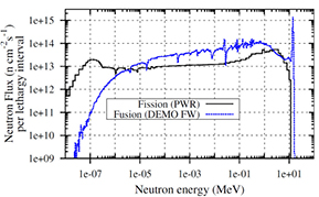
Figure 11. Energy spectrum of fusion neutrons in a DEMO type fusion reactor at the outer midplane of the first wall and of a fission reactor with comparable thermal energy of  [134]. Reproduced courtesy of IAEA. Figure from [134]. Copyright 2012 IAEA.
Download figure:
Standard image High-resolution imageAs a consequence, irradiation effects in plasma-facing materials are caused by both inelastic and elastic collisions of high energy ions and neutrons. For the fast fusion neutrons, nuclear cross sections become important and transmutation processes take place. The production of hydrogen and in particular also of helium and the subsequent formation of bubbles weaken the mechanical stability of the material and cause embrittlement. Reaction products with high recoil energy can significantly contribute to the production of displacement damage. Elastic collisions of irradiating particles lead to energy transfer to lattice atoms, producing so-called primary knock-on atoms (PKAs) which will be displaced, if the transferred energy is larger than the displacement threshold energy, and create a Frenkel pair (vacancy—interstitial atom pair). For high energy neutrons (or heavy ions), high energy PKAs give rise to displacement cascades.
However, the resulting displacements per atom (dpa) do not give information about the resulting changes of the microstructure, nor the change of material properties, as the time evolution of the material damage (recombination, migration and coalescence of defects and the temperature dependence of these processes) is not considered [136]. For tungsten as high heat flux material, transmutation to rhenium, tantalum and osmium is largest. The production of gaseous species as helium and hydrogen is much smaller and possibly negligible for high-Z materials, as can be deduced from figure 12 [135]. It can be expected that the change of chemical composition due to transmutation has significant effects on material properties, as will be discussed later.

Figure 12. Transmutation of W at the first wall of a DEMO fusion reactor [135]. Reproduced with permission from [135].
Download figure:
Standard image High-resolution imageIn a fusion reactor, metals and alloys are irradiated at temperatures where the primary defects (interstitials and vacancies) are mobile and will either recombine or escape from their birthplace [138]. Only the latter will give rise to a change of microstructure via clustering to dislocation loops, formation of vacancy clusters and—ultimately—large voids. Void formation in tungsten due to neutron irradiation up to 1.54 dpa in the fast fission reactor JOYO has been reported by Tanno et al [139]. The impact of rhenium has been studied by Hasegawa et al [137]. It has been found that Re atoms bind to self-interstitial atoms (SIAs) and thus the mobility of SIAs is decreased. As a consequence, void formation is suppressed in the presence of Re as can be seen in figure 13.
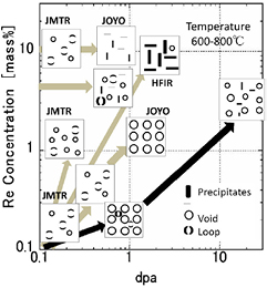
Figure 13. Evolution of the microstructure of W-Re alloys under neutron irradiation [137]. Reprinted from [137], Copyright 2014, with permission from Elsevier.
Download figure:
Standard image High-resolution image4.1.2. Physical and mechanical effects of radiation damage.
The physical and mechanical effects of radiation damage as summarized in table 4 depend on the both irradiation temperature (expressed here with respect to the melting temperature TM) and the displacement level [140, 141].
Table 4. Physical and mechanical effects of radiation damage [140].
| Process | Irradiation conditions |
|---|---|
| Radiation hardening and deformations | <0.4 TM, >0.1 dpa |
| Fracture and embrittlement | <0.4 TM, >
|
| Radiation-induced precipitation and segregation | 0.3–0.6 TM, >10 dpa |
| Irradiation creep and growth | <0.45 TM, >10 dpa |
| Volumetric swelling from void formation | 0.3–0.6 TM, >10 dpa |
| (High temperature) He embrittlement | >0.5 TM, >10 dpa |
At low irradiation temperatures the yield stress of metals and alloys is increased while the ultimate tensile stress is much less altered. As a consequence, the ductility of the material is significantly reduced due to irradiation as the defects hinder the gliding of atoms. The low temperature hardening leads to a ductile-to-brittle transition at a temperature (so called DBTT—ductile-to-brittle-transition temperature) below which the yield stress exceeds the cleavage stress (see discussion in [138]). Irradiation increases the yield stress but not the cleavage stress and thus increases the DBTT. Figure 14 shows the effect of irradiation on the hardening of W and the impact of rhenium [139]. It can be seen that the presence of rhenium favors irradiation hardening.

Figure 14. Irradiation hardening of tungsten and tungsten-rhenium alloys under neutron irradiation [139]. Reproduced with permission from [139].
Download figure:
Standard image High-resolution imageFigure 15 displays the increase of DBTT of tungsten under irradiation [142], thus decreasing the operational temperature window the upper limit of which is determined by recrystallization and creep. At high temperatures, transmutation to helium is the main cause for embrittlement. He is practically insoluble in metals and tends to precipitate into bubbles which might grow to void-like cavities e.g. at grain boundaries, which can initiate intergranular failures. At very high production rates for hydrogen isotopes also hydrogen embrittlement can be expected (at low irradiation temperatures), which is not important for tungsten. However, for the performance of plasma-facing materials hydrogen embrittlement has to be taken into account due to fuel implantation at the surface and diffusion into the bulk.
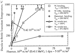
Figure 15. Increase of DBTT of tungsten with neutron irradiation fluence [142]. Reprinted from [142], Copyright 2000, with permission from Elsevier.
Download figure:
Standard image High-resolution imageThe influence of neutron irradiation on the thermo-physical properties is related to the irradiation temperature and the number of defects generated in the crystal structure. At temperatures below 1000 °C, the electrical and thermal conductivity of tungsten and tungsten alloys decrease with increasing irradiation dose. However, at elevated temperatures, as will occur in a fusion environment, the effect of neutron irradiation is mitigated by annealing. Complete recovery of defect-induced material degradation should occur at highest temperatures >1200 °C.
On the other hand, transmutation to rhenium will significantly decrease the thermal conductivity of tungsten as can be seen from figure 16 where the impact of rhenium concentration in W-Re alloys on the thermal diffusivity is depicted [143].
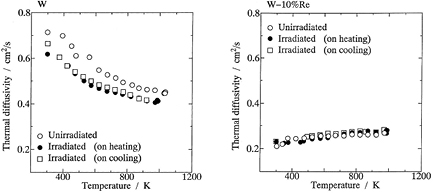
Figure 16. Temperature dependence of the thermal diffusivity of unirradiated and neutron-irradiated W and W-10%Re [143]. Reprinted from [143], Copyright 2000, with permission from Elsevier.
Download figure:
Standard image High-resolution imageIn summary, neutron irradiation and transmutation of tungsten as high heat flux material will severely limit the power handling capabilities of tungsten.
4.1.3. Impact of radiation damage on the lifetime of plasma-facing components.
Next, we will discuss the impact of neutron induced damage on the lifetime of plasma facing components. The contribution of neutrons to direct physical sputtering is negligible with sputtering yields Y < 10−4–10−6 (see [144]). This can be expected due to the very small energy deposition of neutrons close to the surface. Furthermore, very limited impact of damage on physical sputtering of ions is observed during plasma exposure of high energy ion irradiated tungsten to low temperature plasmas in the linear plasma device LENTA [145]. In these experiments, tungsten samples have been irradiated with 3 MeV helium ions up to damage levels of about 80 dpa before plasma exposure. The erosion yield has been determined by weight loss measurements to  independent of the pre-damage. In contrast, a significant increase of carbon erosion has been observed after ion irradiation [146].
While the yield of physical sputtering of tungsten by plasma ions is not enhanced by material damage from high energy ions, enhanced material erosion can be expected in a fusion reactor because of synergistic effects from heat and plasma loading onto neutron damaged plasma-facing materials. The additional material loss is linked to the damage of the surface of tungsten imposed by transient heat loads such as edge localized modes (ELMs).
Substantial progress in understanding of the damage thresholds in tungsten under repetitive transient heat loads has been made at Forschungszentrum Jülich. Tungsten samples in various specifications (grain orientation, purity, alloys and recrystallization status) have been exposed to transient heat loads in the electron beam facilities JUDITH 1 and JUDITH 2 and in the linear plasma device PSI-2, which is equipped with a laser facility to add ms laser pulses onto the plasma load to the samples.
Three loading parameters have been identified to govern the damage threshold for a given material: the base temperature of the sample, the energy density imposed to the sample and the pulse duration, combined in the heat flux factor F as a measure of the temperature increase and the pulse number. Altogether, these parameters describe a damage map of the material, where the thresholds for the onset of crack formation and for surface roughening define operational boundaries of the material.
An important finding is that at high pulse numbers damage such as crack formation is observed for base temperatures and heat flux factors where significantly less damage is observed at low pulse numbers [147] (see figure 17).
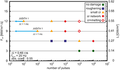
Figure 17. Damage threshold of tungsten after transient heat pulses with varying pulse number for a base temperature of 700 °C [147]. Reprinted from [147], Copyright 2012, with permission from Elsevier.
Download figure:
Standard image High-resolution imageRecently, it has been observed in experiments in PSI-2, that simultaneous loads by plasma impact and transient heat loads imposed by laser irradiation further decrease the damage threshold for a given pulse number. This behavior has been attributed to embrittlement of the tungsten material due to hydrogen implantation [72].
With the development of cracks at the tungsten surface, melting of crack edges, melt loss and erosion of loosely bound grains take place, giving rise to enhanced material erosion as can be deduced from figure 18. Enhanced erosion of loosely bound grains has also been observed under transient plasma and energy loads in the linear plasma device Pilot-PSI at the FOM—Differ institute [148].

Figure 18. Material damage and enhanced material erosion under transient heat loads at high pulse numbers [149]. © The Royal Swedish Academy of Sciences. Reproduced by permission of IOP Publishing. All rights reserved.
Download figure:
Standard image High-resolution image4.1.4. Fuel retention in neutron damaged materials.
The solubility of hydrogen isotopes in tungsten is negligible, therefore, tritium retention in a tungsten first wall material is completely determined by trapping in damage sites. The trap sites are natural trap sites from lattice imperfections, damage due to ion impact (plasma background and impurities) and trap sites from neutron irradiation. As a result, the amount of tritium retained is determined by the spatial distribution of trap sites, the binding energy of hydrogen in those sites and the temperature of the plasma-facing material which determines both diffusion from the material surface into the bulk and de-trapping from the trap sites.
Most of the investigations done so far are based on damage in tungsten imposed by high energy ion beams to simulate neutron damage. These investigations show that the irradiation damage increases the fuel uptake and is characterized by deep trap sites with activation energies for de-trapping ('trap energies') up to 2 eV [150–152].
During plasma impact, fuel atoms are implanted within the penetration depth of plasma ions, which is the order of 10 nm only. From there, the particles diffuse back to the surface, where the recombination rate will determine the surface concentration, and deeper into the bulk (see discussion in [153]). The atoms are trapped in trap sites. The filling of trap sites is governed by the binding energy, as well as the material temperature and spatial temperature distribution [154]. A careful determination of the trapping energies is a prerequisite to assess the retention process. This requires thermal desorption spectroscopy experiments after plasma loading of neutron damaged tungsten.
However, so far experimental capabilities to perform such experiments are very scarce. Only one plasma device is capable to expose neutron irradiated samples world-wide, the tritium plasma experiment TPE [47–49] at Idaho National Laboratory, USA (see section 3.1). Here, tungsten samples moderately irradiated by neutrons at the fast fission reactor HFIR up to damage levels of 0.025 dpa and 0.3 dpa were exposed [155–159]. Figure 19 [155] exemplifies the results obtained: at high sample temperatures, analysis of fuel retention done by nuclear reaction analysis (up to a depth of 5 μm) and by thermal desorption spectroscopy, where also hydrogen stored in the bulk of the material is released, differ significantly. These data show clearly that in neutron damaged tungsten trap sites well beyond the range of high energy ions are occupied at elevated temperatures.
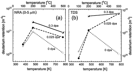
Figure 19. Deuterium concentration in neutron damaged tungsten after plasma exposure in TPE [155]. Reproduced courtesy of IAEA. Figure from [155]. Copyright 2015 IAEA.
Download figure:
Standard image High-resolution imageTo understand fuel retention in a DEMO scale fusion reactor, it is essential to study tungsten material at larger dpa levels. Such highly activated samples cannot be exposed in TPE without very long waiting times of several years and will be investigated in the new linear plasma device JULE-PSI [133], see table 3.
The impact of transmutation of tungsten to rhenium has been studied using high energy heavy ion irradiation of tungsten-rhenium alloys up to 0.9 dpa [160]. At temperatures above 700 K, a significant drop of the deuterium concentration has been observed with respect to tungsten bulk material, see figure 20. This difference can be attributed to the suppression of void formation due to the binding of Re to self-interstitial atoms (SIAs) which decreases the mobility of SIAs. It is important to investigate this effect further at high plasma fluences and for neutron irradiated tungsten (including transmutation products).
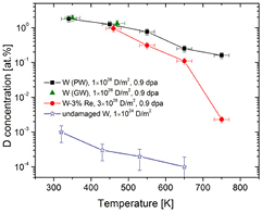
Figure 20. Deuterium concentration in heavy ion damaged tungsten and tungsten—rhenium alloys after plasma exposure [160]. Reproduced courtesy of IAEA. Figure from [160]. Copyright 2013 IAEA.
Download figure:
Standard image High-resolution image4.2. Experimental facilities for PSI studies with neutron damaged materials
Because of the substantial activation after neutron irradiation, in particular for tungsten, investigation of plasma-surface interactions with neutron damaged materials can only be studied in a controlled area using adequate shielding of the samples. Up to now, only one linear plasma device has been operational in such an environment, the Tritium Plasma Experiment at Idaho National Laboratory (INL), USA [47] (see section 3.1). Recently, a second device has been assembled, the Compact Divertor Plasma Simulator (CDPS) at Tohoku University, Japan [161]. The linear plasma device JULE-PSI [133, 162] is currently under construction at Forschungszentrum Jülich, Germany, and will be operated in a Hot Cell with highly activated material samples. The Material Plasma Exposure eXperiment (MPEX) is currently being designed at Oak Ridge National Laboratory, USA, and will be capable to produce plasma conditions as expected in the ITER-like divertor [79, 163]. These devices have complementary features and shall be introduced in this section. Operational parameters of the devices as electron density and temperature in the target region, ion temperature and particle flux density onto the target samples, magnetic field strength at the targets and plasma diameter are listed in table 5.
Table 5. Operational parameters of existing and planned linear plasma devices for exposure of neutron-irradiated material samples.
| TPE | CDPS | JULE-PSI | MPEX | |
|---|---|---|---|---|
ne

| 1016–
| 1018–1019 | 1017–1019 | up to 1021 |
Te

| 5–20 | 5–10 | 5–30 | 3–50 |
Ti

| 2–5 | 2–51–200 | ||


| 1020–
| 1021–1023 | 1021–1023 | >1023 |
B

| 0.1 | 0.02 | 0.2 | 1–2 |
d

| 50 | 20 | 60 | 120 |
4.2.1. Tritium plasma experiment (TPE).
TPE [47] is a linear plasma device based on a reflex-arc type plasma source (see also description in section 3.1). It combines three special capabilities for exposure of material samples to divertor relevant plasma conditions: (i) the use of tritium as plasma species, (ii) the exposure of beryllium and (iii) the exposure of radioactive samples. For that purpose, the device is located at the safety tritium applied research (STAR) at Idaho National Laboratory (INL). Here, the actual handling limits for tritium are given as  Bq (corresponding to a tritium concentration of up to 5% during a two hour exposure. The handling of radioactive materials is limited by the radiation dose (maximum 1 mSv in a year), the radiation dose rate (maximum 1 mSv h−1 at 30 cm), or the radioisotope inventory limit for tungsten isotopes corresponding
  Bq,
Bq,  Bq and
  Bq for 185W, 187W and 188W, respectively [47].
The device is located in a negatively pressurized room but not inside a hot cell. As a consequence, the typical cooling times required for tungsten samples with a weight of about 1 g are 800 days after irradiation to 0.3 dpa at the HFIR reactor at ORNL [155].
The operational conditions of TPE are summarized in table 5. Plasma diagnostics is mainly based on Langmuir probe measurements and ion current measurements at the target during biasing. The sample temperature is measured by a K-type thermocouple attached to the back of the targets. The heat is removed via thermal contact to a water-cooled copper plate. The target size can typically be varied from 6 to 51 mm [47]. Figure 21 illustrates the scheme of the TPE experiment.
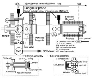
Download figure:
Standard image High-resolution imageThe device has recently been used for extensive studies of neutron irradiated tungsten samples to assess the impact of neutron damage on fuel retention as described before in section 4.1.4. In TPE, the neutron damaged samples are being loaded with deuterium and tritium, to assess the fuel content by TDS or NRA the samples have to be shipped to other laboratories.
4.2.2. Compact divertor plasma simulator (CDPS).
A new compact linear plasma device is currently being commissioned at the International Research Center for Nuclear Material Science, Tohoku University in Japan. The compact divertor plasma simulator (CDPS) [161] is based on a highly efficient DC plasma source developed at Nagoya University and uses a zizag shaped LaB6 cathode which is heated by direct Joule current (see also [164] for the basic features of this type of device). The plasma device is located in a radiation controlled area and is directly coupled to an already existing TDS device which allows determination of the retained hydrogen without air exposure after plasma irradiation. In the same laboratory, advanced analytical techniques such as TEM, SEM and 3D atomic probe measurements are available. In spite of the compact design of the device, high plasma densities can be achieved as depicted in table 5. Typically, it is foreseen to use miniaturized samples with a diameter of 3 mm and a thickness of 0.1–0.2 mm [161]. Figure 22 illustrates the scheme of the TPE experiment.
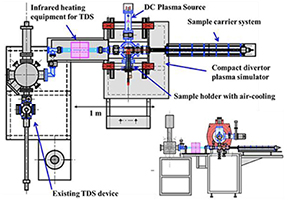
Figure 22. Set-up of CDPS with TDS system attached [161]. Reprinted from [161], with permission from JSPF.
Download figure:
Standard image High-resolution image4.2.3. Juelich linear experiment for plasma surface interactions (JULE-PSI).
The new linear plasma device JULE-PSI [133, 162] is currently under construction. It will be placed inside a Hot Cell in the High Temperature Materials Laboratory (HML) at Forschungszentrum Jülich to handle neutron irradiated materials. The handling limits in the laboratory are  for T (sealed, gaseous),
  for 181W and 185W and
  for 187W (arbitrary: dust and gaseous in solid enclosure), respectively. Tritium plasmas, however, are not foreseen.
JULE-PSI is based on a reflex-arc type plasma source and consists of a cylindrical vacuum chamber with several sections enclosed with magnetic field coils in a linear configuration. In the source region of JULE-PSI, a plasma column with a diameter of 60 mm is formed, then proceeding along the B field through the buffer region towards the target exposure region. The seven copper coils are water-cooled and capable of producing a steady-state B field of ∼0.2 T at the target exposure position. There are 6 turbo-pumps in the buffer and exposition region, two at the vacuum lock where the targets are brought in and one at the target exchange chamber, each with a nominal pumping speed of 800 l s−1. Vacuum pumps are mounted from the top to avoid contamination from activated dust particles [162]. Figure 23 illustrates the set-up.

Figure 23. Design of JULE-PSI [162].
Download figure:
Standard image High-resolution imageTransient heat loads can be simulated by means of a Nd:YAG laser with pulse energies up to 100 J and pulse lengths of 0.1–20 ms. The laser light is coupled via light fibers to the target analysis chamber and to the exposure chamber of JULE-PSI. The operation conditions of JULE-PSI are summarized in table 5.
Deuterium retention will be determined in-vacuo by laser induced desorption with quadrupole mass spectroscopy. The fuel content will be determined after the plasma exposure, when the sample is moved to the target analysis chamber of JULE-PSI without exposing it to air. This technique has been successfully applied at the linear plasma device PSI-2 (see section 3).
4.2.4. Material plasma exposure experiment (MPEX).
At Oak Ridge National Laboratory (ORNL), a pre-conceptual design for the new linear plasma device MPEX has been developed [79, 163]. MPEX is based on a helicon plasma source and will be equipped with ion cyclotron and electron Bernstein wave heating systems to produce plasma conditions relevant for the ITER divertor with power flux densities up to 20 MW m−2 and plasma flux densities up to 1024 m−2 s−1. The device is planned to be equipped with super-conducting magnets and water cooling of all parts in contact with plasma to allow for steady-state operation. It is planned to provide handling capability of neutron irradiated samples [165] (e.g. irradiated in the fission reactor HFIR at ORNL) by means of a removable target exchange chamber, from which the target can be moved to the plasma material interaction chamber with the help of a telescoping slide. The target (typically cone-shaped with a base diameter of 12 mm, top diameter of 10 mm and a thickness of 1 mm) will be assembled in a target puck [163]. The target exchange chamber is coupled to the PMI chamber with the help of an automated vacuum coupling system and can be maintained under vacuum down to 10−7 mbar by a separate pumping system after removal from the PMI chamber for further analysis of the material samples. A pre-conceptual model of MPEX is depicted in figure 24.

Figure 24. Pre-conceptual model of MPEX [163]. Reprinted from [163], Copyright 2016, with permission from Elsevier.
Download figure:
Standard image High-resolution image
5. Materials and component exposure to fusion plasmas in toroidal confinement devices
5.1. Material tests in tokamaks
Plasma-wall interaction (PWI) processes determine the material choice in ITER and DEMO. Here Plasma scenarios need to be compatible with material constraints. Hence, a review on plasma-facing components (PFCs) and material tests in toroidal confinement devices as the precursor experiments will be attempted here. In contrast to section 3, where many of the issues have already been discussed, different aspects of the PWI studies are described in an effort to demonstrate the efforts undertaken in current day fusion reactor precursor devices. This work drove understanding of the underlying physics with the aim to extrapolate to a fusion reactor. Typical material options considered include carbon (graphite, CFC), tungsten, and beryllium. In the following the focus lies on these options. PWI processes such as steady state or transient erosion and tritium retention have been studied for both low-Z (Be, C, 'CFC') and high-Z materials (W, Mo, 'steel'). Related to this, dust generation is still a process which requires more attention—for instance conversion from gross or net erosion to dust. For low-Z materials the build-up of the tritium inventory is dominated by co-deposition [166] as recently been highlighted again also for beryllium layers in JET and ITER. For later ITER phases and the extrapolation to DEMO additional tritium trapping sites due to neutron-irradiation damage need to be taken into account. Preferential sputtering and surface morphology evolution are crucial when trying to determine lifetime and plasma performance of PFCs. In addition to the particle loads heat loads are a crucial part of applying PFCs in current day fusion reactor precursor devices. Here also test of PFCs under high heat fluxes, up to melting, need to be considered together with their impact on the plasma 8 .
As the negative aspects of applying carbon as a first wall material for fusion became apparent, the qualification of metals—and in particular also high-Z materials—was reinvigorated. Beryllium and tungsten are currently considered as the materials of choice for the next step device ITER [4, 41], while tungsten seems to be main plasma-facing material option for PFCs in DEMO. This came about despite the early experience that high-Z materials show unfavourable impact on plasma performance, as described for PLT [167, 168] and JT-60 [169], as well as in earlier experiments. Tungsten and high-Z materials do pose problems in relation to plasma performance due to their strong radiative losses. A brief discussion of tungsten as fusion PFC is found in [170–172]. Tungsten suppresses sputtering due to its high atomic mass compared to the sputtering ions. It also allows for a good power exhaust, as tungsten has a rather high thermal conductivity, combined with a high melting point, and can hence facilitate higher heat exhaust than e.g. steel. Tungsten has, however, several issues related material properties [173] and plasma performance due to its relatively high Z.
Together with C-Mod [174–176], built as a full molybdenum high field tokamak, ASDEX Upgrade started a re-introduction of tungsten. ASDEX Upgrade first exchanged the divertor and then the first wall material during 1996–2007 [177–180]. In parallel to the introduction of tungsten in machines like ASDEX Upgrade, dedicated studies were performed to understand the basic physics mechanisms of exposing a fusion plasma to high-Z first wall materials.
In order to study the impact of the material mix for ITER [4, 41] on plasma operation, the JET ITER-like Wall (JET ILW) was implemented. This allows to test the beryllium first wall together with the tungsten divertor [181]. The feedback on the actual fusion plasma was the main driver for testing materials and components in current day toroidal experiments. This cannot be tackled on a laboratory scale. The synergistic effects of the complex loading conditions in a tokamak, as compared to loading conditions in laboratory devices and test stands, are unique.
The first wall of large scale fusion reactors or current precursor experiments cannot be exchanged on short time scales. Furthermore, controlled experiments are required to understand basic PWI mechanisms. As a consequence, several machines have introduced dedicated material test stations, or dedicated programs to exchanges wall samples or full wall tiles on a regular basis. In the following, a brief overview on existing systems is presented. In ASDEX Upgrade the divertor manipulator [182, 183] was used for both low-Z and high-Z experiments. In the case for introducing tungsten several experiments were performed to determine the transport of tungsten from the divertor to the main chamber [183–187].
Recently, ASDEX Upgrade changed its divertor by introducing a full bulk tungsten divertor. As part of this effort a new large divertor manipulator was integrated to allow the exchange of two full-sized divertor tiles [188–191].
TEXTOR, as a limiter tokamak operated until 2013, had two lock systems to expose limiter and material samples to the edge plasma [192]. Both systems were well diagnosed by means of spectroscopy and equipped with gas inlets for the study of material transport and deposition processes [193–196]. More details below.
In the US, both DIII-D and NSTX, NSTX-U have the possibility to introduce materials into the divertor. For DIII-D the so-called DiMES manipulator [197] is introduced into the flat floor of the divertor [198–200] allowing exposure, observation and exchange of material samples. For NSTX and NSTX-U a materials test station (MAPP) can be used to also analyze samples in-vacuo after exposure by means of e.g. XPS [201–204].
For the EAST tokamak a mid-plane manipulator system is routinely used to expose materials to the plasma [205].
ITER has also identified the need to monitor the wall evolution by materials samples. As components cannot be easily exchanged an effort was undertaken to establish an exchangeable samples program, e.g. bolts and small samples. This program allows ex situ analysis of tiles without the need to exchange whole components [206].
The effort at ITER is similar but not as comprehensive as e.g. the efforts described in [207]. At JET, with the newly installed ITER-like Wall, an effort was made to replace and exchange a whole poloidal cross sections of tiles to document the wall evolution under the Be/W wall. Dedicated erosion and deposition measurements were performed [208] together with studies related to fuel retention [209].
One crucial aspect of all these efforts are in situ diagnostics, to measure erosion fluxes [210–212], but also material inventory like hydrogen retention or material composition of redeposited layers [95, 213–222].
5.2. Fusion material issues investigated in toroidal confinement devices
5.2.1. Erosion—migration—deposition.
When discussing lifetime of the first wall of a fusion reactor the issues of material migration, hence erosion and re-deposition, are crucial when considering the function of the material as an armour of the structural components. For a long time carbon was discussed as first wall material. Carbon does not melt, and has an almost negligible impact on plasma performance apart from issues related to dilution. Issues related to irradiation of carbon PFCs [223] in conjunction with the issue of fuel retention [166] have, however, lead to the exclusion of carbon in ITER and most likely future fusion power devices [4, 41]. Many of theses conclusions have been reached based on dedicated tokamak exposures [166].
Carbon as first wall material.
A large number of experiments have been performed to study particular effects related to carbon as a first wall material. The erosion of carbon below its threshold for physical sputtering has triggered a large number of experiments. Here the analysis of the so-called chemical sputtering of carbon was the main focus. As the fusion plasma consists mainly of hydrogen ions, the formation of hydrocarbon molecules is one of the main mechanisms to erode carbon despite low energy impact physical sputtering being suppressed. Here dedicated injection, erosion, and deposition experiments have been performed in DIII-D/DiMES [224–230], TEXTOR [193, 231–233] and ASDEX Upgrade [234]. In addition global studies on migration were performed, e.g. described in [235]. Both carbon and boron are deposited more efficiently and/or show less erosion on graphite than on tungsten, particularly in the outer divertor. For 13C, the difference is 10–100 in favor of graphite. This is most probably caused by a higher re-erosion from tungsten surfaces.
These studies have always been complemented by modeling [229, 236–240]. The modeling shows good agreement with the observations if reflection coefficients based on molecular dynamics simulations are used. In contrast to plasma-wetted areas, no enhanced erosion has to be applied [193, 241]. For divertor plasmas ERO simulations of hydrocarbon transport together with SOLPS 5.0 [242] showed an increased carbon deposition efficiency in reversed field, particularly upstream from the source, than obtained in the normal ASDEX Upgrade field configuration. The deposition patterns point towards a significant poloidal hydrocarbon  drift in the divertor regions [243]. Critically identified was also the surface structure of carbon on its erosion properties [244]. In addition to graphite and CFC, also the use of diamond as a PFC was evaluated [245].
One issue that is crucial of any erosion process in a future fusion reactor has only been identified recently—the influence of externally applied resonant magnetic perturbation (RMP) fields. RMP fields are a candidate method to suppress high transient heat loads in tokamaks caused by edge localized modes (ELMs) [246]. Measurements at TEXTOR, on well diagnosed test limiters, provide evidence of a particle migration dominated by an  drift within stochastic zones of the 3D plasma boundary [194].
Work on diagnosing chemical erosion processes and extrapolating the carbon transport was performed at all carbon machines. It was concluded that in particular the deposition of a:C-H layers and their inherent co-deposition of hydrogen was an issue for operation of ITER as their are limits on the tritium inventory [166].
One sideline was at one point the use of B4C coatings for the Wendelstein W7-X stellarator, as they were considered as protective layers for the plasma-facing first wall panels. Here also testing by means of test limiters was performed. [247]
Tungsten as first wall material.
Tungsten is one of the best material choices to suppress erosion, due to its high threshold for physical sputtering [248–250]. As tungsten is, however, strongly detrimental to the performance of a fusion plasma [251–253] the study of tungsten erosion processes was also performed by means of studies in manipulator facilities.
In ASDEX Upgrade the divertor manipulator was used for both low-Z and high-Z experiments. In the case for introducing tungsten several experiments were performed to determine the transport of tungsten from the divertor to the main chamber. [183–186]. The use of W(CO)6 [185, 186] allowed to determine the influx of tungsten by a well-defined source, similar to experiments performed at TEXTOR utilizing WF6 [193–195]. In both cases the erosion, deposition, as well as the redistribution around the torus were studied. It was observed that W released in the divertor is well retained. Main chamber sources are much more dominant [187].
The erosion of tungsten has been studied in quite some detail. Only a few publications of recent work can be given here, in particular tackling the comparison of JET and ASDEX Upgrade [187, 212, 254, 255]. As mentioned above the focus was put on the transport and the gross versus net erosion of tungsten based on experiments with the ASDEX Upgrade manipulator [182, 184], and TEXTOR [194] including modeling [239]. For the recent overview of the tungsten tokamak ASDEX Upgrade refer to [256], with an overview on injection and erosion studies at the TEXTOR limiter lock given in [193, 257].
Similar experiments on tungsten erosion and deposition, together with modeling validation, have recently been performed in DIII-D [258, 259]. This includes the exposure of nano-structured tungsten [260] (see below) and the comparison of vacuum plasma sprayed (VPS) tungsten exposed to PISCES and DIII-D plasmas [261]. Studies regarding net versus gross erosion of high-Z materials in the DIII-D divertor (DiMES) were performed. [262]. These include molybdenum erosion [263, 264], and the mitigation of high-Z erosion by means of seeding gases [265].
One of the areas of interest is the dependence of the erosion of tungsten under very high heat flux, and hence elevated temperatures close to melting [266, 267]. It was found that when properly accounting for effects of elevated temperatures no temperature-enhanced erosion can be found within the uncertainties of the experiments. Tungsten at elevated temperatures behaves purely as expected [248–250].
As mentioned above not only the divertor manipulator, but also the use of dedicated samples is meant to facilitated understanding. The effect of surface roughness on the long-term erosion patterns of tungsten coatings was investigated in the outer strike-point region of ASDEX Upgrade during the 2010/11 campaign. A total of ∼6000 s of plasma operation was analyzed [268]. When the surface roughness was  μm, the net erosion rate was 0.03 nm s−1. This value was reduced by a factor of 2–4, as the roughness increased to
  –6 μm. Similar experiments were performed for new tungsten grades [269] using the TEXTOR limiter lock system.
Comparison between the erosion and re-deposition of tungsten and carbon was performed using so-called twin limiters [195]. In conjunction with existing experiments [185, 186, 193–195] a method was applied to qualitatively analyze tungsten spectra from the edge plasma.
As the interaction surface of tungsten test limiters was limited various experiments have been performed by replacing the main limiters at TEXTOR with VPS tungsten on graphite limiters [270]. In contrast to expectation no significant limitation on operation was found. Local emission and core concentration of tungsten in TEXTOR-94 were measured [271].
Plasma-facing components in ITER will be castellated by splitting them into small-sized blocks to maintain their thermo-mechanical stability. However, there are concerns in particular on retention of co-deposited radioactive fuel in the gaps (see below). Deposits containing up to 70 at.% of tungsten in the gap areas closest to the plasma were detected in recent experiments [272]. Deposition in the gaps accompanied by metal mixing demand for development of effective cleaning techniques. In experiments with ITER-like castellation, the gaps were cleaned from carbonaceous deposits using oxygen plasmas at 350 °C. Studies on gaps were performed in the divertor manipulator at ASDEX Upgrade and at the limiter-lock facility at TEXTOR. They are usually accompanied by modeling efforts [273, 274]. Originally studies included also macro-brush studies based on CFC [275].
Next to tungsten also the use of EUROFER steel is discussed as PFC for a DEMO reactor [276]. Experiments in the divertor manipulator and other systems can be clearly beneficial. P92 components are already being tested in ASDEX Upgrade and analyzed by means of spectroscopy and post mortem methods, in comparison to tungsten [277]. Steel is eroded 3–10 times faster than W, but could be used at the top and inner parts of the main chamber where the erosion rate is ∼0.01 nm s−1.
Similar material test studies were performed in a molybdenum environment. In the Alcator C-Mod divertor a toroidally continuous row of bulk tungsten tiles was installed near the typical location of the outer strike point and was removed for analysis after two campaigns [278].
Knowledge of the underlying plasma transport mechanisms and the surface processes based on lab and tokamak exposures allowed in turn to develop modeling, predicting the wall evolution of current and future devices [279–281]. Theses modeling studies are usually fed and supplemented by experiments performed using traces elements for easy detection of migration (e.g. 15N, 13C) [282–287]. Here either injection from the divertor manipulator or limiter lock is used or global gas injection systems are applied. Experiments also included the use of molybdenum as a trace element to distinguish from the tungsten background. Both WF6 and MoF6 were injected from a local limiter in the TEXTOR lock system [288, 289].
In EAST the mid-plane manipulator (MAPES) was used for material migration studies with an ITER first wall panel proxy [290]. The focus was here on material lifetime estimates for the beryllium first wall in ITER. Work along the lines of using a beryllium proxy element, e.g. aluminium, was also performed using DiMES [291].
A few unique issues related to erosion and deposition deserve special attention. These issues relate to the testing and qualification of diagnostic mirrors, but also production of dust.
Diagnostics mirrors.
Related to erosion and deposition is the lifetime of optical components in a fusion reactor. Optical and laser-based diagnostics in ITER will use mirrors to transmit plasma radiation and laser light to the corresponding detectors and cameras.
Mirror surfaces will be sputtered by plasma ions and neutrals and contaminated by impurities. These effects lead to the degradation of the reflectivity and hence change the performance of the corresponding diagnostics. By means of the manipulator systems or dedicated mirror stations expositions studies on the selection of candidate material have been performed The tokamaks EAST [292], DIII-D [293, 294] and TEXTOR [295–297] among others [298–302] have participated in these studies. Various methods including thermo-oxidative wall conditioning [303] or seeding of gas as a protective method have been evaluated [304]. It was shown by experiment and modeling that passive methods like shaped ducts and introduction of fins can mitigate the particle flux and hence the damage behavior [305–307]. Dedicated mirror test stations have been installed in several tokamaks while a coordinated effort was undertaken to select materials [292, 301, 308, 309]. The conclusion is that apart from requiring cleaning techniques single crystal mirrors seem to behave best, due to their homogenous material structure and erosion behavior [295]. One of the crucial systems where mirrors are used is e.g. the CXRS diagnostics system for ITER [310]. For more details refer to the publications on the above mentioned studies [293–302, 304, 306–313].
Dust.
Due to divertor and wall erosion an area of fusion research is the study of dust produced during operation. Dust will have severe impact on the performance of ITER. The accumulation of tritium in dust represents a safety issue 9 . A possible reaction of dust with air and steam imposes an explosion hazard and the penetration of dust into the core plasma may degrade plasma performance by increasing radiative losses. In addition, hot beryllium dust is considered a safety limit for ITER operation. Even though it is yet unclear how much of the material that is eroded eventually converts into dust, studies have focused recently on the dynamics of dust particulates observed in tokamaks and stellarators with a size range between 10 nm and 100 μm [314, 315]. Studies have been performed in several tokamaks covering both limiter configurations such as TEXTOR [192, 316] and divertor machines like DIII-D [198, 317]. Moreover, studies how to detect and study dust in ITER were undertaken [206]. In order to allow for controlled particle sizes and easy implementation of experiments, dust studies have been performed utilizing either limiter lock systems [192] or the DiMES manipulator [198].
It has been known for a long time that microscopic dust appears in plasmas of fusion reactor. Recently it was shown that dust can be responsible for the termination of long discharges. A single droplet of 30 μm size if completely disintegrated and radiating in the core will give rise to additional 100 kW to few MW [318–320], as is clear from the radiation in the core [252, 321, 322]. Larger droplets can cause the radiative collapse of the plasma discharge. Also, in ITER-scale experiments dust can pose safety problems related to its chemical activity, tritium retention and radioactive inventory. The presence of dust in the vacuum chamber of ITER was one of the main concerns during the ITER licensing process. Crucial are the dust dynamics and transport in fusion plasmas [323, 324].
In addition to the production of dust from deposition of layers and their spallation during operation, fine spray of tungsten droplets [318] (so-called layer spraying) is observed when exposing tungsten to melt conditions, as observed in several devices. This can lead to a large increase of the W release (100 times larger than the W sputter source before melting), which increases the core W concentration significantly [325]. If droplets are released from the PFC their impact on the plasma does depend on their evaporation and lifetime [326, 327].
The efficiency of dust generation during transient heat and particle loads remains an issue. Disruptions and ELMs release notable amounts of dust in DIII-D [314, 328]. Arc erosion is also one of the mechanisms given [329]. Experiments with artificially introduced dust in DIII-D and TEXTOR showed that depending on the location of release dust can migrate from the divertor into the main chamber in DIII-D, but does not penetrate the core plasma at TEXTOR. Generally, dust studies reveal a quite benign effect on plasma performance in TEXTOR [311].
Mobility and release of dust has been tackled based on the experiments also by applying theoretical understanding—in contrast to previous work [323, 324] incorporating standard dust-plasma interaction processes, new work also encompasses major mechanical aspects of dust–surface collisions [330–332].
5.2.2. Surface morphology evolution.
Of particular interest is the evolution of surface morphology of tungsten under fusion plasma conditions. Much work was done on PFCs from various tokamaks without the use of manipulators. The benefit of using controlled exposure experiments, however, is the dedicated post mortem analysis to be performed. One aspect of special interest is the formation of blisters on the tungsten surface. Pre-characterized polycrystalline tungsten samples were exposed close to the strike point using the divertor manipulator system in the outer divertor plasma of ASDEX Upgrade [333]. It was found that exposure to plasmas (510 discharges) containing wall material species and varying impurities (He, N, W, C, B, O) leads to formation of blisters comparable to those found in laboratory experiments on polished W surfaces under similar exposure conditions [182, 334]. This is one indication that controlled lab experiments together with tokamak exposures can facilitate clear extrapolation to future devices.
An issue raised from observations in linear plasma devices (see section 3) is the production of so-called tungsten fuzz. W fuzz are surface nano-structures growing on tungsten exposed at elevated temperature to helium plasmas. Tungsten fuzz has been studied in various configurations [104, 107, 335]. A series of measurements coupling plasma exposures in PISCES and DIII-D [260, 336] have been exposed W samples with various surface morphologies. During theses experiments a mitigated erosion behavior has been found, as well as no additional roughening of the surfaces during ELMs. Fuzz under theses condition actually improves the PWI behavior. Similar work has been performed at TEXTOR [337]. Here the conclusion was that W fuzz after exposure to the TEXTOR edge plasma was either completely eroded or covered by a carbon deposit. The main impurity in TEXTOR is carbon. On the W fuzz surface, C deposition was enhanced compared with a flat W surface, probably due to reduction of the effective sputtering yield and the effective reflection coefficient of carbon ions, similar to roughness effects. No clear indication of W fuzz growth under the TEXTOR or the DIII-D conditions was found. Only recently fuzz growth was observed under tokamak conditions [338]. Here a material sample—namely a prepared screw head instead of a manipulator—was used. For more work outside of the tokamak environment refer to [104, 335, 339, 340] and sources therein.
5.2.3. Deposition and retention.
For several reasons fuel retention is crucial when discussing plasma-material interactions in a tokamak. First and foremost it is related to the operational viability of a fusion power plant. In the course of the development of fusion power the quantitative breeding of tritium was identified as one of the crucial aspects. For each tritium atom used in the fusion reaction, a new tritium atom needs to be produced. Additional tritium production is required to cover losses and tritium for fueling further power plants. For a DEMO reactor or a future power plant the tritium breeding ratio needs to be of the order of 1.1–1.2 to cover modeling uncertainties and losses, as well as to allow for the start-up of additional power plants [341]. For tritium breeding the material choice can be crucial [315, 342].
Experiments with tritium can and could only be performed in the TFTR and the JET tokamaks [343–345] within a fusion relevant environment. Hence, typically work in test systems and in tokamaks was and still is performed based on hydrogen or deuterium plasmas. Crucial is here also to understand the interaction of molecular, atomic and total particle fluxes of deuterium in front of the PFCs. In TEXTOR limiter experiments were performed, the temperature of which was controlled independently of the plasma conditions [346].
For retention studies using material test stations a large range of work was spawned [347–350], also linked to other devices such as NSTX [204, 351, 352], ASDEX Upgrade [353] and DIII-D [198, 199, 354]. Based on lab experiments and linear devices, as described above (section 3.2.1), blisters and fuel retention related structures were studied by means of e.g. the divertor manipulator in ASDEX Upgrade [182, 333, 334]. Retention-related PWI studies were also performed in the MAPES facility at EAST, with a focus on retention of fuel by means of co-deposition in gaps [205].
When trying to extrapolate to future devices also the in situ assessment of deposition and fuel retention in materials is of crucial importance [95, 214, 217]. Utilizing lasers as means of in situ release mechanism for fuel species was intensely studied especially at TEXTOR [218, 219, 222] with a focus on a:C-D layers—co-deposits with carbon [215, 216, 220, 221]. This work includes studies on tungsten materials even though main mechanisms here include implantation and hence require melting of the surfaces to release the fuel [355]. Efficient removal techniques need also to be developed and tested [196, 213]. Here methods of e.g. ICWC [356] were tested on limiters pre-deposited with various layers and mixed materials [357].
Deposition is of particular interest for castellated structures in future devices. The deposition in gaps is in this case directly linked with fuel retention. This is a major issue especially for carbon re-deposition. Plasma-facing components for ITER will be manufactured as macro brush structures or with castellated surfaces. Material samples with gaps of similar geometry as intended for ITER were exposed to different plasma conditions in TEXTOR, DIII-D and ASDEX Upgrade. In all devices a decrease of both carbon and deuterium inventories at the side faces from the gap entrance into the gap with scale lengths in the mm range was found [224, 272–274, 354, 358, 359].
To study the influence of plasma exposition on tritium retention post-plasma exposure experiments with tritium loading were performed, as e.g. described in [360, 361]. In this study, the retention of tritium in tungsten pre-exposed in the limiter region of TEXTOR to deuterium plasmas of low energy in the presence of small carbon impurity levels was examined. The tungsten samples were subsequently exposed to a gaseous tritium/deuterium mixture. This allows to study the outgassing and isotope exchange of fusion-plasma exposed materials with hydrogen isotopes. Similar experiments were performed on various fine grain tungsten materials exposed and molten in TEXTOR, as described in [362].
A fascinating aspect of hydrogen retention is studied by utilizing tungsten and tantalum limiters at the TEXTOR tokamak. An effort was made to distinguish between fuel recycling on endothermic (W) and exothermic (Ta) hydrogen absorbers [363]. As a consequence of thermodynamic properties with respect to hydrogen, significantly greater fuel retention has been detected in tantalum than in tungsten.
Work for ITER is based mainly on in situ laser diagnostics [95, 214], but also removable samples [206].
Recently, the impact of seeding gases (N2, Ne, Ar) on fuel retention (and also the retention of seeding gases themselves, here mainly nitrogen) was studied directly in ASDEX Upgrade [364]. Using the divertor manipulator system, tungsten samples were exposed to well-characterized L-mode plasmas with and without nitrogen seeding. These experiments were especially used to benchmark modeling of the first wall evolution [279–281]. Similar experiments have been performed at TEXTOR [282] with a 15N tracer to study nitrogen migration and retention. Here both limiter surfaces as well as test limiters have been used to quantify the migration and deposition [287].
Power handling and melting.
As power handling and melting are discussed elsewhere 10 here only briefly the use of divertor manipulator and test stations to evaluate the issue of power handling of components is mentioned. In particular exposures of small tungsten samples, or pins, were performed to study melt layer dynamics [318, 365–370] and particle release into the divertor [327, 371]. Utilizing high-resolution camera images the droplet motion could be observed [372] and compared with 3D plasma modeling. These experiments have benchmarked with melt layer modeling and have clarified that the release of tungsten droplets in the divertor poses less of a risk than anticipated to the plasma due to good divertor retention. The benefit of all the possible material test stations in tokamaks is that also high-risk experiments and out-of the box concepts can be tested, e.g. melt experiments, rotating limiters [373] or liquid metals [374, 375].
Alltogether, it is apparent that utilizing manipulator systems as well as dedicated test sample programs have driven the PWI and materials development for application in fusion reactor supported and sometimes driven by work on linear plasma devices (section 3). New materials have been introduced based on issues raised during the experiments in close link with lab experience. Materials qualification and development certainly doesn't stop here, several issues like erosion and especially transient heat fluxes are as of yet unresolved and hence advanced materials solutions are to be developed [173] that in particular are tailored to the neutron environment of a future fusion reactor. Here dedicated experiments on toroidal devices are crucial to make the final step for application, while studies related to basic properties are best performed in the controlled environment of linear plasma devices (section 3).
Acknowledgement
Part of the work described here has been carried out within the framework of the EUROfusion Consortium and has received funding from the Euratom research and training program 2014-2018 under grant agreement No 633053. The views and opinions expressed herein do not necessarily reflect those of the European Commission.
Footnotes
- 5
See also: Ueda et al Status of the Development of Baseline High Heat Flux and Plasma Facing Materials for Fusion, this special issue.
- 6
- 7
For a description of neutron radiation effects in tungsten, see: Ueda et al, Status of the Development of Baseline High Heat Flux and Plasma Facing Materials for Fusion, this special issue.
- 8
See: Ueda et al, Status of the Development of Baseline High Heat Flux and Plasma Facing Materials for Fusion, this special issue.
- 9
See also: Taylor and Merrill, this special issue.
- 10
See: Ueda et al, Status of the Development of Baseline High Heat Flux and Plasma Facing Materials for Fusion, this special issue.