


Abstract
IFMIF, the International Fusion Materials Irradiation Facility, is presently in its engineering validation and engineering design activities (EVEDA) phase under the Broader Approach Agreement.
The engineering design activity (EDA) phase was successfully accomplished within the allocated time.
The engineering validation activity (EVA) phase has focused on validating the Accelerator Facility (AF), the Target Facility and the Test Facility (TF) by constructing prototypes. The ELTL at JAEAc, Oarai successfully demonstrated the long-term stability of a Li flow under the IFMIF's nominal operational conditions keeping the specified free-surface fluctuations below ±1 mm in a continuous manner for 25 d. A full-scale prototype of the high flux test module (HFTM) was successfully tested in the HELOKA loop (KIT, Karlsruhe), where it was demonstrated that the irradiation temperature can be set individually and kept uniform. LIPAc, designed and constructed in European labs under the coordination of F4E, presently under installation and commissioning in the Rokkasho Fusion Institute, aims at validating the concept of IFMIF accelerators with a D+ beam of 125 mA continuous wave (CW) and 9 MeV. The commissioning phases of the H+/D+ beams at 100 keV are progressing and should be concluded in 2017; in turn, the commissioning of the 5 MeV beam is due to start during 2017. The D+ beam through the superconducting cavities is expected to be achieved within the Broader Approach Agreement time frame with the superconducting cryomodule being assembled in Rokkasho.
The realisation of a fusion-relevant neutron source is a necessary step for the successful development of fusion. The ongoing success of the IFMIF/EVEDA involves ruling out concerns about potential technical showstoppers which were raised in the past. Thus, a situation has emerged where soon steps towards constructing a Li(d,xn) fusion-relevant neutron source could be taken, which is also justified in the light of costs which are marginal to those of a fusion plant.
Export citation and abstract BibTeX RIS

Original content from this work may be used under the terms of the Creative Commons Attribution 3.0 licence. Any further distribution of this work must maintain attribution to the author(s) and the title of the work, journal citation and DOI.
1. Fusion-relevant neutron sources: the essential missing step in fusion materials' research
The technological challenges of fusion energy are intimately linked with the availability of suitable materials. Among other criteria, they will have to withstand the unparalleled severe operational conditions inherent to fusion reactors [1]. The hard mono-energetic spectrum associated with deuterium–tritium fusion neutrons (14.1 MeV compared with <2 MeV on average) exhibit higher cross-sections for nuclear reactions that will generate significant amounts of H and He leading to a presently undetermined degradation of structural materials after a few years of operation. Given the synergies between the development of Generation IV fission reactors and fusion reactors, fission and fusion materials share more common issues than ever. Still, for fusion materials, the study of radiation-induced damage necessarily has to go far beyond the damage level in fission materials driven by the harder spectrum.
Fission materials have always been tested in experimental fission reactors. In contrast to a fission reactor, a fusion reactor faces certain size and complexity limitations, which tend to correlate with cost. A great number of experimental fission reactors are available worldwide, whereas no such facility exists that offers the suitable flux and neutron spectrum required for fusion materials' research. Without mastering the challenges of structural and functional materials, the achievement of stable burning plasmas for electricity generation would remain but a dream for humankind.
Degradation of materials under neutron irradiation was already anticipated in 1946 by Wigner [2], who argued theoretically that neutrons could displace the constituent atoms in the lattice: The matter has great scientific interest because pile irradiations should permit the artificial formation of displacements in definite numbers and a study of the effect of these on thermal and electrical conductivity, tensile strength, ductility, etc, as demanded by the theory. Research and development of nuclear fusion materials started in the early 1970s, one decade after the first commercial fission reactors started operation, motivated by the degradation observed in neutron-irradiated materials. For a fusion reactor, strict safety standards are required for in-vessel components as they will be exposed to severe gamma, particle and heat fluxes; their thermomechanical properties become an essential performance criterion for the economic viability of fusion energy. The suitable radiation hardness of the components allows the long-term operation of a fusion power plant; in turn, their thermodynamic efficiency is governed by the operating temperature that materials are capable of withstanding.
Structural damage, which is induced in materials by neutrons of a given energy spectrum and flux is quantified in units of the Norgett–Robinson–Torrens displacement per atom (dpa). This unitless quantity [3] incorporates, to a first approximation, the dependence of the material response on neutron energy. In the case of inelastic reactions, a significant part of the neutron energy is transferred to the recoiling atom (primary knock-on atom, PKA), which is left in an excited state. As both the neutron and the PKA-excited nucleus end up having a substantially lower kinetic energy, these inelastic processes will only be significant at neutron energies above a sharp threshold. Radiation damage due to neutron-induced transmutations can be as important as displacement damage to determine the suitability of a given material. In fusion reactors, the hard neutron spectrum at the first wall will lead to a helium production ratio of around 12 appm/dpa, mainly through 56Fe(n, α)53Cr reactions (in fission reactors, this ratio is 0.3 appm/dpa, owing to the 3.7 MeV threshold of the reaction) [4]. The accumulation of He has a significant impact on mechanical properties even with low concentrations; He-induced embrittlement, already a concern for fission materials, becomes even more critical for fusion materials. Conversely, the high permeation of H, mainly generated through 56Fe(n, p)56Mn reactions at a rate of 45 appm/dpa, mitigates its degrading effect, although a synergistic effect with He should be taken into account. In turn, spallation sources produce a neutron spectrum with long tails towards the energy of the colliding protons (nowadays in the order of GeV). Thus the spallation neutrons are much more effective in generating light elements as transmutation products. These light elements are responsible for additional degradation by changes in the chemical composition of the material. Another disadvantage is the higher rate of He generation (typically 70 appm He/dpa) and the difficulty of controlling the temperature stability and homogeneity during irradiation [1, 5]. Figure 1 depicts the absence of meaningful neutron sources for fusion materials testing by comparing the different available sources choices in terms of their accessible ranges for He and dpa production. Whereas the neutron fluence and spectrum are essential variables that determine the degradation of the structural materials in a fusion reactor, the irradiation temperature plays a similar critical role [6, 7]. It is expected that ITER, at the end of its operational life, will undergo 3 dpa; this value would be attained within a few months at DEMO and fusion power plants, where structural damage exceeding 15 dpa per year of operation [8] is expected.
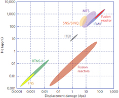
Figure 1. Graph showing the correlation of dpa versus appm of He generated for the different existing possibilities of testing materials (alternative and International Fusion Materials Irradiation Facility (IFMIF)) compared with fusion reactor conditions [1]. Reprinted by permission from Macmillan Publishers Ltd: Nature Physics [1], Copyright 2016.
Download figure:
Standard image High-resolution imageUnderstanding the degradation of structural materials subjected to a high fluence of fusion neutrons is indispensable for the safe design of a fusion power reactor as a pre-condition to receiving the license for operation from the corresponding nuclear regulatory agency. Thus an essential step, which is part of current fusion roadmaps, is to remedy the historical deficiency and to build and operate a fusion-relevant neutron source for materials' testing.
2. The IFMIF/engineering validation and engineering design activities (EVEDA) project
An assessment of possible solutions for a neutron source suitable for fusion materials testing concluded in the early 70s that Serber's deuteron stripping reactions [9] in liquid Li would be the best possible candidate. The seminal proposal towards a fusion-relevant neutron source based on Li(d, xn) nuclear reactions was published in 1976 [10] and as early as 1979, the first review of the state-of-the-art of the underlying technology concluded that such a neutron source is indispensable to validate and calibrate the existing neutronics models [11]. The diversity of key parameters (neutron flux, spectrum, fluence, irradiation temperature, mechanical loading conditions, microstructure, thermo-mechanical processing history, lattice kinetics etc) can only be found out unambiguously by experiments with fusion-relevant neutron sources. A thorough understanding of the physics underpinning the interaction of the fission neutrons with materials, in combination with modern computing capabilities, has enabled the development of accurate models [12]. These models have led to the optimization of suitable materials through simulations; however, the more complex physics involved with the harder fusion spectrum neutrons jeopardizes this capability to cope with fusion materials' needs [13]. Data accumulated from the vast network of experimental fission reactors (combined with results from spallation sources and clever ion implantation techniques) allow materials scientists to speculate that up to around 30 dpa of displacement damage, the behaviour of the suitable structural materials available today (namely, reduced activated ferritic-martensitic steels) could follow that observed during the operation of fission reactors (see figure 2). Thus, the damage of the materials of the in-vessel components induced by the fusion neutrons during ITER operation—without substantial swelling driven by the limited He atoms accumulated—allows its licensing.
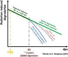
Figure 2. Qualitative comparison of the known degradation of the physical properties of irradiated materials with the degradation assumed for materials exposed to fusion neutrons [14]. Reproduced courtesy of IAEA. Figure from [14]. Copyright 2017 IAEA.
Download figure:
Standard image High-resolution imageHowever, a neutron source with a suitable flux and spectrum becomes an indispensable facility to establish the design basis and to construct any fusion reactor subsequent to ITER, where its aforementioned expected damage level of 3 dpa will be attained within a few months of operation.
The technical challenges of a Li(d, xn) neutron source are enormous since such a facility requires an accelerator to operate under an unprecedented current and average beam power. It also needs to have a Li loop that forms a Li screen with a stable surface in the deuteron footprint; radiation resistant equipment housing reliable specimens at a uniform temperature in a limited volume under a pre-set, tightly controlled temperature, and remote handling (RH) equipment suited to an annual replacement of the hardware exposed to the neutron flux (including the backplate wall channelling the liquid Li). The technological difficulties were found to be insurmountable in the 1980s [15]; the need for a fusion-relevant neutron source led to the iterated organization of international committees to explore alternative ideas [16–18]. Beyond the exoticism of some of these, all new ideas presented serious technical flaws, and the international consensus on the suitability of the Li(d, xn) source was systematically achieved.
The genealogy of a Li(d, xn) fusion-relevant neutron source has already been detailed elsewhere [19]. Since 1994, the IFMIF is the reference concept within the fusion community. The IFMIF/EVEDA project is one of three projects defined in the Broader Approach (BA) Agreement between the Japanese government and EURATOM, which entered into force in June 2007. The specific IFMIF/EVEDA annex in the BA Agreement mandates the project to produce an integrated engineering design of the IFMIF and the data necessary for future decisions about the construction, operation, exploitation and decommissioning of the IFMIF, and also to validate the continuous and stable operation of each IFMIF subsystem. Thus, the IFMIF/EVEDA project consists of two parallel mandates: the engineering design activity (EDA) [19] and the engineering validation activity (EVA) [20].
The success of the IFMIF in both concurrent EDA and EVA phase mandates will be detailed in this article. In particular, the ongoing successful validation of the technological challenges of the Accelerator Facility (AF), the Li Target Facility (LF) and Test Facility (TF), of which the findings are integrated into the engineering design proposed in the accomplished EDA phase, is allowing decisions soon towards the construction, possibly to start this decade, of a Li(d, xn) fusion-relevant neutron source [21].
2.1. EDAs
The IFMIF will generate a neutron flux with a broad peak at 14 MeV, mainly through Li(d, xn), stripping reactions thanks to two parallel 125 mA continuous wave (CW) deuteron accelerators at 40 MeV colliding with a footprint of 200 mm × 50 mm in a liquid Li screen. The 250 °C Li target will be flowing at 15 m s−1 with a stable thickness of 25 ± 1 mm to fully absorb and evacuate the 2 × 5 MW beam power (Bragg peak of deuterons at 40 MeV in Li is 19 mm). The 40 MeV energy of the beam and the 2 × 125 mA current of the parallel accelerators has been tuned to reach a comparable neutron flux (1018 m−2 s−1) to the one expected in the most exposed structural materials of a fusion power reactor. An irradiation volume of 500 cm3 will contain 12 cooled capsules each housing around 2 × 40 small specimens for a total of more than 1000 specimens. Each capsule can be individually cooled at a target temperature ranging 250 °C < T < 550 °C with the specimens presenting a ΔT < 3% (K) during irradiation. The neutron flux provided and the design of its high flux test module (HFTM) containing the 12 capsules impacted by the deuteron beam allows >20 dpafpy per year of operation at fusion-relevant conditions. The test cell (TC) is designed to also house a middle and a low flux test module (LFTM) for higher volumes but lower dpafpy capabilities. The IFMIF will enable 30 years of operation.
A detailed description of the IFMIF construction is published elsewhere [19], nevertheless a summary of the design follows for a complete picture of this overview.
The IFMIF plant is composed of five specific facilities. Accordingly, the systems designed for the IFMIF plant are grouped into the AF, the Li target facility (LF), the test facility (TF), the post irradiation examination facility (PIEF) and, the conventional facilities (CFs). The latter group of systems ensures power, cooling, ventilation, rooms and services to the other facilities and itself. An bird's-eye view of the IFMIF is available in figure 3.
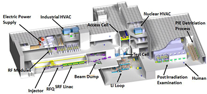
Figure 3. Artistic bird's-eye view of the IFMIF's main building.
Download figure:
Standard image High-resolution imageThe accomplishment of the EDA phase in June 2013, exactly within the six years allocated, is intimately linked with the present findings obtained by the validation activities, which although were ongoing at the time of the release of the report, allowed the definition of the design to be consolidated by the construction and operation of prototypes [20]. The report released is composed of five major elements: (1) the 'executive summary'; (2) the 'IFMIF plant design description' (PDD), which summarises the content of more than 100 technical reports; (3) a careful cost and schedule report, based on the experience gained with the construction of prototypes during the EVA phase and the analysis of recognised Japanese and European engineering companies; (4) annexes to the PDD; and (5) 34 detailed design description documents (DDDs) of all the sub-systems supporting the PDD. A list of all the documents generated is available in figure 4. The first two documents listed below, the Executive Summary and the IFMIF plant DDDs) have been widely distributed in a handy booklet.

Figure 4. List of documents produced in the EDA phase.
Download figure:
Standard image High-resolution imageA careful description of the design has been published in the Nuclear Fusion journal [19].
Various improvements in the design have been implemented during the EVEDA phase, the most relevant ones being [22]: (1) the Alvarez-type drift tube linac (DTL) in the AF has been replaced by a superconducting radio-frequency (RF) linac, and consequently the RF system has been simplified accordingly (with a substantial reduction in the future facility operation cost); (2) the configuration of the TC evolved as in the present design, where the irradiation modules no longer have a shielding function and are thus detached from the shielding block, which improves the irradiation flexibility and the reliability of the RH equipment (and also reduces its costs); (3) the quench tank (QT) of the Li loop, previously inside the TC, has been relocated outside reducing the tritium production rate and simplifying the maintenance processes; (4) the maintenance strategy together with the management of the irradiated samples has been modified to allow a shorter yearly stop of the irradiation operations.
The main building (see figure 3) is a four-storey rectangular building which has a dimension of about 137 m in length, 111 m in width, 40.5 m in height (27 m high above ground level). The main building contains the AF, LF and TF systems and the plant services of the CFs. The TC that houses the target assembly (TA) and the test modules (TMs) is a blind hot cell (4 m long in the beam direction, 2.8 m wide and 4 m deep) with a unique opening at the top. This opening is closed during irradiation periods by two concrete shielding plugs (SPs) 2.5 m high in total. The inner walls of the TC are covered by a closed steel liner [23].
The availability goal for the IFMIF is 70% over the calendar year, which together with its specifications regarding damage rate in iron (>20 dpafpy in the high flux region) is directly linked to the main mission of the IFMIF. The irradiation cycle is established in 11 months, mainly based on the lifetime expectations for the TA. This is broken down into one long maintenance period of 20 d for general maintenance (mainly in the TA and TMs replacement) and long-term accelerator maintenance, and another intermediate maintenance period of three d for short-term maintenance activities in the accelerator and other ancillary and conventional systems.
RAMI analyses have been performed in order to identify critical components and to develop strategies to reduce downtimes and increase reliability. They have assessed the components' design and they have allocated the desired availability to each sub-system so that the high availability requirements have been met successfully. Detailed analysis of the different facilities has led to high reliability and maintainability design evolution, and has brought up design proposals that once implemented have demonstrated their effectiveness towards realizing the IFMIF goal.
Taking into account the scheduled maintenance time, the operational availability requirement of 70% over the calendar year is translated into an inherent availability requirement of 75% over the 11 months of scheduled operation time. This inherent availability requirement, allocated among the facilities, can be seen in table 1.
Table 1. Inherent availability requirements for the facilities at the IFMIF facilities.
| IFMIF facilities (and systems) | Inherent availability (%) |
|---|---|
| AF | 87 |
| LF | 94 |
| TF | 96 |
| CFs (excluding central control system and common instrumentation) | 98 |
| Central control system and common instrumentation | 98 |
| TOTAL (product) | 75 |
Generally, RH is adopted to prevent the radiological exposure of personnel during maintenance operations as well as during experimental activities [24]. When the radiation field is above the hands-on limit of the radiation protection guidelines of the ICRP60 (i.e. > 10 µSv h−1), different approaches can be used in function of the dose rates expected in each area: use of RH technologies, use of local shielding, maintenance performance by workers on shift or otherwise waiting until the dose decreases sufficiently. Some IFMIF components require regular and scheduled maintenance, such as during the annual long shut down, as well as replacements in case of failure.
2.1.1. The Accelerator Facility.
Each of the two symmetric linacs of the IFMIF (see figure 5) will produce deuteron beams of 125 mA in CW at 40 MeV for a total of 2 × 5 MW beam average power [25]. The ion source implements the 2.45 GHz and the 875 Gauss electro-cyclotron resonance concept developed by Chalk River [35] at 140 mA and 100 kV with a five electrode beam extraction system. The extracted beam is matched to the radio frequency quadrupole (RFQ) entrance thanks to a dual solenoid focusing scheme; in turn, the transverse emittance values at the output of the LEBT shall be <0.3 π mm·mrad [37] and 95% D+ fraction to ensure a transmission >90% at the 5 MeV output of the RFQ.
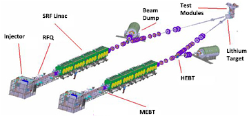
Figure 5. Three-dimensional (3D) layout of IFMIF accelerators.
Download figure:
Standard image High-resolution imageThe RFQ follows a four vanes design accelerating the beam to 5 MeV along its 9.7 m length. The shortcomings at low energies when handling high currents due to space charge effects led to choosing the high input energy of 100 keV with the aforementioned challenging emittance values that will keep losses below 10% until the end of the 'gentle buncher', and below 10−6 in the high energy part (activation by deuterons, with significantly higher activation cross-sections than protons, will be within the hands-on maintenance limits) [26]. The active tuning of the RFQ during operation in CW will be achieved following the dual tip/vane cooling approach successfully developed in the 90s for LEDA's RFQ [27].
Five quadrupoles and two consecutive five-gap cavities bunchers in the MEBT designed at CIEMAT, fulfil the transverse and longitudinal matching conditions of the RFQ output beam to the superconducting RF cryomodule (SRF linac) under the control of the low level RF. Two movable scrapers capable of withstanding up to 500 W will stop the beam halo and out-of-energy particles coming from the RFQ.
The SRF is a ~22.7 m long linac, consisting of four consecutive cryomodules. The acceleration of the beam is made by superconducting half-wave resonators (HWRs) with a two-gap cavities configuration at 175 Hz and 4.5 MV m−1 accelerating voltage. The frequency of the HWRs is adjusted precisely by a traditional mechanical tuner (range +30 kHz, resolution 200 Hz). The beam focusing and orbit corrections are performed by sets of superconducting solenoids/steerers and beam position monitors, located before each HWR. The cryostat maintains the superconducting elements below 4.5 K, keeps its internal components under an insulation vacuum and insulates them from ambient temperature, pressure andEarth's magnetic field.
The objective of the HEBT line is to transport and properly focus the 40 MeV beam coming out from the SRF linac in order to achieve a beam footprint at the liquid Li target with (a) a rectangular shape of 200 mm × 50 mm on the flat top, (b) uniformity of the beam density across the flat top within ±5% and (c) horizontal beam density lower than 0.5 µA cm−2 beyond ±11 cm. These three conditions are practically achievable through non-linear multipole optics.
2.1.2. The Li Target Facility.
The LF, with its 9 m3 of Li, provides and conditions the Li screen serving as beam target, which presents two main functions: (a) a reaction with the deuterons to generate a stable neutron flux in the forward direction and (b) a dissipation of the beam power in a continuous manner [28]. It is broken down in: (a) the target system, which consists of components situated in the TC, and then the beam ducts up to the target interface room; (b) the heat removal system, which consists of the main Li loop and its dump tank; (c) the impurity control system, which consists of a branch line that extracts a fraction of the Li from the main loop and re-injects it after purification; (d) the maintenance system, and (e) the ancillary systems, which are comprised of the control system, the gas supply and exhaust system, the vacuum system, the leak detection and recovery system and the electric power system [29]. A 3D view of the LF is shown in figure 6.
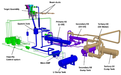
Figure 6. Layout of the target facility.
Download figure:
Standard image High-resolution imageTo efficiently fulfil both functions, the LF needs to provide a stable target geometry to the deuteron beam to completely absorb the 10 MW average beam power from both accelerators and protect the thin reduced activation ferritic-martensitic (RAFM) steel backwall plate that channels it. The liquid Li is shaped and accelerated in the proximity of the beam interaction region by a two-stage reducer nozzle to minimize the transverse velocities components aiming at a laminar flow. In turn, in the beam footprint area, a concave jet of 25 mm thickness with a minimum radius of curvature of 250 mm, builds a centrifugal acceleration of 90 g; this compression raises the boiling point of the flowing Li guaranteeing a stable liquid phase in Bragg's maximum heat absorption regions (Bragg's peak of deuterons at 40 MeV in Li is around 19 mm) [28]. The free surface stability (±1 mm tolerance is specified) and the adequate jet thickness allows the deuteron beam to be safely stopped and the fluctuations of the neutron flux in the test specimens to be limited (the HFTM [29] is situated at a 2 mm nominal distance of the thin backwall plate channelling the Li).
The heat removal system is designed to remove the heat deposited by the beams in the target and maintain a defined Li temperature and flow rate at the TA inlet. It has the flexibility to operate also at intermediate power levels, and it must also be capable of managing transients during beam start-up or shutdown and trips of one or two accelerators. The nominal inlet temperature at the TA is set to 250 °C. The heat deposited by the beams raises the flowing Li temperature to 298 °C. The heat removal system of the main Li loop circulates the 97.5 l s−1 Li flow from the exit of the beam target to a 1.2 m3 QT, where it is slowed down and thermally homogenized before it flows to the electromagnetic pump. The Li is then cooled back to 523 K by a series of heat exchangers.
The impurity control system in the Li will be done through tailored design cold and hot trap systems; purities of Li during operation better than 99.9% are expected. The presence of impurities in the flowing Li have not only implications on nuclear safety given the radioactive by-products of the Li(d,xn) nuclear reactions but might also have an effect on the free surface stability (the presence of gases as well of solid elements in suspension might favour the nucleate boiling). The impurity control system consists of a branch line, which extracts a fraction of the Li from the main loop and re-injects it after purification and impurity analysis. The system is designed to condition the Li after maintenance prior to start-up and control and maintain a defined level of purity. The purification branch contains: (a) cold traps to collect impurities with temperature-sensitive solubility, such as O, C, Be and other corrosion products within 10 wppm; (b) hot traps to specifically capture N chemically within 10 wppm, and (c) hot traps to extract tritium within 1 wppm by specifically binding all H isotopes chemically within 10 wppm. A corrosion limit of about 1 µm yr−1 has been set for the backwall plate and 50 µm in 30 years in loop conduits. This requirement is assumed to be achieved by limiting the flow velocity and Li temperature and by controlling and maintaining the chemistry within defined tolerances (in particular the N content, which drives corrosion in steels exposed to flowing Li) to limit the corrosion/erosion of the structural materials and the dissolved nuclear inventory. In turn, deuteron and neutron interaction with Li generates radioactive products, essentially tritium and 7Be impurities and dissolved corrosion products, which become activated when transported through the beam footprint. Limiting the nuclear inventory in the Li in view of accident mitigation and managing the distribution of gamma-emitters is required to assure accessibility to the loop area during maintenance operations [30].
2.1.3. The Test Facility.
The TF [23] includes the systems required to accommodate the TMs under a controlled environment and conditions for irradiation, as well as all the systems required for their assembly and disassembly and submission of the irradiated specimens to the PIEF. The TF comprises all equipment, primary heat removal systems, purge gas systems and handling facilities for an accurate and safe positioning and handling of specimen, modules, and target during beam operation and maintenance. It consists of the TMs, the TC, the access cell, TM handling cells, TF ancillary systems (TFASs), and RH systems (the TFASs are also known as TF utility rooms in reports of previous IFMIF phases). Figure 7 shows the 3D view of the TF design in the IFMIF plant.
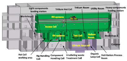
Figure 7. The arrangement of the TF in the IFMIF main building.
Download figure:
Standard image High-resolution imageThe main missions of the TF are: (a) housing the Li(d,xn) reactions; (b) disassembling and assembling of the TM including insertion and extraction of specimens; (c) replacement of TA and TMs, and (d) transportation of the specimens between the TF and the PIEF. The maintenance system is shared between the TF and the LF. The TF will provide standard RH systems to remove and insert the LF components (mainly the TA and Li pipes) while the design of the LF includes the specific tools for those RH procedures like the bayonet backwall plate. The two key spaces of the TF are: (a) the TC housing the TMs and (b) the set of hot cells allowing the replacement of the TA and the TMs, the preparation of new modules and the extraction of irradiated specimens.
The TC is a blind hot cell with an opening at the top [31] (see figure 8). The surrounding shielding walls are riveted with a liner which provides, together with the TC upper cover plate, a vacuum tight enclosure to guarantee that an inert atmosphere is maintained during beam operation with a negative ΔP. The liner and biological shielding (BS) are made from concrete and cooled with chilled water. The TC structure serves as a checkpoint for the orientation or fixation of the TC internals in relation to the beam axis. The BS of the TC is completed by the SPs. The top closure of the TC is split into two top SPs. The connections between the TC and the external world for transferring liquids, gases or signals are made through the piping and cable plugs (PCPs).
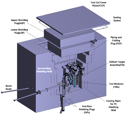
Figure 8. TC with internals and penetrations for beam tubes as well as Li loop inlet and outlet pipes.
Download figure:
Standard image High-resolution imageThe TMs are supported from the TC walls, which are parts of the BS allowing their independent operation. The final tightening of the TC is achieved by the TC covering plate (TCCP). It closes the TC over the SPs. The cover sheet and in particular the sealing against the liner is outside the high dose radiation field. Liner and cover are designed for an inner sub-pressure of 1 mbar. The free volume of the TC cavity and the entire volume of all gas/helium loops connected to the TC are related in so far as no over pressure of the TC may occur in the case of a leak. In addition to that, an over pressure design is excluded.
Three different irradiation areas are foreseen behind the backwall plate in the TC for TMs' installation: the high flux test (HFT) region, the medium flux test (MFT) region, and the low flux test (LFT) region [32] (see figure 9).
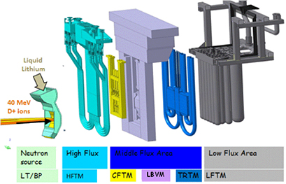
Figure 9. Target and TMs arrangement in the TC—the neutron cloud and the TMs are shown symbolically.
Download figure:
Standard image High-resolution imageTwo different module concepts have been defined in the HFT region: (a) the HFT module vertical layout (HFTM-V) and the HFT module horizontal layout (HFTM-H), which are expected to be arranged inside the TC in different irradiation campaigns. Three different modules have been designed for the MFT area: (a) the creep fatigue test module (CFTM) [33], (b) the tritium release test module (TRTM) [34] and (c) the liquid breeder validation module (LBVM) [35]. Also, neutron spectral shifters could be installed. It is to be noted that these three modules cannot be simultaneously located in this area and different configurations will be used in the different irradiation campaigns. The LFT area is capable of housing several containers in which different experiments can be performed accommodated in the LFTM. Last but not least, a start-up monitoring module, only used during the commissioning phase of the IFMIF, is also included in the TF [36].
The HFTM-V (see figure 10) is dedicated to the research on RAFM steels, to be tested in the temperature range 250–550 °C, with an option to provide irradiation up to 650 °C for ODS steels [37]. The uncertainty of temperature for 80% of the specimens will be below ±3% (K) thanks to an individual cooling per compartment and especially the zonal heater system in the capsules, thermocouples and temperature homogenization of the specimens by filling the capsules with NaK-78 eutectic alloy. To measure and to control the irradiation temperature, up to three to six type-K thermocouples will be located inside the specimen stack. The thermocouple readings are the input to the control of the capsules' electric heaters. In addition, the specimens can be cooled from their current temperature to below 200 °C within 15 min after the irradiation to avoid mitigation of the irradiation effects by annealing. The arrangement of the specimens in the HFTM is adapted to face the 200 mm × 50 mm beam footprint of the neutron source. The specimen positioning and the dimensioning of reflectors are conceived to limit the neutron flux gradient to less than 10% of the individual sample's gauge volume. The HFTM-V is built from a thin walled container divided into eight compartments, into which three rigs can be placed (a total of eight × three rigs). Small specimens arrange in the central four compartments which can house around 1000 in a total of four × three capsules, where neutron flux gradients and flux levels are suitable for high-quality irradiation experiments [38]. The remaining four (two × two) side compartments are also filled with rigs, but their function is mainly to act as lateral neutron reflectors and accommodate instrumentation, like fission chambers for online flux monitoring. It is to be noted that in these lateral compartments, the neutron flux amounts to only about 10% of the central positions, but the gradients are low, and can thus be attractive as additional irradiation space [39].
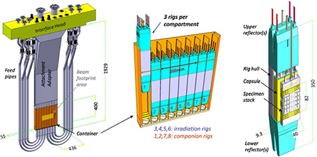
Figure 10. Design overview of the IFMIF HFTM showing assembly, compartments, irradiation rigs and capsules filled with arranged small specimens.
Download figure:
Standard image High-resolution image2.1.4. PIEF.
The PIEF will mainly perform post irradiation tests and examinations of the irradiated specimens to generate the essential material database [40]. The PIEF will provide the capability to conduct mechanical properties and metallographic properties on irradiated materials, and it will also have the ability to characterize the fracture surfaces after test failures [41]. It will allow the long-term storage of irradiated material for further future analysis. As a main assumption of the functional definition, the PIEF must be able to perform in one year the post-irradiation examination of all specimens for four of the rigs set in the HFTM, and in three years all tests of the specimens for all 12-rigs of the HFTM. The list description and capabilities of other PIEFs all over the world as summarized by the IAEA [42] has been used as the design reference.
The PIEF is placed in a wing of the main building to minimize the handling operations of irradiated specimens. Its layout can be seen in figure 11.
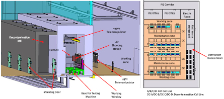
Figure 11. Left: two-dimensional layout of the PIEF. Right: isometric view of a line of the hot cell laboratory.
Download figure:
Standard image High-resolution image2.1.5. The CFs.
The design of the CF comprised of buildings, site infrastructures, and plant services has been carried out with the support of the engineering services of a specialized industry in Japan and Europe [43]. The layout and the corresponding 3D models were developed based upon a comprehensive analysis of the functions and implantation of the different rooms, the description of the whole plant and of each room (including materials' flow, access routes, handling, lift, etc), as well as the main equipment footprints (volume/space reservation) and routing plans of main heating, ventilation and air-conditioning (HVAC) ducts, pipes and cable trays under nuclear requirements [44]. The objective was to allow the management of the IFMIF plant 3D models from the onset and all along the design process by continuously cross-checking the clearance and potential interferences to eventually allow for a complete integrated model of the IFMIF plant and the different systems/facilities inside the building.
The breakdown of the IFMIF plant services includes: (a) the HVAC system (both industrial and nuclear); (b) the heat rejection system; (c) the electrical power system; (d) the service water and service gas system; (e) the radiation waste treatment system (including both solid and liquid waste as well as a complex exhaust gas detritition system); (f) the fire protection system; the access and security control system; and (g) the radiation monitoring system. The design of each system was developed progressively; firstly by establishing a sound design basis starting from a system functional description. This was followed by the identification of the corresponding interfacing systems and the technical requirements imposed by them, and ended with the definition of the process flow diagrams and basic equipment layout. Once the technical requirements were identified and the design basis established, the systems design was further developed. Piping and instrumentation diagrams, key-one line diagrams, and the equipment list for the different systems, as well as a layout plan of the main equipment and routing of ducts, piping, and cable trays, were defined and eventually integrated into the 3D model of the building.
2.2. EVAs
The validation activities aimed at demonstrating the feasibility of the continuous and stable operation of each IFMIF sub-system [20, 21]. The EVA phase was developed in parallel with the EDA phase, which was also supported with thorough RAMI analysis to ensure the nominal availability. The design of the IFMIF incorporated the lessons learnt during the EVA phase, among which the construction of the following hardware detailed below deserves to be highlighted:
- an accelerator prototype (LIPAc, acronym standing for linear IFMIF prototype accelerator) at Rokkasho, fully representative of the IFMIF low energy (9 MeV) accelerator (125 mA of D+ beam in CW mode) [45, 46];
- a Li experimental loop (ELTL, acronym standing for EVEDA Li test loop) at Oarai, basically 1:1 scale, operating at the IFMIF nominal conditions [47, 48], and
- corrosion/erosion experiments with IFMIF Li loop relevant conditions in LiFus 6, the Li loop constructed under the EVEDA phase at Brasimone [49] (see figure 12).
- The HFTM full scale prototype [50], including its capsules filled with small specimens, tested in the helium loop HELOKA [51]. Capsules of the HFTM in its vertical and horizontal concept irradiated in the experimental fission reactor BR2 of Mol [50].
- Small specimens test techniques for fatigue, fracture toughness and crack growth [52].
- The CFTM [33] manufactured and tested in full scale at Villigen.
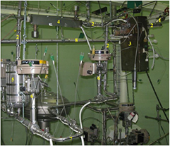
Figure 12. View of Li loop LiFus 6: (1) regulating valve (connected to the main loop); (2) purification loop pipe; (3) resistivity meter; (4) air cooler upstream of the cold trap; (5) cold trap; (6) pneumatic valves to permit/exclude Li circulation in the sampling tube; (7) sampling 'U' tube; (8) pipeline of the main LiFus 6 loop.
Download figure:
Standard image High-resolution imageAn extensive overview paper [21] addressed the EVA phase of the IFMIF and it is not repeated here. It is however important to understand the maturity of the concept and the outcomes of the ongoing EVEDA and perspectives to allow decision making regarding the potential construction of a Li(d, xn). This will be addressed in the following section.
3. The technological maturity of a Li(d, xn) concept being assessed by the IFMIF/EVEDA
The decades-old endeavours towards overcoming the challenges of a Li(d, xn) have demanded breaking through technological frontiers in different fields such as accelerators technology, liquid metals and mechanical engineering. The underlying technology was not ready in early phases of the program. This was learnt in FMIT in the early 80s when insurmountable difficulties were faced in terms of operating an accelerator as initially specified [53] (deuterons at 100 mA in CW at 35 MeV) to reach the suitable 14 MeV neutrons fluence in testing specimens within a reasonable testing time. It has only been 25 years later, during the ongoing IFMIF/EVEDA project, that successful efforts to demonstrate the feasibility of a Li(d, xn) have been developed with the construction of hardware validating the nominal operational conditions. In this section, details of this maturity will be provided which address the main historical, technological concerns related to the feasibility of the IFMIF; these have been identified as:
- the feasibility of a 125 mA CW deuteron beams at 40 MeV;
- the long-term stable operation of the 25 mm thick Li flowing at 250 °C and 15 m s−1 with fluctuations in the surface within ±1 mm;
- the stability of the Li screen absorbing the 2 × 5 MW beam power during operation;
- the feasibility of irradiating the small specimens under a uniformity of temperature within ±3%;
- the validity of data retrieved from small specimens; and
- the corrosion phenomena in steels induced by flowing Li.
3.1. Feasibility of a 125 mA CW deuteron beams at 40 MeV [45, 46, 54]
The required unprecedented performance of the IFMIF with its 125 mA CW deuteron beam at 40 MeV leading to 5 MW beam average power necessitated its validation with a prototype. The linear IFMIF prototype accelerator (LIPAc), designed and under construction in European labs and under installation and commissioning in Rokkasho Fusion Institute, matches the design of the IFMIF up to its first superconducting accelerating stage with 9 MeV beam energy (see figure 15) [45, 46]. Collective phenomena driven by space-charge forces become the main limitation to achieving high-intensity beams. In low β-regions, the radial outward Coulomb forces prevail in the beam over the inward radial Ampere ones, which mutually cancel in the relativistic domain. Thus, space charge repulsive forces are the more dominant, the lower the beam energy is. The successful operation of LIPAc at 9 MeV in CW downstream the first cryomodule will validate the IFMIF's accelerators (see figure 13).
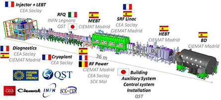
Figure 13. Breakdown of the contribution for LIPAc, presently under installation and commissioning in the International Fusion Energy Research Center (IFERC) in Rokkasho (Japan) under the joint coordination of F4E and QST.
Download figure:
Standard image High-resolution imageThe FMIT project, in the US in the early 80s, heralded the start of modern accelerator driven systems (ADSs) [11]. These could not be conceived technically without the invention of the RFQ in 1969 by Teplyakov and Kapchinsky [55], which efficiently bridged the keV energy beam ranges from the ion source to a few-MeV energy. The 70 year-old Alvarez type DTL approach demands drift tubes with increasing lengths proportional to β. Furthermore, the focusing strength of the magnetic fields is driven by Lorentz forces. Thus for low-β beams quadrupole focusing in DTLs is not efficient and the integration of equipment cumbersome. In turn, at energies >100 MeV, the effective shunt impedance starts to decrease, becoming less effective than other accelerating structures. Thus, DTLs are suitable for a narrow beam energy window (0.05 < β < 0.4). The electrical focusing, independent of the particle speed, and pre-bunching capability of the accelerating RFQ structures allowed a major step forward in hadron accelerator capabilities.
The first world attempt for a CW low-β high current H accelerator in FMIT, framed by fusion materials research, taught us the difficulty of the challenge [53]; our technology was not ready. The operation was strongly affected by the cathode-based poorly performing ion sources with two crucial shortcomings: (a) the availability of the cathode and (b) the quality of the beam from its source. The cathode of an ion source is constantly bombarded by ions, which erodes the cathode material, impacting its shape, composition, and microstructure, and rapidly degrading its design performance; this effect is obviously enhanced with high currents and duty cycles. In FMIT, 130 mA of  in CW at 75 keV was targeted as beam input for its RFQ; a poor efficiency in the gas fraction demanded currents above 200 mA through the LEBT—this fact strongly degraded both the vacuum and the beam quality. The FMIT RFQ succeeded in operating to the designed CW field (vane-tip fields of 1.68 Kilpatrick) and accelerated more than 50 mA of
  to full energy (2 MeV) in CW, but for a short time. Thermal expansion decreased the operating frequency by 170 kHz from the start up to full-power operation. Thermal stresses were directly responsible for most of the problems encountered when duty cycles were increased, which were mostly solved by attaching additional cooling lines and by accommodating thermal expansion RF shielded joints wherever possible. Excessive gas loads leading to pressures of 10−5 mbar caused swiftly thermal runaway of ion pumps. Multipacting was also observed with dark areas in various parts of the 4 m long RFQ; which were successfully overcome with TiN coating. A deuteron beam was not used to avoid activation problems under the wrong assumption that
  would behave similarly, however stripping and dissociation of
  led to large neutral and H+ beam halos which damaged output beamline components. In 1984, the project was canceled due to escalating costs [56], driven by the impossibility of reaching the target of 100 mA CW
  at 2 MeV [53].
After FMIT's accelerator failing lessons, it was perceived by accelerators experts as impossible operational conditions those required by a Li(d, xn) fusion-relevant neutron source.
Fortunately, the accelerator know-how has matured in all possible aspects since the time of FMIT's conception in the 1970s; at present, operating a 125 mA deuteron beam at 40 MeV in CW with high availabilities, though challenging, seems feasible thanks to the understanding of the physics behind the beam halo [57] and the following three main technological breakthroughs in accelerator technology:
- the electron-cyclotron resonance (ECR) ion source for light ions developed at Chalk River Laboratories in the early 1990s [58];
- the RFQ operation of H+ in CW with 100 mA demonstrated by LEDA in Los Alamos in the late 1990s [59], and
- the growing maturity of superconducting resonators for light hadrons and low-β beams (typically 0.03 < β < 0.2 [60]) achieved in recent years [61].
In 1991, a technological breakthrough took place with the successful development of the ECR principle for H ion sources, widely used since the early 80s with heavy ions as an injector for cyclotrons. This concept is based on the excitation of a cold plasma by the resonant absorption of microwaves by electrons orbiting in a suitable magnetic field for the production of a high-quality ion beam. Taylor successfully developed such an approach for H+ beam at Chalk River Laboratories [58], and it has been widely used since the early 90s.
The operation of a high current proton beam in CW through an RFQ was eventually achieved in 1999 with LEDA [59]. The RFQ of LEDA accepted a 75 keV, 110 mA DC proton beam from the ERC injector with ~94% transmission. It succeeded to operate in CW for >110 h. No bending magnet for ion fraction separation was present in the LEBT, counting with two solenoids and steerers. A beam matching improvement was achieved by reducing the distance from the second solenoid to the RFQ and the installation of an electron trap at the entrance of the RFQ to prevent electrons from flowing forward, and contributing to the space charge compensation of the beam. The success of LEDA would not have been possible without the lessons learnt with FMIT endeavours, the rough way, almost 20 years before and driven by fusion materials' research. In addition to the thermal stresses and hot spots faced in FMIT, thermal expansion induces a complex impact on resonant frequencies given the combination of capacitive and inductive effects and the enhancement of losses if not adequately tuned during operation. LEDA's RFQ consisted of an 8 m-long resonant cavity at 350 MHz taking protons to 6.7 MeV, with four vanes providing a significantly larger aperture and gap voltage in the accelerating section than all preceding RFQs. The tuning during the operation was achieved with two independent cooling circuits for the capacitive and inductive parts of electrodes. To reduce the beam loss and optimize the needed RFQ length, a large aperture was maintained together with an increase in the vane voltage to counter the decrease in the transverse focusing strength as the vane modulation increased. Insufficient transmission and misleading measurements of current (input current surprisingly less than output current 8 m downstream) were overcome with the addition of an electron trap in the LEBT right before the RFQ entrance and a reduction in the distance from the second solenoid from 30 cm to 15 cm which allowed adequate beam matching and transmission reliably >90%. Unexpectedly high activation values were measured at the high energy end of the RFQ; this gave signs of high beam losses at that location; by operating the RFQ with fields about 10% above the design value, the magnitude of the beam loss was reduced.
The interest in using superconducting structures is usually driven by space optimizations and operational costs, thanks to a dramatic reduction of power consumption, even considering the needed cryogenic power and cost of helium. Superconducting cavities present surface resistance scaling with ω2, so RF power losses are non-negligible; however, these are several orders of magnitude lower than normal conducting ones. Their theoretical and practical development last 20 years, allowing the present day's consideration of reaching the desired 40 MeV deuteron energies without an Alvarez-type DTL, which would operate in LIPAc possibly under impossible conditions given its inherently poor aperture. The use of superconducting cavities would allow an increase of the beam aperture, with a beneficial impact on beam losses and equipment activation. The demonstration of the feasibility for 0.2 < β < 0.6 proton beams [60] paved the way for a new operational window at even lower β, in a more reliable manner than Alvarez-type-based linacs for high currents. In the existing machines, the most used resonator type is the quarter-wave resonator (QWR), preferred for its relatively low cost, easy mechanical assembly, and high performance at low-β [61]; however, the electric and magnetic dipole field components induced by the asymmetry of its shape, might cause beam undesired vertical steering. The HWR approach is similar to the QWR one, but their intrinsic symmetry cancels the QWR steering effect. This makes the HWR suitable for high current applications with low-β beams, keeping most of the QWR virtues without the main drawback. HWRs also show improved mechanical vibration properties over QWRs [62]. Today, our technology is ready for the challenge: the recent successful operation of protons in CW mode through 176 MHz HWR superconducting cavities up to 4 MeV in SARAF [63] in 2010 with 1 mA and ADS developments in China [64] in 2014 with 10 mA shows the soundness of the way ahead. The conversion into beam thermal energy of free mismatch energy is the cause of the beam halo growth.
In general, in FMIT times the best possible alignment of the equipment handled uncertainties above 100 µm; today alignment with precisions within tens of µm is feasible, which presents a strong impact on beam halo growth mitigation. Thanks to the wider aperture of superconducting structures, the requirements for alignment are less critical. However general alignment and survey precisions are to be typically within 100 µm to mitigate beam halo growth.
LIPAc will become the first of a kind in many technical aspects. The technical design incorporates the best possible technology and available world accelerators' know-how. We aim at operating in CW 125 mA deuteron beam at 9 MeV, validating the 40 MeV since space charge phenomena that lead the accelerator difficulties becomes less and less relevant the higher the energy. Nevertheless, it means a huge step from what has been achieved to date. The implementation of lessons learnt from previous experiences in our design allows us to face the challenge with optimism.
In LIPAc, the ion source, developed by CEA Saclay, implements the ECR concept of Chalk River Laboratories [58] (and has successfully operated in SILHI since 1996 [65]) at 140 mA and 100 kV with a five-electrode beam extraction system. This performance settles the operational point slightly beyond present achievements. Two boron nitride disks protect the entrance of the waveguide and the plasma electrode from ion bombardment and help to mitigate space charge phenomena. The ion source plus its low energy beam transfer is installed and being commissioned at Rokkasho Fusion Institute [66–68] A dual solenoid focusing scheme was chosen to match the RFQ entrance with a transverse emittance value at the output of the LEBT <0.3π mm·mrad. The achievement of 95% D+ fraction with the optimum Twiss parameters would result in a transmission >90% at the 5 MeV output of the RFQ, as per simulations [69]. The compressed 2.05 m long LEBT of LIPAc counts with two solenoids and H/V steerers, presenting a sector valve between them to minimize the distance of the second solenoid to the entrance of the RFQ, where an electron repeller is located. Also, an 8° cone is placed at the entrance of the RFQ to trap the metastable species that will minimize further beam losses in the RFQ.
The RFQ is a four vane structure resonating at 175 MHz with a variable average aperture profile and ramped voltage [70]. It has been designed and constructed in Legnaro National Laboratories of INFN; with its 9.7 m length, it will become the world longest structure, but its target 625 kW beam average power will remain slightly lower than LEDA's. The RFQ is subdivided into three super-modules with the cooling system adapted to this architecture, and the two cooling circuits acting separately in the inductive and capacitive part for each of them, following the tuning approach successfully validated in LEDA for the first time [59]. The resonant frequency is controlled acting on the difference between vane and tank temperature. The shortcomings at low energies due to space charge effects led to choosing the high input energy of 100 keV with the aforementioned challenging emittance values, which will keep losses below 10% until the end of the 'gentle buncher' and below 10−6 in the high energy part [71]. The validation of the tuning and stabilization procedures was established following low power tests on an aluminium real scale RFQ, which determined the mode spectra and the electric field distribution with the bead-pulling technique; this was successfully carried out over summer 2016 in Rokkasho Fusion Institute [72]. The ultra-high vacuum wished performance under beam operation is achieved with cryopumps, profiting from their high pumping capacity for H.
SC technology can be efficiently used in pulsed proton high-power linacs as demonstrated at SNS; it can also be used in CW mode with low-β protons [60] as recently demonstrated [63, 64]. The baseline configuration defined in historical concepts of the IFMIF for the deuteron beam acceleration from 5 to 40 MeV relied on a DTL. The technical feasibility of currents in the order of 100 mA in CW through Alvarez-type structures exhibited possibly insurmountable challenges [54, 73]. The superconducting solution for the accelerator portion of the IFMIF offered two main advantages compared with the more conventional DTL: (a) linac length reduction (~10 m) and (b) electrical power saving (~6 MW) with a positive impact on operational costs [22, 25]. HWRs at 175 Hz and 4.5 MV m−1 were chosen. The resonant frequency of the cavities will be mechanically tuned (range +30 kHz, resolution 200 Hz). The RF couplers provide 200 kW maximum in TW mode to the HWR. The beam focusing and drive are performed by sets of superconducting solenoids/steerers and cryogenic beam position monitors interleaved with the HWR cavities.
Risks linked to uncontrolled beam halo when operating in the 100 mA region were faced dramatically in FMIT, but subsequent experiments with LEDA in 2001 unraveled its origin [57]. Careful alignment of interfacing equipment allowing precisions within 30 µm on the global reference system defined by more than 100 fiducials [74] and a dual beam core-halo matching approach developed under the EVEDA phase [75] will be implemented. To determine the beam halo along the SRF linac, cryogenic CVD μ-loss monitors have been conceived and their feasibility demonstrated by CEA Saclay. We could install three azimuthally on each of the eight solenoids interleaved with the SC cavities. Also, two scrapers with four movable jaws, also interleaved between the first three magnets of the MEBT [76], will stop the beam halo and potential out-of-energy particles coming from the RFQ. Each jaw is capable of withstanding a beam power of up to 500 W (2 kW per scraper). High current and low beam energy have demanded intense non-interceptive diagnostic development [77].
The optimal amplitude and phase stability of the beam is essential for an efficient beam transfer and minimization of beam losses. Microphonics, the changes in cavity frequency caused by coupling to vibration sources from the external world, might be encountered; typically they are enhanced at low frequencies in CW mode [56, 60, 62], but solutions could be implemented upon the identification of the source. The non-relativistic nature of low-β proton beam leads to a higher influence of the cavity field fluctuations driven by phase slippage as the beam traverses the consecutive cavities. The operation in pulsed mode during the commissioning phases and the tuning of the SRF linac will likely become more difficult than CW mode operation due to the transients at the beginning of each beam pulse. Ponderomotive instabilities induced by Lorentz forces on the limited stiffness thin-walled cavities might possibly be encountered; however, a careful design of the RF feedback and the LLRF should eliminate potential problems, even for the pulsed mode operation [78].
LIPAc is under installation and commissioning at the time of writing this article; a 5 MeV beam through the RFQ is expected to be reached during 2017 and a 9 MeV through its superconducting cavities before 2020. A view of LIPAc's status in October 2016 can be appreciated in figure 14.

Figure 14. LIPAc accelerator during its alignment in Rokkasho Fusion Institute at the time of the drafting of this article. From left to right one can appreciate the injector, the RFQ, the MEBT and the diagnostics plate.
Download figure:
Standard image High-resolution image3.2. Long-term stable operation of the Li jet beam target [47, 79]
The Li screen serving as beam target presents two main functions: (1) it reacts with the deuterons to generate a stable neutron flux in the forward direction and (2) it dissipates the beam power in a continuous manner [42]. The impossibility for any known material to be directly bombarded by the deuteron flux for long periods constrains the Li jet to operate with a free surface matching the beam footprint exposed to the vacuum conditions present in the beam line. Furthermore, the jet must also be thick enough to completely absorb the deuteron beam, but also to maximize the neutron flux and available high flux tested volume. Thus the jet and its guiding structural backwall must be kept as thin as possible. The distance of the HFTM to the backplate wall has a strong influence on the neutron flux available for material testing; actually calculations show around a 1% reduction per mm increased distance [80].
The long-term operational conditions of the Li target to ensure the absorption of the 2 × 5 MW deuteron beam are severe. The 25 mm thick Li screen must flow at 15 m s−1 at a temperature of 250 °C exposed to the beam vacuum (the pressure specified on the Li surface exposed to the beam pipe of the accelerator is 10−3 Pa to) with thickness variation driven by potential waves in the surface within +/1 mm. These are considered safe operational conditions given that the Bragg's peak in Li of deuterons at 40 MeV is of ~20 mm. These operational conditions were considered as impossible to achieve by various liquid metals experts.
The ELTL (see figure 15), physically almost equivalent to the loop in the IFMIF plant [81], was built in Oarai and successfully commissioned in February 2011 with a beam target cloning in shape the one of the IFMIF but with a narrower width (100 mm compared to 260 mm for the IFMIF) [82]. The loop consists of three floors with a total height of approximately 20 m including a pit housing the dump tank. The ELTL is composed of two major branches: (1) the main loop with 6''/8'' piping, and (2) the purification control loop with 1'' piping; all made of AISI 304 steel. The main loop contains the TA, a QT, an electro-magnetic pump (EMP), an electro-magnetic flow meter (EMF), a Li cooler and the dump tank.
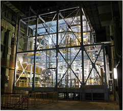
Figure 15. Night view of the ELTL under operation until October 2014 in the JAEA premises of Oarai.
Download figure:
Standard image High-resolution imageThe ELTL holds 5 m3 (to be compared with the 9 m3 expected in the IFMIF) and is able to generate a flow rate of 3000 l min−1, which can produce a flow velocity up to 20 m s−1 in the TA. It can operate at Ar pressure and in a vacuum condition of 10−3 Pa [83]. The TA is installed on the third floor inside an air-tight vessel, which is filled with Ar as backing gas during operation. The TA is equipped with a double reducer nozzle and a flow straightener and it exhibits a concave R250 mm curved open channel of 100 mm in width, generating a free surface Li jet of a nominal 25 mm thickness like in the IFMIF [81].
In September 2012, the loop was back in operation after the damage suffered during the Great East Japan Earthquake, following 15 months of inspection and repair activities.
The purification loop is connected to the main loop at the upstream and downstream of the EMP. An impurity monitoring loop is branched at the downstream of the impurity traps in the purification loop. The purification loop includes a cold trap that removes C and O, and two mechanical interfaces to install two hot traps to remove N and H respectively [84], which were never installed for budgetary reasons. These two hot traps were designed and fabricated in collaboration with Japanese universities, which developed the gettering in a separate task with success for H trapping within the targeted 10 wppm [85], but with controversial results for N purification within the 10 wppm specified. The N content is considered particularly critical, given that it is the main corrosion inducer through the formation of Li–Cr–N ternary compounds. The approach followed of doping with Ti pellets of Fe exhibited limitations to reliably reach the target value due to the formation of impermeable µm thick layers of TiN jeopardizing the diffusion of N [86].
During the last operation campaigns, cavitation phenomena were observed which raised strong concerns. A careful joint study involving JAEA, QST, ENEA and KIT explained both experimentally and theoretically the physical origin. It was located within a few tens of mm coincidence, caused by unexpected Li vaporization induced by a slight misalignment of the downstream pipe, which made an undesired hammer shock in its channelling elbow [87, 88].
In September 2014, during 25 consecutive days the ELTL was operating 24 h d−1 at a 15 m s−1 flow speed and 250 °C. The overlap of 12 measurements of the thickness spanned during this period showed the fulfilment of the challenging requirement of a target thickness stability of 25 mm ± 1 mm (see figure 16) disregarding edge effects [47, 83]. The surface was measured with special developed contact and interferometric tools [89].
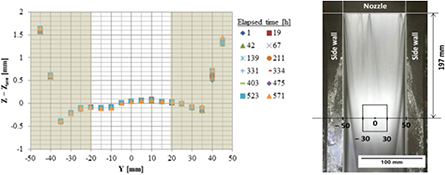
Figure 16. Measurements of surface wave amplitudes along the target width of the ELTL where a stable shape within ±0.5 mm, disregarding edge effects, can be observed during 25 d of continuous operation.
Download figure:
Standard image High-resolution imageIt is important to note that the feasibility of the yearly remote removal of the backplate wall without welding, thanks to the bayonet concept developed in ENEA [90], will allow the achievement of the required tight operational tolerances. Tests on a full-scale prototype with reproduction of the surrounding equipment have obtained good preliminary results.
3.3. Stability of the Li screen absorbing the 2 × 5 MW beam power during operation [28]
The stability of the Li jet during operation has been carefully studied in a continuous manner since FMIT times. The first published numerical study on the subject was produced by Hassberger in 1983 [91],; many other studies [92–94] have been conducted since that time, developing with the evolution of computerized techniques thanks to the application of CFD techniques and various experiments.
The present design, with its 25 mm thick liquid Li screen at 523 K flowing at a speed of 15 m s−1 channelled by a concave backplate wall of 250 mm radius, with a beam footprint of 200 × 50 mm of 2 × 125 mA beam of deuterons at 40 MeV ± 0.5 MeV, results in a power density of 1 GW m−2.
Understanding has been enhanced throughout the years thanks to analysis and experimentation and has resulted in the present design for the IFMIF with:
- a thickness of the liquid Li target of 25 mm sufficient to fully absorb the 40 MeV beam (see figure 17 for operational margins at nominal conditions);
- an operational margin of 41 K in the free surface from saturation temperatures at nominal beam vacuum conditions of 10−3 Pa, which could be increased to 59 K;
- a beam footprint (200 mm × 50 mm) shaped to minimize the thermal response (exposure to beam is limited to 3.3 ms with 1 GW m−2 beam power density on the Li screen, which is about ×10 lower than FMIT's power density [95]);
- a liquid Li speed (15 m s−1) large enough to impede constructive interferences of pressure waves (maximum possible speeds of 0.5 m s−1 from thermal impact or momentum transfer); and at the same time
- sufficient flow to control instabilities;
- a R250 mm concave backplate that increases fluid pressure in Bragg peak hottest regions in the order of kPa leading to saturation temperatures hundreds of K higher than the maximum temperature in the flowing liquid Li; thus, preventing homogeneous nucleation (see figure 17);
- pressure waves amplitudes damped down by centrifugal pressures (32 Pa maximum pressure driven by beam momentum transfer compared with the centrifugal pressures induced by the concave backwall plate in the order of kPa in Bragg's peak regions [28]).
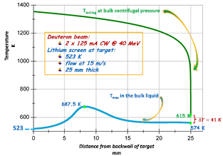
Figure 17. Tmax envelope in the beam footprint under nominal conditions at different depths (in blue) versus Ts corresponding to the centrifugal pressure in the flowing Li (in green). 615 K corresponds to the beam line pressure of 0.001 Pa.
Download figure:
Standard image High-resolution imagePotential instabilities during operation at nominal conditions induced by the interaction of the beam with the flowing liquid Li of the target do not seem possible; potential resonances are mitigated since comparatively high Li flow velocity clears possible constructive interferences. The liquid Li screen will become the beam dump of the IFMIF during its final facility commissioning phases. Further analysis with CFD techniques focusing on the present mature design of the Li target is advisable, though destructive resonances can be neglected.
Vaporization rates are not a concern; a clear understanding of the behaviour has been obtained in specific tests carried out in ELTL [96] overcoming older confusing results [97]. Further, it has been demonstrated that the Hertz–Knudsen–Langmuir equation with η = 1.66 Schrage's accommodation factor is suitable for simple analytical calculations of the expected vaporization phenomena with an assessment for the IFMIF [98].
The available analysis and experiments carried out over the last 30 years has led to the present design of the IFMIF, which prevents potential instabilities in the Li liquid target induced by the two concurrently colliding 40 MeV energy and 125 mA current deuteron beams [28].
3.4. Feasibility of irradiating the small specimens under a uniformity of temperature within ±3% [50, 79]
The HFTM on its own justifies the need of a Li(d, xn) fusion-relevant neutron source. It will allow the irradiation >20 dpa per year of two sets of small specimens characterizing mechanically a given RAFM material at the expected operating temperature in a fusion reactor with an uniformity in the stack of specimens within ± 3%. The unique results will unravel the behaviour of structural materials exposed to high fluences of 14 MeV neutrons. The following requirements have guided the design during the IFMIF/EVEDA phase [50]:
- allow the irradiation of the RAFM steel test specimens in an optimal position to enhance fluence in the projection of the beam footprint area where damages of 20–50 dpa are expected per year of operation;
- control the specimen temperature at defined levels between 250 and 550 °C with a ΔT of the specimen stack in one irradiation capsule within ±3% (K) in 80% of the available volume;
- uniformity of temperature during beam trips shall be ensured to avoid misleading thermal effects in the material degradation;
- optimization of the distribution of the impacting neutron flux to the specimens, with a minimization of flux and spectrum gradients;
- instrumentation capable of learning the desired irradiation conditions (temperature, neutron fluence and spectrum) in the stack of specimens;
- fulfillment of facility requirements: lifetime of one year, structural damage up to 50 dpa;
- specimen payload in the order of 24 batches of each 40 specimens;
- a design which enables assembly/disassembly under RH conditions in hot cells.
A full-scale prototype of the HFTM, the so-called HFTM-DC (with two compartments instead of four as shown in figure 18) was designed and constructed in KIT [50, 37] and tested in its HELOKA loop [51]. The specimens are fit in capsules, which are heated by the Joule effect by conducting current through the surrounding cables. In turn, the capsules are installed in thin-walled irradiation rigs, which allow a thermal insulation gap around the capsules, together with solid metal upper and lower neutron reflectors. The outside surfaces of adjacent rigs together with the compartment walls form an array of parallel mini-channels (gap width 0.6–1.0 mm) allowing the cooling helium flow. Each capsule contains above 80 specimens [38]. Optimal conduction is enhanced by filler pieces in voids of the specimen stack, and remaining gaps were filled up by NaK-78 eutectic liquid metal, which exhibits suitable combined properties of thermal conductivity similar to RAFM steels and a low neutron absorption cross-section. Heater wires are tightly coiled around the capsule wall and brazed for an optimal thermal contact. Thermocouples are installed to allow the control of the desired temperature during irradiation, compensating the nuclear heating profile and manufacturing tolerances impacting the ideal thermal contact with the external cooling gas flow [99].
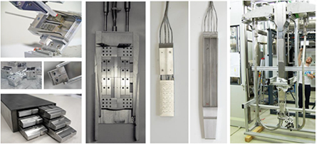
Figure 18. Top left: small specimens during assembly and recovery (NaK coating visible). Bottom left: rigs inserted in the HFTM body. Middle: complete specimen set, capsule, and completely assembled rig. Right: HFTM-DC prototype during integration into the HELOKA-LP helium loop.
Download figure:
Standard image High-resolution imageThe ΔT measured in the stack of small specimens thoroughly instrumented in the prototype rigs assembled in the HFTM-DC tested in the HELOKA-LP complied with the specified target ±3% in 97% of the capsule volume in the temperature range 250 °C < T < 550 °C [23, 50, 79]. Furthermore, three capsules filled with small specimens and thermalized with NaK were irradiated in the experimental reactor of SCK-CEN in Mol [50]. The feasibility of small specimens assembly and disassembly in the capsules (including the NaK handling during filling and unfilling) in a hot cell environment was also demonstrated. Last but not least, the liquid NaK induced potential corrosion on RAFM steels; it was also assessed by exposing specimens to liquid NaK at 500 °C over six months with no observable degradation of mechanical properties, and just a few µm depth measured traces of NaK in the surface of the exposed specimens.
3.5. Validity of data retrieved from small specimens [52, 100]17
Fission neutrons for materials' testing have been available for decades in hundreds of experimental reactors worldwide resulting in an extensive available database. Unfortunately, equivalent experimental fusion reactors for materials' testing do not exist. The development of small size specimens for fusion materials' mechanical characterization started with FMIT in the early 80s, framed by the US fusion program [101], and has continued uninterruptedly since then [102]. The technique has been widely used since the early 60s in fission materials' research with typically 1'' in major dimensions, given that even if the availability of fission neutrons is not in question, the irradiation volumes must also be optimized. Surprisingly, notwithstanding its success in characterizing fission materials, the large database has jeopardized the establishment of an overall normalization with a notorious absence of international standards for small specimens (these are only available for Charpy [103] and fracture toughness through the Master Curve method for ferritic steels [104]). Mechanical properties are intensive; thus they do not depend on the size of the test specimen if a sufficient number of grains across its dimensions are present, which is the case in the mm thickness order given the µm range typical grain size of RAFM.
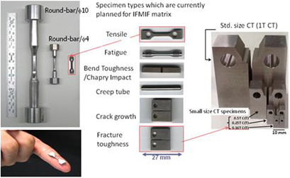
Under the EVEDA phase of the IFMIF, QST (formerly JAEA), in collaboration with Japanese universities and the NIFS, studied the small specimens for fracture toughness, fatigue at the relevant number of cycles of DEMO and ensured fusion power plants, and fatigue crack growth. These were the properties considered to require further development from the existing understanding at the time of the project settling, that in addition to tensile data, impact properties, creep and fatigue crack growth [38, 52] would accomplish the mechanical characterization of a given material at the desired temperature following the irradiation >20 dpafpy expected in IFMIF (with two sets of ~40 small specimens per capsule). Figure 19 shows the shape of the specimens of the agreed test matrix; a 3D model of their potential filling in the capsule together with a picture of the final result can be appreciated in figure 18.
Figure 19. Small specimens defined for the test matrix of the IFMIF that fit in some ~80 in each irradiation capsule (two sets of needed specimens for the full characterization of a given material at the chosen irradiation temperature) [38, 50].
Download figure:
Standard image High-resolution image
A careful explanation of this development campaign and the potential determination of new properties for a future fusion power plant have been detailed elsewhere [52, 100]18. A summary of these results is outlined below.
Fatigue: tests with round-bar type specimens having between ϕ1 and ϕ10 mm showed no size effects (the hourglass flat specimens showed some shortening of life compared with full-size standard specimens due to stress concentrations enhancing crack initiation) [105].
Fracture toughness: specimens with a ¼ compact tension (CT) were tested. The master curve defined in ASTM E1921 developed for ferritic steel pressure vessels of fission reactors  , where KJc is the average fracture toughness and To the test reference temperature at which the median of the KJc distribution from 1'' size specimens will equal 100 MPa·m0.5 showed some divergence for ferritic-martensitic steels. However, a modified version
  seemed to work [106]. Additional work is required to reach a universal expression for RAFM.
Crack growth rate: tests using a H+ charging technique were performed to examine the effect of H ions on crack growth in F82H steel. A small-size specimen with a ¼ CT with wedge opening load steel was developed. The estimated crack growth rate at 30 MPa·m0.5 in water at 288 °C provided suitable data that successfully validated the method [107]. However, slight differences in the results from 1 CT standard size (in particular 0.4 CT and 0.6 CT) were obtained from previous results. The validity of the test specimen is linked to that of the fracture toughness.
The shape defined for the three properties selected showed conclusive results: despite additional tests being required, the shape for the full stack of specimens to characterize RAFM steels mechanically under high fluences of 14 MeV neutrons has been defined [52]. No further iterations on this respect are needed; however, a round-robin exercise between various laboratories is essential to move towards a standardization. Fission reactors did not need this step to convince the corresponding nuclear regulators of their safe design; however the licensing of fusion reactors will be substantially smoothed if international standards are available. The mechanical properties provided by the IFMIF will be undoubtedly accepted by the design engineers for the accomplishment of the design of the DEMO reactor; however the corresponding licensing bodies will inquire about their validity. An efficient use of its operational time is essential. The need for an international drive to merge forces of the various labs around the world working on the subject is shown by the four review papers that have been published since 1983 [101, 102, 108, 109] with more than 10 specific symposia having taken place, mainly organized by ASTM.
Specimens should be prepared by a specific set of procedures which are known to provide consistent test results. An agreement between the testing organization and the user of the test results concerning preparation procedures should be obtained. Coupons from which specimens are machined should either be nominally homogeneous or sampled from the source material, or both, so as to be representative of the properties sought in the application of the material to its end use. Thus, when material requirements allow, specimens should be removed from the same material and product form that will be used in the fabricated component of interest; typically as it is done in most of the high-tech equipment. History of the materials should be traced back, such that any material orientations induced by rolling or casting direction, should be identified with respect to the orientation of the specimen axes. All these issues, exhibiting a clear impact on the mechanical behaviour cannot be left to laboratories' best practices but need to be ruled under defined recognized international guidelines as a first step, and eventually framed by an international standard. This achievement is essential in the development of a fusion materials' database which will facilitate the exchange of information among the fusion materials' community.
Under the coordination of the IAEA, the Coordinated Research Programme 'Towards the Standardization of Small Specimen Test Techniques For Fusion Applications')' [110] was announced on 1st November 2016. Its objective is to develop international standards or IAEA guidelines for all the small specimens of the test matrix designed and defined to fit in the IFMIF irradiation capsules and it aims to be accomplished in a timely manner before the start of the operation of any Li(d, xn) fusion-relevant neutron source.
3.6. Corrosion and erosion phenomena in steels induced by flowing Li [111]
The corrosion induced by alkali liquid metals (namely Na, Li) in steels has been the subject of decades-long intense studies under both nuclear fission and fusion research programs. Liquid alkali metals are excellent coolants due to their wide liquidus temperature ranges (Li exhibits a melting point at 180.54 °C and boiling point at 1347.00 °C), high heat capacity, high thermal conductivity combined with low vapour pressure and high surface tension, which for identical flow parameters, enhances heat transfer coefficients. Other distinguishing features of alkali liquid metals include their high heat of vaporization, low viscosity and density; these factors allow their use in power engineering equipment at high temperatures and low pressure, thus alleviating the solution of mechanical strength problems and enhancing thermal efficiencies [28, 112–114]. Whereas Na is the coolant chosen for fast fission reactors due to its low neutron absorption cross-section and poor moderator properties that optimize hard neutrons availability, Li—or its eutectic Pb–17Li—is the choice for fusion blankets due to the tritium breeder potential of Li. Corrosion phenomena is enhanced at high temperatures, where both the solubility of the alloying elements of the structural materials in Li, and the chemical reactions' kinetics are exponentially increased as per an Arrhenius expression.
In the absence of non-metallic impurities influencing the corrosion phenomena thanks to their efficient purification below chemical reaction equilibrium threshold values, and under liquid metal stagnant conditions, two consecutive processes would take place: (a) the dissolution of metallic elements into the liquid in contact with the boundary materials (the only variables in this process would be temperature, alloying elements and their solubility in the liquid), and (b) the diffusion of solved materials into the liquid medium. However, in the presence of non-metallic impurities above defined concentration thresholds, corrosion is enhanced by the formation of stable oxides, carbides or nitrides whose kinetics can be very fast if suitable conditions take place. Furthermore, for non-stagnant scenarios, corrosion is strongly enhanced mainly driven by mass transfer phenomena due to the temperature gradients in the loop.
The inherent difficulties of all kind of tests trying to unravel the kinetics of alkali metals need to be stressed. We need to remember that aspects taking place concurrently include: (1) challenging and dangerous handling of Li; (2) weight measurements in the order of µg and dimensions in the order of µm: (3) the need to determine species often in quantities below available equipment sensitivities, and (4) not fully understanding mechanisms. The combination of these scenarios is the reason behind the divergence of results that one can find in the literature, leading to the unfortunate remaining uncertainty about physicochemical kinetics where Fe is involved. This has led to a confusing divergence of results available in the literature. However, the understanding of the corrosion phenomena related with flowing Li up to 873 K, typical maximum temperatures of hot trapping techniques, is mature [113, 115, 116]; as well as the physicochemical kinetics involved with the depletion of Cr [117–120], which experiments have shown to be the corrosion driver. In turn, concerning the future uses of Li in the world fusion programme, the most mature understanding is related with 40 year old technological efforts framed by a Li(d, xn) fusion-relevant neutron source. The 2 × 5 MW beam power impacting on a Li screen flowing at 523 K to generate the desired neutron flux will produce an increase of its temperature up to 164 K (see section 3.3) [28]. To prevent the known corrosion enhancement caused by the presence of N in Li, that depletes Cr through a Li–Cr–N ternary compound, it is expected to remove this non-metal by 'hot trapping' at 823–873 K below 10 wppm (see section 3.2) [21].
The allowable corrosion rate in the RAFM backwall plate of the IFMIF that is channelling the flowing Li in the concave region where the D+ beam impacts (which will be replaced every year; something which has been already demonstrated, as explained in section 3.2), has been specified as 1 µm yr−1. The allowable corrosion values of all the other piping exposed to the flowing Li, typically of stainless steel, is set at 50 µm/30 year [21]. To minimize the impact of non-metallic elements on vaporization, corrosion phenomenon and radiological safety, C and O will be cold trapped to 10 wppm, and H will be hot trapped to 10 wppm employing Y as the gettering element (see section 3.2) [85]. These three impurities have been successfully validated in the EVEDA phase. Unfortunately it is not the case for N, which is the most critical impurity on corrosion phenomena. The target of the purification of N in the flowing Li below 10 wppm has not been reliably achieved despite great efforts. Nevertheless, this restrictive figure was specified under very conservative assumptions, without a proper technical justification since conclusive data of corrosion phenomena induced by Li at the IFMIF relevant conditions (250 °C Li flowing with a laminar flow at 15 m s−1) is not available. The physicochemical kinetics related with Li, Cr and N [111, 112] confirm that at IFMIF operational temperatures the activity of N is negligible, and that only the dissolution of Cr shall play a role with mass transfer phenomena driven by the seven orders of magnitude difference of its solubility between 523 K and 873 K [111]. The activity of N in the corrosion phenomena is therefore limited at 523 K and this severe purification goal could be relaxed, but experimental confirmation is pending.
Under the frame of IFMIF/EVEDA, LiFus 6, the Li for the Fusion 6 facility has been designed and constructed in Brasimone (ENEA) with the objective of studying corrosion-erosion phenomena under IFMIF relevant conditions [49]. It remains in operation at the time of drafting this article and will continue beyond the accomplishment of the objectives set in this EVEDA phase; objectives which are determining the potential corrosion and erosion of RAFM (EUROFER 97 and F82H) exposed >4000 h to Li flowing at 15 m s−1, 603 K (physicochemical kinetics are substantially faster and more violent than at 523 K) and ~30 wppm N content.
The corrosion of the stainless steels, more complex and faster than the RAFM one, will be tested in future phases in LiFus 6, this key unique facility for corrosion studies related with Li in a future Li(d, xn) fusion-relevant neutron source.
4. Conclusions
Forty years of worldwide research endeavours towards the demonstration of the technological feasibility of a fusion-relevant neutron source are coming to completion [21]. The IFMIF/EVEDA project has successfully accomplished its EDA phase [19] and the mandate of its EVAs [20] related with the lithium target [47, 79] and TF [50, 79]. In turn, the validation of the AF is advancing soundly with the ongoing installation and commissioning of the linear IFMIF prototype accelerator at Rokkasho Fusion Institute [45, 46].
The technical challenges in each of the three main facilities of a Li(d, xn) fusion-relevant neutron source, the three of them subject to engineering validation in the EVEDA phase, were perceived as insurmountable in former phases of the programme. The continuous effort of an accelerator and fusion scientific community in Europe and Japan is overcoming all past difficulties in this current decade.
The six main historical technical concerns have been identified in this article and each of their statuses has been described in depth. The concerns involve: (1) the feasibility of a 125 mA CW deuteron beams at 40 MeV; (2) the long-term stable operation of the 25 mm thick Li flowing at 250 °C and 15 m s−1 with fluctuations in the surface within ±1 mm; (3) the stability of the Li screen absorbing the 2 × 5 MW beam power during operation; (4) the feasibility of irradiating the small specimens under a uniformity of temperature within ±3%; (5) the validity of data retrieved from small specimens; and (6) the corrosion phenomena in steels induced by flowing Li in the presence of N impurities. Doubts about their technical feasibility are vanishing thanks to the ongoing success of this IFMIF/EVEDA project together with the progress experienced in accelerator technologies. The efforts of FMIT in the 80s were essential to achieve this status; the lessons learned were crucial, not only for fusion materials' research but in general for modern ADSs and liquid metal technologies.
Nowadays, accelerator technologies allow operating in CW high currents of light ions. SARAF operated at 1 mA in 2011 [63]; 10 mA was achieved in 2014 in China [64]. LIPAc under installation and commissioning phases in Rokkasho Fusion Institute and designed in CEA, CIEMAT, INFN, QST and SCK-CEN aims at reaching 125 mA at 9 MeV this decade. Its successful operation will validate the IFMIF design parameters (125 mA D+ beam in CW at 40 MeV) since the space charge phenomena, which are the origin of the difficulties in high current accelerators, are compensated in the relativistic conditions of higher energies (see section 3.1).
The ELTL in Oarai operated until October 2014 by QST has demonstrated the feasibility of the long-term stability of the 250 °C Li flow along the R250 mm concave backplate wall and the liquid target thickness of 25 mm within ±1 mm at the required 15 m s−1 [47]. It is also worth mentioning that the feasibility of the remotely-handled replacement of the backplate wall in the absence of welds has been successfully demonstrated in Brasimone with a full-scale prototype [90] (see section 3.2).
The interaction of the beam with the flowing Li target has been carefully studied and the concave design of the backplate wall allows hundreds of K of temperature margin against nucleation in the bulk Li even in the hottest areas close to the Bragg peak (see section 3.3) [28]. Recent experiments related with the Facility for Rare Isotope Beams developed in the Argonne National Laboratory [121] have shown that flowing lithium can work in supersaturated conditions even with beam power densities four orders of magnitude above the 1 GW m−2 that the IFMIF Li target will experience. In addition, vaporization tests developed in the ELTL [96] have confirmed the validity of Herz–Knudsen–Langmuir analytical expressions to estimate the vaporization of Li during operation of the IFMIF (see section 3.2) [96, 98].
The HFTM-DC, full-scale prototype of the IFMIF's HFTM, was tested in the HELOKA loop of KIT [51] demonstrating the feasibility of reaching the uniformity of the temperature of the full stack of small specimens fitting in a capsule. Thus, it will be capable of characterizing a given material at the pre-set temperature within 250 °C < T < 550 °C, within ±3% during irradiation [23] (see section 3.4) [50].
In turn, the shape of small specimens to be housed in the irradiation rigs has been defined [52, 100]19. Additional work towards the standardization of these small specimens is required. The use of small specimens is not a new technique; the present maturity is the result of their development for fusion applications in place in a continuous manner since the early 80s [101]. It is worth recalling that it has been widely used since the mid 60s for fission reactors materials' qualification. To support the additional international efforts required involving round-robin exercises, the IAEA announced a Coordinated Research Program on 1st November 2016 'Towards the Standardization of Small Specimen Test Techniques For Fusion Applications' [112]. Its objective is to develop international standards or IAEA guidelines for all the small specimens of the test matrix designed and defined to fit in the IFMIF irradiation capsules [38]; it is planned to be accomplished in good time before the operation start of any Li(d, xn) fusion-relevant neutron source (see section 3.5).
Last but not least, the corrosion and erosion phenomena is being understood; this occurs in RAFM and stainless steels induced by Li in the presence of N impurities. The purification of liquid Li down to 10 wppm N was unfortunately not demonstrated in this EVEDA phase, but this requirement is now recognized as being too severe since the activity of N to form the Li–Cr–N ternary nitride is negligible at the operating 523 K [111, 120]. Potentially more concerning is the mass transfer phenomena driven by the solubilities of Cr, Ni and Fe in Li, and this is being tested in IFMIF relevant conditions in the ongoing experiments of LiFus 6 in Brasimone (ENEA) with 30 wppm N present in liquid Li (compared to 10 wppm specified) and 80 K higher temperature. The trapping of N in Li to values around 30 wppm was shown to be feasible with Ti pellets doped with Fe in the EVEDA phase [48] and to values around 65 wppm can be done with Cr as gettering element [122] (see section 3.6).
The time for a Li(d, xn) fusion-relevant neutron source has arrived: we are ready to have 14 MeV neutrons with suitable fluxes undergoing fusion materials' testing over the next decade. Other technical ideas, either accelerator-driven based on rotatable solid targets [18] or based on fusion reactions [16, 17], remain basically but paper concepts exhibiting possible technical insurmountable difficulties. Fusion research devices up to now, including a fusion reactor like ITER that will reach a maximum of 3 dpa at the end of its operational life, could be designed and licensed with the available materials' database from fission reactors; unfortunately, this will not be the case for the next generation of fusion reactors. DEMO licensing demands the confirmation that the available database from fission neutrons remains valid up to around 20 dpas. This damage the IFMIF can reach with a suitable spectrum in one year of operation [19].
Our technology is mature enough to face the challenge of constructing a Li(d, xn) fusion-relevant neutron source after four decades of international endeavours since the seminal proposal in 1976 [10]. The cost is marginal compared to that of a fusion reactor. The schedule breakdown for its construction is clearly developed [19], with no technical showstopper that could jeopardize its fulfilment since key prototypes have been constructed in this EVEDA phase.
The necessity of a fusion-relevant neutron source is indisputable. Thanks to the successful validation prototypes constructed in the on-going EVEDA phase and the released engineering design of the IFMIF, that is being easily adapted to the Japanese A-FNS [123] and the European IFMIF-DONES [124], we are ready to count with fusion neutrons next decade for fusion materials testing at adequate fluences to comply with the world's fusion programme needs.
Acknowledgment
The present work was performed in the framework of the Broader Approach Agreement. The authors gratefully acknowledge the support of their home institutions and research funders for this work. Views and opinions expressed herein do not necessarily reflect those of QST, Fusion for Energy, or of the authors' home institutions or research funders.