


Abstract
For the past several years, the JET scientific programme (Pamela et al 2007 Fusion Eng. Des. 82 590) has been engaged in a multi-campaign effort, including experiments in D, H and T, leading up to 2020 and the first experiments with 50%/50% D–T mixtures since 1997 and the first ever D–T plasmas with the ITER mix of plasma-facing component materials. For this purpose, a concerted physics and technology programme was launched with a view to prepare the D–T campaign (DTE2). This paper addresses the key elements developed by the JET programme directly contributing to the D–T preparation. This intense preparation includes the review of the physics basis for the D–T operational scenarios, including the fusion power predictions through first principle and integrated modelling, and the impact of isotopes in the operation and physics of D–T plasmas (thermal and particle transport, high confinement mode (H-mode) access, Be and W erosion, fuel recovery, etc). This effort also requires improving several aspects of plasma operation for DTE2, such as real time control schemes, heat load control, disruption avoidance and a mitigation system (including the installation of a new shattered pellet injector), novel ion cyclotron resonance heating schemes (such as the three-ions scheme), new diagnostics (neutron camera and spectrometer, active Alfvèn eigenmode antennas, neutral gauges, radiation hard imaging systems...) and the calibration of the JET neutron diagnostics at 14 MeV for accurate fusion power measurement. The active preparation of JET for the 2020 D–T campaign provides an incomparable source of information and a basis for the future D–T operation of ITER, and it is also foreseen that a large number of key physics issues will be addressed in support of burning plasmas.
Export citation and abstract BibTeX RIS

Original content from this work may be used under the terms of the Creative Commons Attribution 3.0 licence. Any further distribution of this work must maintain attribution to the author(s) and the title of the work, journal citation and DOI.
1. Introduction
Since 2016, the JET scientific programme is engaged in a multi-campaign effort including experiments in D, H and T [1], leading to 2020 and the first experiments with 50%/50% D–T mixtures since 1997 (DTE1 campaign [2, 3]), where 16 MW of fusion power was achieved transiently and 4 MW in the steady state, and the first ever D–T plasmas with the ITER mix of plasma-facing component materials [4–6]. This effort is also driven by the EUROfusion research roadmap to secure the success of the future operation of ITER via specific preparation and experiments, including D–T operation of JET [7].
For this purpose, a concerted physics and technology programme was launched with a view to prepare the second JET D–T campaign (DTE2) [8]. This overview paper addresses the key elements developed by the JET programme directly contributing to the D–T preparation. JET is a unique device in the sense that it has been designed from the start as a D–T fusion tokamak with the aim to study plasma behavior in conditions and dimensions approaching those required in a fusion reactor, and therefore it has the capability to study the physics of alpha power. JET is equipped with a tritium plant and is capable of efficiently confining the alpha particles in the plasma (90% of alphas confined for plasma current above 2.5 MA) thanks to its size and the plasma current it can reach (up to 5 MA in the present configuration).
In addition, since DTE1 in 1997, the original carbon wall of JET has been changed to an ITER-like wall with a tungsten divertor and a beryllium first wall with the total input power upgraded to 40 MW and the set of diagnostics dramatically improved. Our goal is to reach 15 MW of fusion power in stationary conditions in this environment.
This intense preparation for D–T includes the review of the physics basis for the D–T plasma scenarios, including the fusion power predictions through first principle and integrated modelling and the impact of isotopes on the operation and physics of D–T plasmas (thermal and particle transport, H-mode access, Be and W erosion, fuel recovery, etc). This also requires improving several aspects of plasma operation for DTE2, such as real time control schemes, heat load control, disruption avoidance and a mitigation system (including the installation of the new shattered pellet injector), dedicated ion cyclotron resonance heating (ICRH) schemes, new diagnostics (neutron camera and spectrometer, active Alfvèn eigenmode (AE) antennas, neutral gauges, radiation hard imaging systems, etc), new tritium injection valves, and the calibration of the JET neutron monitors at 14 MeV. The D–T phase plans to reach a total of 40 MW of input power (resonance ion cyclotron and neutral beam combined), a budget of up to ~700 g of reprocessed tritium gas and 1.7 × 10²¹ 14 MeV neutrons (compared to 35 g and 3 × 10²⁰ neutrons respectively for DTE1) [9].
The preparation for the D–T campaign is reviewed in this paper in three main sections.
- 1.The scenario development and the prediction for fusion power are essential for optimizing the operational tools and reaching the target of 15 MW of fusion power for about 5 s. This includes a continuous effort on modeling for predicting the fusion power in the D–T phase, specific scenario development for the studies of alpha particle physics and the role of ICRH in fusion performance.
- 2.The isotope physics is being studied within a suite of campaigns in hydrogen, deuterium and full tritium as an indispensable preparation for D–T to assess the effect of the isotopes' mass on core and pedestal confinement, H-mode power threshold, particle transport, and plasma wall interactions.
- 3.Operational preparation includes a large set of items such as new diagnostics and tools for alpha physics studies, 14 MeV neutron calibration, operational safety and procedures when using tritium in a fusion machine.
The preparation for the D–T phase is led in an integrated way and also requires the scientific community to develop a unique platform for the study of isotope and fusion power in a first wall environment that is as close possible to the future ITER wall. The impacts of these developments on the ITER research plan [10] will also be discussed within each section of this paper
2. Scenario development and prediction for D–T
2.1. Analysis of scenario development for D–T
In view of the preparation for D–T, developing the physics basis for the integrated scenarios is paramount in order to achieve the fusion power target of 15 MW for 5 s [11] and for ensuring clear observation of alpha-particle effects and allowing their detailed study. Two complementary lines of research are followed for developing scenarios suitable for sustained high D–T fusion power over 5 s [12]: the baseline scenario (with βN ~ 1.8 and q95 ~ 3) [13] and the hybrid scenario (βN up to 3 and q95 ~ 4) [14] (figure 1). The baseline scenario focuses mainly on a type I ELMy H-mode at high current and toroidal field operation with a relaxed current profile, whereas the hybrid experiments address operation at high βN with a shaped current profile and q0 close to or above unity. Both are aiming at achieve stationary conditions for 5 s.
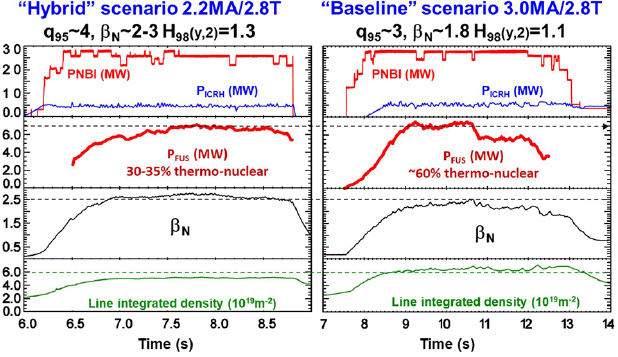
Figure 1. Time traces of the two main scenarios for achieving the target of 15 MW of fusion power for 5 s [12]. In the second box from the top, the equivalent fusion power is calculated as explained in the text using TRANSP. Note the difference in density βN, density and thermonuclear components between the two discharges. The beam–beam neutron component is negligible in both cases (<few %).
Download figure:
Standard image High-resolution imageIn 2016, during and just after the 2016 IAEA Fusion Energy Conference, encouraging results were achieved for the baseline scenario at 3 MA/2.8 T with an injected power of ~28 MW of neutral beam injection (NBI) and ~5 MW of ICRH (figure 1, right). ~3 × 10¹⁶ neutrons s−1 could be achieved for more than five energy confinement times (~1.5 s) making an equivalent fusion power of ~7 MW as computed with TRANSP [15], shared by 40% beam–target and 60% thermal–thermal fusion power.
Here, the equivalent fusion power for a D–T pulse is computed by TRANSP as in [16] assuming equal power from a neutral beam in deuterium and tritium in the deuterium scenario considered. In addition, in the JET calculation, the neutral beam fractional energies are taken into account and deuterium and tritium concentrations are forced to be the same (50% deuterium–tritium mix). In these calculations, no credit is taken for the alpha heating produced or fot possible favourable isotopic effects on confinement.
These equivalent fusion power performances have been achieved by lowering the injected gas rate at high power, thus accessing lower collisionality in the core and achieving high rotation at the H-mode pedestal. Lower particle throughput has been achieved by means of a combination of gas and edge-localized mode (ELM) pacing pellets injection, which resulted in moderate high Z impurity accumulation with a better confinement than with gas fuelling alone. Together with the increase of input power (up to 33 MW), lower collisionality helped in decoupling the ion and electron channels in the core and higher Ti/Te also induced a positive feedback on the stabilisation of the ion temperature gradient turbulence. The positive feedback was stronger at high rotation, which was enabled by low gas injection [17]. The operation with the baseline scenario also confirmed that ICRH power up to 5 MW, aided by an optimised coupling to the plasma with appropriate edge fuelling, is essential to control the accumulation of high Z impurities in the plasma core (more details in section 2.4)
Similar results in terms of neutron yield and equivalent fusion power were obtained at a reduced plasma current but a higher normalised beta in the hybrid scenario (2.2–2.5 MA/2.8–2.9 T) (figure 1, left). In this scenario, real time control of the ELM frequency with gas injection has been introduced to help in flushing tungsten from the edge. ICRH core deposition also helps in controlling the electron density peaking which could in turn lead to W accumulation [18]. Particularly for the hybrid scenario, heavy impurity accumulation is driven by neoclassical convection enhanced by poloidal asymmetries, and is highly sensitive to the main ion density and temperature peaking. Multi-channel predictive modelling of the high-performance hybrid scenario (Ti > Te) reproduces central tungsten and nickel accumulation 1.5 s after the H-mode onset well, as observed in experiment [19]. The high-Z impurities are controlled by application of high power density ICRH power near the plasma axis by enhancing turbulent diffusion [20]. As reported previously [21], tearing modes can also impact the discharge performance, therefore control was attempted by q profile tailoring. At βN = 2.4 (feed-back controlled using NBI power) m = 1 magnetohydrodynamic (MHD) activity and tearing modes can be avoided for 3.5 s using q profile tailoring by means of beam timing and current ramps and will be further optimized in the experimental campaigns in 2019. Further analysis using quasi-linear codes has shown that low density conditions in the hybrid scenario are an advantage for boosting the neutron rate generation [22]. In the hybrid scenario, enhanced fusion power is explained by the higher penetration of the NBI beams to the plasma core and a reduced ion temperature gradient (ITG) turbulence by fast ions when electromagnetic effects are taken into account [23, 24].
In both scenarios, strike point sweeping of 3.5 cm on the divertor tile is used and was proven to be efficient at mitigating the power peak heat load with PIN = 30 MW for 5 s [25]. Neon seeding has also been attempted as an additional method to mitigate the divertor heat load. Although it is efficient at reducing the temperature of the divertor target plates, the neon had the detrimental effect of increasing the central density, thus reducing the central temperature and resulting in a non-negligible penalty on the fusion yield [26]. Strike point sweeping is at present the main method to handle high exhaust power, but the use of neon seeding cannot be ruled out to reach the target of 5 s and is being considered in tritium plasmas if tungsten sputtering by tritium becomes intolerable [27]. Nitrogen seeding cannot be used in the JET tritium campaigns because the JET gas handing system does not handle tritiated ammonia and it could also contaminate the uranium beds of the JET tritium plant.
To fulfil the mission of alpha physics in the D–T phase, a third plasma scenario has been developed in view of it [28]. In next-step devices, including ITER, the impact of alpha-driven toroidal AEs (TAEs) on the redistribution of fast ions, causing a degradation of the plasma performance and losses to the first wall, remains to be quantified. It is therefore essential to prepare scenarios aimed at observing α-driven TAEs in a future JET D–T campaign. The main challenge for this type of study is to overcome the strong Landau damping from the neutral beams [29]. Discharges at low density, large core temperatures associated with the presence of internal transport barriers (ITBs) and good energetic ion confinement (i.e. Ip > 2.5 MA) have been performed in plasma with an elevated q profile (qmin from 1.5 to 3) in JET (figures 2(a) and (b)). As in the Tokamak Fusion Test Reactor (TFTR) [30], the afterglow scheme has been developed, consisting of switching off the auxiliary NBI power abruptly, and relying on the faster decay of the fast NBI ions compared to the fusion alphas to observe the α-driven TAEs in the afterglow phase, where alpha heating will be therefore dominating transiently. In tests of this strategy in deuterium plasmas, the presence of MeV ions driven by ICRH power has resulted in the experimental observation of n = 4, 5, 6 TAEs (figure 2(c)), also predicted by a stability calculation at ρ ~ 0.4 using the MISHKA code [31] (figure 3). Extrapolating this plasma to D–T shows that the obtained βTα achieved should be comparable, or even slightly larger, than what was achieved in similar successful TFTR experiments. This D–T prediction has been used for stability calculations using MISHKA and HAGIS [32] and core TAEs with toroidal mode numbers n = 4, 5, 6 have been found, thus matching those observed in the deuterium ICRH version of the pulse. The computation also predicts an alpha drive of typically 0.3%, which is comparable to that found in previous work [29]. These results give confidence that alpha driven TAEs could be observed in the future D–T phase of JET. In addition, the damping rates of AEs are also measured experimentally using the newly refurbished AE active diagnostic [33]. Good agreement has been obtained between simulations of damping rate with the GTC code and the measurements for weakly damped AEs probed by the antennas [34]. It should be noted that the impact of instabilities such as fishbones has also been studied using the HAGIS code and it shows that no more than 1% of alpha losses would be incurred by fishbones in JET D–T experiments [35] This is particularly important for the hybrid scenario, which is often subject to significant fishbone 1/1 activity in the plasma core.

Figure 2. (a) Time traces of the 'after-glow' scenario for alpha particle studies [28] featuring an abrupt interruption of the neutral beam injection. Box (b) shows the measured neutron rate (black line), and the TRANSP computed neutron rate components: beam–beam (b–b), thermal (th), beam–target (b–t) and total neutron rate. (b) Spectrogram of TAE modes measured by the magnetics in the after-glow phase. In deuterium, the ICRH power has been kept to 'illuminate' the fast particle driven modes. In D–T, the presence of alpha particles is predicted to produce the same type of modes (see (c) and the text). Reproduced courtesy of IAEA. Figure from [28]. © EURATOM 2018.
Download figure:
Standard image High-resolution image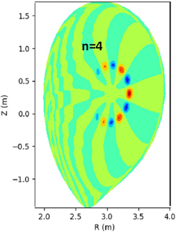
Figure 3. Toroidal Alfvèn eigenmode stability (TAE) calculation with the MISHKA code applied on the D–T prediction of the pulse of figure 2(a). Core TAEs with toroidal mode numbers n = 4 (represented here), 5 and 6 have been found matching those observed with the deuterium pulse with ICRH (figure 2(b)).
Download figure:
Standard image High-resolution image2.2. Scenario termination and disruptivity
For all the future D–T scenarios presented above, the control of impurity content is particularly demanding at the transition from the H-mode to the low confinement mode (L-mode) and during plasma termination [36], and it will also be critical in ITER [37]. Dedicated experiments were conducted in JET, specifically designed to examine the evolution of plasma parameters during the H-mode termination phase, the conditions under which W accumulation develops, and how it can be controlled with external actuators that are known to affect impurity transport, such as central electron heating or active ELM control (through pellet ELM pacing and vertical kicks) [38]. The experiments show that maintaining ELM control during the exit from the H-mode phase is a very effective way to avoid W accumulation and to achieve a smooth and well-controlled termination. Integrated fully predictive core–edge–scrape-off layer (SOL) transport modelling studies applying discrete models for the description of ELMs have been performed for the entire transition from stationary H-mode until the time when the plasma returns to L-mode, focusing on the W transport behaviour. Simulations have shown that the existing models appropriately reproduce the plasma profile evolution in the core, edge and SOL as well as W accumulation trends in the termination phase of JET H-mode discharges as function of the applied ICRH and ELM control schemes [39]. These studies have prompted the development of specific disruption avoidance schemes [40] and controllers using operation scenario modelling for handling the termination phases and minimising the risk of disruption at the H–L transition [41].
2.3. Fusion predictions for D–T scenarios
D–T performance predictions are particularly challenging since they require taking into account a large number of non-linear effects, including the heating deposition (both NBI and ICRH), fuelling sources, isotopic effects, fast particles, rotation and pedestal–core synergy.
For the calculation of the fusion power prediction, the initial task has been the development of the interpretative analyses of the reference discharges in deuterium plasmas. These are modelled using quasi-linear models (such as TGLF [42] or QUALIKIZ [43]). The impact of the different heating sources and mix on the performance are studied by a suite of codes such as JINTRAC [44] and CRONOS [45].
On this basis, D–T predictions have been carried out using the full JET power (NBI = 32 MW and ICRH = 8 MW) and CRONOS (TGLF) for both hybrid and baseline scenarios [46] using the pedestal scaling in  given in [47] (figure 4). The inclusion of the E × B shearing rate can generate an isotope effect, which improves confinement, as also obtained from gyro-kinetic simulations [48]. For the third scenario dedicated to the study of the alpha physics which exhibits an ITB (section 2.2), the transport simulations used the CDBM model [49]. Additional predictions to D–T have been using the Bohm-gyro-Bohm model for describing the core turbulence and the core-edge self-consistent interplay using EUROped [50]. According to these predictions made on the basis of the pulses shown in figures 1 and 2(a), 12–15 MW of fusion power can be produced at full input power for both the baseline and hybrid scenarios [46]. In addition, the predictions are showing that the electron heating in the plasma core by fusion alphas (~2–3 MW) will be comparable to electron heating by NBI, allowing a demonstration of alpha heating and other alpha particle effects (e.g. impurity screening, ITG stabilisation). The scenario for alpha physics studies (see above) could approach a fusion peak power of 10 MW (stars on figure 4). A separate prediction made with JETTO (QUALIKIZ), [51] did not use a pedestal scaling dependence upon the isotope mass but used stiff electron temperature gradient transport in the core. Despite these different physics hypotheses, both predictions are giving a very close estimate of the fusion power for both hybrid and baseline scenarios.

Figure 4. D–T fusion power predictions from the discharges shown in figures 1 and 2(a) to maximum input power (32 MW of NBI and 8 MW with ICRH) with the JINTRAC and CRONOS codes. Error bars account for the different bootstrap current models' total currents and isotope effects as described in the text (see also [46]).
Download figure:
Standard image High-resolution imageThe equivalent fusion power has been also computed over a large database of different scenarios by a simpler fusion power simulator that approximates the trajectory of the JET NBI system as a single pencil in the plasma equatorial plane for the beam deposition calculation, and determines the average fast ion slowing down rate ignoring finite thermal ion temperature effects. The orbit-averaged radial displacement due to the first orbit is estimated, after which orbit effects and radial transport are ignored. Fusion reaction rates are calculated for beam–target and thermal reactions, but beam–beam reactions and the effects of ICRF acceleration of fast ions (see section 2.4) are not included. As for the TRANSP calculation described in section 2.1, this calculation takes no credit for the additional alpha heating or the possible favourable isotope effect. It has also been validated by TRANSP using the two pulses shown on figure 1, and represented on figure 5 by the circled points in black. This figure allows a direct comparison with the fusion power achieved in DTE1 in various scenarios. Despite the lower total energy content but with more input power (up to 40 MW) and less dilution, the fusion power calculations are predicting that JET has already reached a larger equivalent fusion power than the achieved fusion power in DTE1 for the baseline scenario (red circles and triangles, respectively). In addition, the stationary scenarios (hybrid and baseline) are predicted to produce equivalent fusion power comparable to the transient fusion power achieved in the hot-ion H-mode in DTE1 [2] (orange open triangles) despite having significantly less total energy content. This difference can be explained both by the increased power (22 MW of input power in DTE1 instead of 40 MW planned for DTE2) and the lower dilution with the metallic wall (typically Zeff = 1.5 with the metallic wall instead of 2.5 with the carbon wall in DTE1).

Figure 5. Equivalent fusion power predictions using the fusion power simulator (see text) for the database of deuterium pulses run with the ILW overlaid with the actual fusion power achieved in DTE1 (triangles encircled by the dotted line). The colors are red for the baseline stationary scenario, green for the stationary hybrid scenario and blue for the ITB scenario. The orange triangles represent the transient hot-ion H-mode achieved in DTE1 [2] which is no longer part of the reference scenario for DTE2. The large green square and red circle are equivalent fusion power computed from the deuterium predictive runs with full power (40 MW total) for both hybrid (CRONOS + TGLF see [22]) and baseline (JETTO + QUALIKIZ see [55]) scenarios of figure 1. The scenarios of figures 1 and 2(a) are also identified by the three black small circles on this figure.
Download figure:
Standard image High-resolution imageRecently, predictive capability for D–T plasmas has been further enhanced by exploiting the European Transport Simulator (ETS) workflow developed by EUROfusion. The ETS allows transport equations in plasmas, including all hydrogenic species, to be solved at the same time. The NBI and ICRH source modules in the ETS have been thoroughly benchmarked with TRANSP and validated against JET data. [52]. Using this tool, the analysis and modelling of the onset of neoclassical tearing modes and their effect on heavy impurity transport has been performed during the main scenario [53].
2.4. The role of ICRH power in the development of the D–T scenario
ICRH power plays a particular role in the preparation for D–T and in the fusion power optimization. With the requirement of low gas puffing to preserve edge/pedestal confinement, ICRH heating is crucial for ensuring the control of high-Z impurities in the core of D–T scenarios. Fundamental to hydrogen minority heating (N = 1 H coinciding with N = 2 D resonance), ICRH was extensively used in the baseline and hybrid experiments aimed at preparing D–T scenarios. The N = 1 H/N = 2 D ICRH scenario has been shown to maximize central electron heating, thus providing peaked temperature profiles (figure 6, top) and increased turbulent transport to prevent W accumulation [54–56]. ICRH coupling is aided by dedicated gas injection in the main chamber magnetically connected with the ICRH antennas [57]. Although ICRH is the main tool used to prevent W accumulation in the centre of JET plasmas, application of ICRH can lead to an overall increase of the plasma impurity content, in particular in JET-ITER-like wall (ILW), tungsten (W) and nickel (Ni). This is in general attributed to enhanced plasma wall interactions (PWIs) and sputtering of the plasma facing components (PFCs) when applying ICRH. In JET, less high-Z impurity influx is observed with the so-called ITER-like antenna (ILA) [58] in comparison with the other antennas (A2 antennas). The enhanced PWI and the recipes to suppress their effects have been studied experimentally as well using antenna and RF-sheath models applied to JET [59, 60], such as the SSWICH code [61], and these conclude that PFCs on the antenna (such as the septum) could be unfavourable for minimizing the RF-sheath and the impurity production.

Figure 6. Comparison the effect on plasma electron and ion temperature of the different ICRH schemes N = 1 H minority and N = 1 3He minority and combined: Te (a) and Ti (b) from charge exchange spectroscopy. Note that the N = 1 3He minority is a more efficient scheme for ion heating depending on the 3He concentration used in the plasma [57]. Reproduced from [57]. CC BY 4.0.
Download figure:
Standard image High-resolution imageBy lowering the H concentration on the N = 1 H/N = 2 D ICRH scheme, deuterium absorption in neutral beam ions becomes dominant and the D–D fusion rate is enhanced with respect to the higher H concentration cases [62]. Modelling has shown that this effect is essential to reproduce the neutron rate and will contribute to boosting the D–D neutron yield in the range of 10%–25% in the hybrid scenario by channelling the maximum ICRF power to deuterium. However, this effect may not play such a large role in D–T since D–T fusion cross sections peak at a lower energy (~100 keV) than the D–D cross section. The calculations show that the fusion enhancement due to ICRH in D–T is about 5% in the hybrid scenario and negligible in the baseline scenario [63].
The N = 1 3He minority heating scheme has also been tested (figure 6, bottom) for enhancing ion heating (in D plasmas), although more experiments would be needed to conclude on its efficiency at preventing W accumulation. However, high ion heating power density near the axis can maximise the beneficial effect of ICRH against W central peaking and is predicted to provide a stronger effect than electron heating. [51]. In tritium and D–T plasmas, ion temperature peaking is predicted to be further amplified by the decrease in the ion–electron collision coupling, giving a positive isotope scaling for both stored energy and impurity screening. Efficient ion and electron heating was also obtained when using a combined heating scheme where both H and 3He minorities are simultaneously heated in the plasma centre by splitting the ICRH power between two frequencies [64].
Fundamental D minority heating in T-rich plasmas led to very efficient fusion performance in DTE1 ICRH-only plasmas [65]. Modelling indicates that this heating scheme applied to T-rich H-mode plasmas with neutral beam ions has a strong potential to achieve a high D–T fusion yield, and preliminary conceptual studies for its use in DTE2 are ongoing. Further experiments are planned in the next campaign with deuterium and tritium plasmas to validate the ICRH scenarios foreseen for DTE2 from the point of view of fusion performance and the prevention of core W accumulation.
Energetic species, such as injected NBI ions and fusion products, can also play the role of the 'third' species and resonate between the two cyclotron layers of the main ions, because of the Doppler shift in their resonance position. Indeed, effective ICRH heating of H–D mixed plasmas using D-NBI ions as resonant species was recently demonstrated on JET [66]. Figure 7(a) shows an overview of JET pulse #91256 (2.9 T/2 MA, H–D ≈ 85%–15%), where the neutron rate was increased by a factor of 10–15 when 2.5 MW of ICRH power (f = 25 MHz, dipole phasing) was added to 3.5 MW of D-NBI. The presence of a population of energetic D ions with energies of ~1–2 MeV during the combined ICRH + NBI phase was confirmed by neutron spectrometry (TOFOR) and γ-ray measurements. A consistent simulation of the TOFOR measurements for this advanced heating scenario was done with the TRANSP and SCENIC codes [67] (figure 7(b)). This novel three-ion ICRH scenario is an efficient technique for heating plasma mixtures. As proof-of-principle experiments on the tokamaks JET and Alcator C-Mod, a very small number of 3He ions absorbed nearly all the launched radiofrequency (RF) power and provided efficient heating of the background H–D mixed plasma [68]. In D–T plasmas, intrinsic 9Be impurity ions will inherently absorb part of the ICRH power and lead to bulk ion heating. Depending on the natural Be concentration in the discharge, the D–T plasma mix could be adjusted to align the ion–ion hybrid layer closer to the Be cyclotron resonance layer to enhance the Be absorption (three-ion scheme). Due to their larger atomic mass, ICRH-heated 9Be impurities will transfer an even larger fraction of RF power via Coulomb collisions to bulk D and T ions than the lighter 3He minority [69] and efficiently absorb radio-frequency power in a D–T = 50%/50% plasma in JET and ITER. Off-axis fundamental ICRH heating of tritium NBI ions from 〈ET〉 ≈ 70 keV (injection energy 118 keV) to 〈ET〉 ≈ 200 keV can become a promising scenario to maximize the D–T fusion reactivity and alpha power in future DTE2 experiments.
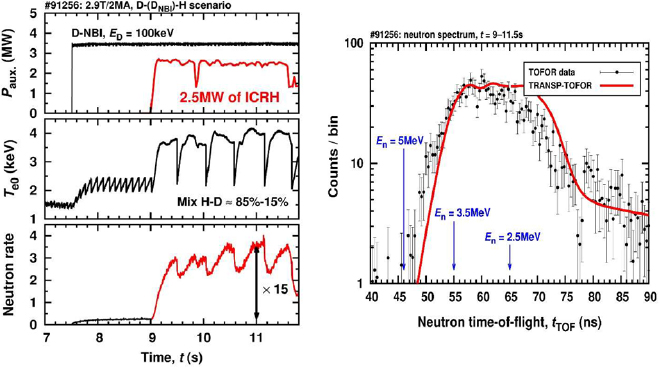
Figure 7. (a) Performance of the three-ion scheme D-(DNBI)-H scenario on JET-ILW (for H/D ~ 6, neo = 4 × 10¹⁹ m−3, f ICRH = 25 MHz, dipole phasing). Note the sharp increase of neutrons during the ICRH pulse. (b) For the pulse of figure 6(a), comparison of the TRANSP synthetic neutron spectroscopy time-of-flight diagnostics with the actual data of the diagnostics showing good agreement between the two. Reproduced courtesy of IAEA. Figure from [67]. Copyright 2018 IAEA.
Download figure:
Standard image High-resolution image3. D–T isotope physics in support of D–T
The impact of isotopes on confinement has also been assessed in detail in the analysis of the hydrogen and deuterium campaigns [70] in both the L-mode and H-mode. The future tritium campaign will uniquely complement the exploration of the isotope physics in fusion plasmas in support of the D–T mix phase.
3.1. L–H threshold dependence with isotope and divertor geometry
L–H power threshold (Psep = Ploss − Prad) studies have made use of about 200 pulses in JET-ILW spanning a range of plasma magnetic geometries, density and toroidal magnetic field values, hydrogen isotopes, ion species mixtures, effects from impurity seeding, and differences in heating and momentum sources [71]. It is notable that vertical target (VT) and corner/corner (CC) divertor geometry have about the same L–H power threshold, which is roughly a factor of two larger than in the horizontal target (HT) case, possibly because of the different x-point heights that modify the neutral circulation in the scrape-off [72]. In the VT and CC configurations, the results are consistent with the other experiments finding that PL–H in hydrogen is about twice that in deuterium (1/mi dependence), for the high-density branch [73] (figure 8). This would confirm that in future full tritium and D–T pulses, the power threshold for the transition could be decreased by the same scaling as illustrated in figure 8, as was also observed with carbon in JET during the DTE1 campaign in 1998 [74].

Figure 8. L–H power threshold for hydrogen and deuterium against the scaling of the power threshold [73] for vertical and corner divertor geometries. The L–H threshold in tritium is expected to decrease by 2/3 and by 1/3 in D–T.
Download figure:
Standard image High-resolution imageFor horizontal target data, access to the low-density branch is reached in both H and D, and significant differences depending on the heating methods (NBI or ICRH) have been identified. With the same shape, toroidal magnetic field, and plasma current, an isotope dependence is found for the density minimum of PL–H. Also in hydrogen, PL–H is much higher with NBI than with ICRH, while there is little difference in D, which is similar to the DIII-D results on the effect of torque [75]. The existence of a minimum density has also been investigated as in ASDEX Upgrade [76]. The power coupled to the ions computed from the JINTRAC suite of code [44] does not show a linear dependency with respect to density in the low-density branch [77].
PL–H was also studied in mixed species plasmas, yielding unexpected results. It was found that most of the variation of PL–H in H–D mixtures was for H concentrations less than 20% or more than 80%, with little variation in between. 4He fuelling into H plasmas was also performed, resulting in a ~25% reduction of the threshold with up to about 10% helium concentration. This reduction in L–H threshold in H–He mixtures may have a beneficial application for the non-active phase of ITER operations.
The formation of the edge transport barrier with isotopes has been investigated with the four-field drift-fluid model HESEL [78, 79]. The model can capture the observed isotope mass dependence of PL–H (PL–H α A−1.4 where A = mi/mH) linked with a faster development of the shear flow for higher mass but does not reproduce the behaviour of PL–H dependence with the H–D mixtures mentioned above.
3.2. Confinement and transport properties with the ion mass in the L-mode and H-mode
The results in the L-mode are of importance because of its impact on the ITER access condition to the burning phase and the current ramp-up in ITER. Confinement studies have found a weak dependence of τE,th on isotope mass demonstrated (~A0.15±0.05) not following gyro-Bohm transport (~A−0.5) (figure 9). This near independence with the ion mass has been confirmed experimentally using NBI heated L-mode plasmas in both H and D, with matched profiles of the dimensionless plasma parameters, ρ*, ν*, β and q in the plasma core confinement region [80]. Predictive core transport modelling with JETTO-TGLF [44] of the H and D identity pair is in good agreement with experiments for both isotopes, although H is over-predicted in non-identity discharges. The stiff core heat transport, typical of JET-ILW NBI heated L-modes, overcomes the gyro-Bohm scaling of gradient-driven TGLF, explaining the lack of isotope mass dependence in the core confinement region. The effect of E × B shearing on the predicted heat and particle transport channels is negligible for these low beta and low momentum input plasmas [70]. Other effects, linked with the isotope mass, may also break the gyro-Bohm scaling such as the impact of fast ions generated by the neutral beam on micro-instabilities [81–83], the multi-scale effect, i.e. the interplay between ion and electron micro-instabilities of different scales, [84], or collisionality [46].

Figure 9. Thermal confinement regression with the isotope mass using deuterium and hydrogen discharges in the L-mode at constant plasma average density, plasma current of 2.5 MA and toroidal field strength of 2.9 T. Reproduced from [70]. © 2017 CCFE.
Download figure:
Standard image High-resolution imageIn the type I ELMy H-mode, establishing the same densities in hydrogen as in deuterium could not be achieved. This resulted in hydrogen densities up to a factor of two below their deuterium counterparts showing a more significant reduction of particle confinement than in the L-mode [80]. This behaviour was not observed in JET-C (carbon wall), nor in JT60-U [85] suggesting that the different wall recycling conditions [86] may play a role on the pedestal. Using kinetic measurements, a global scaling of confinement with the ion mass, τE  A0.4±0.1 in type I ELMy H-modes is derived assuming Ti = Te [80] (figure 10). The A0.4 dependence of τth,e on the isotope mass is robust against the combination of variables chosen in the regression of the data [87]. The mass dependence is stronger than the standard ITER scaling IPB98(y ,2) (τE
  A0.19) [88] and opposite in exponent sign to the gyro-Bohm scaling. If confirmed with tritium, this strong scaling has favourable implications for ITER and for future D–T mixture plasmas. Particle confinement and angular momentum confinement are also found to scale strongly with ion mass (τϕ, τp,
  A0.5) [87].

Figure 10. Thermal confinement regression with the isotope mass using deuterium and hydrogen discharges in the H-mode [87] with a plasma current and toroidal field strength of 1.0 MA/1.0 T and 1.4 MA/1.7 T in hydrogen and 1.0 MA/1.0 T, 1.4 MA/1.7 T and 1.7 MA/1.7 T in deuterium. Reproduced courtesy of IAEA. Figure from [87]. Copyright 2018 IAEA.
Download figure:
Standard image High-resolution imageAs in the L-mode, H-modes have resilient profiles with 8.5 < R/LTi < 10.5 at mid-radius. Ti profile data show that Ti varies between 0.9 × Te and 1.4 × Te depending on density and power, and ITGs are dominant in the plasma core, as found by linear gyro-kinetic calculations with the GENE code [87]. The combination of larger pedestal pressure in deuterium and similar core R/LTi for both H and D suggests that, for this type of ELMy H-mode dataset, the favourable isotope effect on confinement originates in the pedestal and propagates to the plasma core via a near-constant critical temperature gradient. However, the effect of the isotope species on the pedestal is not yet understood and is under investigation.
3.3. Particle transport with isotopes: isotope mixing effect
In JET, experiments with mixed isotopes have provided a new insight on particle transport properties. In a multi-ion plasma, additional complexity is indeed introduced where ion profiles may respond to transients at a different timescale to the electrons. Two pulses with similar kinetic profiles Te, Ti, ne but different isotope compositions (nH/(nH + nD) ~ 0.86 and 0.33 respectively) have been produced [89]. The plasma isotope ratio H/D is controlled by changing the H/D ratio by gas dosing. Both pulses are type I ELMy H-modes with equal (8 MW) deuterium NBI heating producing strong core fuelling of pure deuterium. Despite the strong core deuterium fuelling by the neutral beams in both discharges, it is observed that the hydrogen profile remains as peaked as the deuterium profile even without the core particle source (figure 11), implying the presence of fast transport of the individual ion components. Such a behaviour has also been observed in JET using pellet injection instead of gas injection to control the H/D ratio and in trace tritium experiments [90] and in other devices in the past [91, 92]. In the ITG-dominated turbulent regime (the case in most existing tokamaks and future devices) non-linear and quasilinear simulations show that both the diffusion coefficient ratio Di/De and the pinch velocity ratio Vi/Ve can become much larger than unity for a normalised gradient length larger than ~6 [93]. Therefore, changes in isotope composition can occur at much shorter time scales than changes in electron density profiles. The experiments described above have been modelled with the JETTO integrated modelling suite [44] with QuaLiKiz for turbulent transport, and Te, Ti and ne predictions are in good agreement with experiments [94, 95] and support the statement that sources have a negligible impact on density peaking for multi-ion plasmas. In addition, electron density peaking has also been observed when neon is used as a seeding gas and this is explained by the same physics process [96]. This new effect is likely to have an important consequence for D–T fuelling and He ash removal in the JET D–T phase and later in ITER [97].
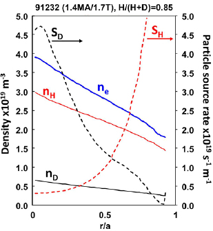
Figure 11. Comparison of electron, hydrogen and deuterium density profiles in a mixed plasma with H/(H + D) = 0.85 and different particle fuel sources (deuterium core fuelling by neutral beam and hydrogen edge fuelling by gas dosing). Note that the normalized gradients for both deuterium and hydrogen are comparable: R/LnH ~ R/LnD ~ 2.5 [89].
Download figure:
Standard image High-resolution imageFor single ion plasma, on the other hand, core density profile peaking and electron particle transport have also been studied by performing several dimensionless collisionality (ν*) scans in various plasma operation scenarios on JET with a gas puff modulation technique using high resolution diagnostics, distinguishing between the NBI source and inward pinch in their contributions to density peaking [98]. The NBI particle source contributes 50%–60% to the peaking in plasmas where Te/Ti ~1 and at ν* = 0.1–0.5 (averaged between r/a = 0.3–0.8) independent of ν*. These dimensionless ν* scans give the most appropriate data for model validation. TGLF simulations are in good agreement with the experimental results with respect to the role of NBI particle source versus inward pinch in density peaking. GENE predicts flat or hollow density profiles for JET H-mode plasmas, thus giving a higher weight on NBI fuelling than experimentally observed. For Te/Ti ~ 1.5 and low βN H-mode conditions, both TGLF and GENE correctly predict the peaked ne profile. Overall the various modelling results give good confidence that these models can be used to predict density peaking in lower ν* plasmas.
3.4. Pedestal and ELM stability dependence with isotope mass
Fusion power is affected by the pedestal performance through its structure and its stability. This is in large part caused by the electron temperature and density pedestals' relative radial positions that tend to vary with plasma conditions, as reported in JET [99] and other devices [100]. In addition, JET-ILW tends to have a larger relative shift compared to JET-C, suggesting a possible role of the plasma facing materials in affecting the density profile location [101]. Stability analysis using the EUROPED model [102] shows an improvement of the pedestal stability, when the relative shift is reduced. This has been mainly ascribed to the increase of the edge bootstrap current [50]. For the optimization of the D–T scenario performance, the dependence of the pedestal structure on isotope mass is therefore an essential ingredient. A recent estimate of the impact of the density position on an ITER baseline scenario shows that the maximum reduction in the pedestal height is 10% while the reduction in the fusion power is between 10% and 40% depending on the assumptions for the core transport model used [103].
Recent JET-ILW studies [70] have identified several differences in the pedestal structure in hydrogen and deuterium plasmas. The transition from L-mode to type III ELMs and type III ELMs to type I ELMs is strongly impacted by the isotope mass, in agreement with previous results in the JET-C. Also, identical discharges at the same input power and gas injection rate show a lower pedestal pressure in hydrogen than in deuterium. This is primarily due to the lower density (and higher particle transport in hydrogen) as observed in the L-mode (section 3.1). The ELM frequency is also lower in D. A larger ELM frequency in H than in D may indeed contribute to a lower density and thus a lower pedestal confinement [104]. Neutral penetration alone does not explain the differences between H and D pedestal density and transport must be invoked as well. Neutrals can indeed impact on the stability calculation [103], however, the direct isotope effect on linear peeling–ballooning stability is small. Stability calculations are also strongly sensitive to the separatrix temperature, which may not be identical in H and D.
The transport mechanisms that produce energy and particle transport in the pedestal have been investigated through gyro-kinetic simulations, and analysis of the relative size of heat and particle fluxes in JET-ILW pedestals. Recent work [105] has attempted to constrain the interpretation of pedestal instabilities on the basis of contributions to different transport channels. Simulations of JET-ILW [44, 106] find that particle transport in the pedestal is small compared to heat transport, which may be consistent with kinetic ballooning mode marginal stability moderating the density profile, but other mechanisms may be needed to explain heat transport. Non-linear gyro-kinetic simulations of high current (3 MA) baseline scenario JET-ILW plasmas find that electron temperature gradient turbulence as well as ion-scale turbulence driven by ion temperature gradient modes can be significant contributors to heat transport in the pedestal [107].
3.5. Dependence of plasma wall interaction with isotope mass
After the ILW was installed, carbon levels reduced by more than one order of magnitude. This low carbon level has not changed, despite high power operation on W-coated carbon fiber composite tiles in the divertor, suggesting no significant change to the tungsten tile coatings. The future D–T experiments are therefore not likely to experience strong tritiated hydrocarbon production, contrary to DTE1 [108]. For the characterization, erosion and migration, several diagnostics are used routinely at JET: optical and imaging spectroscopy for the sources of eroded material [109], pulse resolved erosion/deposition measurements with quartz microbalance sensors (QMB) in remote areas of the divertor [110], thermocouples and infrared cameras for monitoring the heat load deposition onto the first wall components, and Langmuir probes for measurements of ne and Te in the divertor region and for the characterisation of the divertor detachment. The analysis is supplemented by Monte-Carlo codes (ERO2.0 [111] and WALLDYN [112],) used for the simulation of the global material erosion and deposition.
The erosion of W by plasma (H/D/T) and intrinsic (Be) and extrinsic impurity (such as seeded gas, nitrogen or argon) sputtering determines both the lifetime of divertor components and the impact on plasma performance as it governs the W impurity source, therefore affecting W influx to the confined plasma region, which is also determined by other factors, for instance screening. Sputtering yields and fluxes as a function of impact energy are strongly dependent on the plasma conditions (such as edge temperature) and should also include the interplay between intra- and inter-ELM. The isotope effect on Be erosion by hydrogenic ions is so far poorly studied since most of the dedicated JET experiments were in D plasma. However, binary-collision approximation SDTrimSP simulations [113] allow prediction of the potential isotope dependences for the physical sputtering (figure 12) and thus give an insight of how sputtering may impact the integration of the main D–T scenarios with the W/Be wall. In particular, it is apparent that in D–T and T, tritium impact on W sputtering will become larger in the inter-ELM phases and in the L-mode. Intra-ELM erosion by tritium can increase by an order of magnitude with respect to hydrogen, and may amplify the level of tungsten sputtering by Be impurities [114, 115].

Figure 12. Isotope (H: green; D: blue; T: dotted red line) effect on Be and tungsten sputtering yields computed by the code SDTrimSP [114] for various phases of plasma scenarios. Note the higher tungsten sputtering by tritium in the intra-ELM phase as well as the increased Be sputtering by tritium leading to an increased tungsten sputtering by Be (in black).
Download figure:
Standard image High-resolution imageErosion and deposition were studied in the JET divertor during the JET-ILW campaigns using marker tiles analysed before and after the campaigns. The erosion/deposition patterns show profound changes compared to JET-C. The main sink for impurities is at the inner divertor, where the most deposition and fuel retention occurs [116]. The total material deposition rate in the divertor decreased by a factor of four to nine compared to the deposition rate of carbon in JET-C, and the deuterium retention in the divertor decreased globally by a factor of 10–20. Tritium retention is expected to follow the same pattern as confirmed by the analysis of tritium from the D–D reaction in plasma facing components [117]. Deposits on the inner divertor consist predominantly of beryllium (typically 5.0 × 10¹⁹ atoms cm−2 of Be to 0.3 × 10¹⁹ at cm−2 of D) [118] with 5% and 20% of carbon and oxygen, respectively, and small amounts of Ni and W [119]. Charge exchange neutral erosion is found to be the main source of nickel, whereas the erosion of divertor plasma facing components is the main source of tungsten. The tungsten sources come mainly from the outer divertor (1023 atoms per campaign), the top of the outer divertor, (1021–1022 atoms) and coating imperfections and fatigue cracking. The deposition rates in the inner and outer divertor corners and in remote areas decreased substantially and deposition is often only observed in valleys of the rough tile surfaces. These findings are consistent for all three ILW campaigns despite the considerable differences in strike point positions and heating powers [120].
In JET with the ILW experiment, beryllium erosion originating from the main chamber is measured by filtered BeII light emission from the JET wide angle camera and emission spectroscopy observing BeII (527 nm) viewing the inner wall. Beryllium erosion has been successfully modelled by ERO2.0 using the full 3D geometry of the inner wall, the SOL flows of the main plasma from EDGE2D-EIRENE and the plasma experimental kinetic profiles. The results have been validated successfully by comparison to the synthetic reconstruction of the camera image [112]. In addition, the spectroscopy viewing the inner wall has also provided material for the code validation for different operational phases: limiter, L-mode, and H-mode, including the charge exchange neutral contribution and the drifts. Chemically assisted physical sputtering (releasing Be–D molecules) is a source of uncertainty in this modelling which is not yet fully taken into account because of the lack of sputtering yield data. However, the good agreement with the respective observations confirms the validity of the model and qualitatively confirms the significance of Be migration into the divertor, in particular to the top of the inner baffle (figure 13), which is in line with post-mortem analysis results. This provides a firm basis for ITER predictions [114].
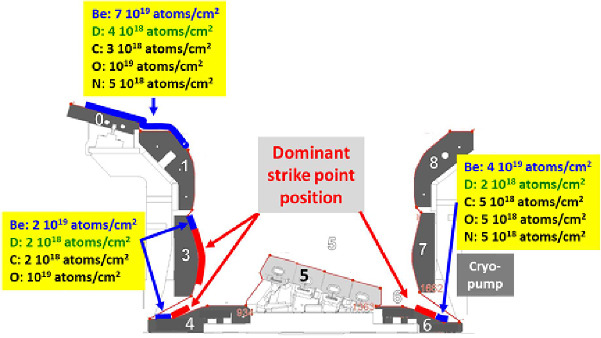
Figure 13. Material deposition patterns in the divertor after three JET campaigns [121] with the ILW and their relation to the dominant strike point locations. Note that the maximum deposition occurs on the inboard side on the top of the divertor baffle (tiles 0 and 1).
Download figure:
Standard image High-resolution imageIn JET-ILW and in other metallic devices, it has been shown that W gross erosion in the divertor averaged over the entire campaign is governed by the intra-ELM phase of the H-mode [121]. Gross tungsten erosion is observed in situ by the particle flux from the tungsten I line emission and the measurements modelled using ERO [122]. It has been found that in-between ELMs, deuterium ions have too low an energy for tungsten sputtering and thus only beryllium impurity ions lead to tungsten erosion. In contrast, during intra-ELM phases the sputtering is dominated by deuterium ions by ~70% (over Be sputtering ~30%), which are assumed to have high impact energy due to the ELMs. With tritium, the effect of ELMs on erosion is likely to increase and lead to more tungsten erosion by ELMs (figure 14). Tungsten emission on the divertor plates is also observed on camera using two interference filters of different bandwidths centered on the wall interaction emission [123]. Thanks to this new technique, the intra-ELM erosion is quantified (7 × 10¹⁸ W atoms/ELM) in typical 3 MA/2.9 T H-mode pulses with 21 MW of input power. This shows that inter-ELM tungsten atom fluxes have a strong in/out divertor asymmetry by typically a factor of 18, thus making the outer divertor tiles net W erosion areas. In the case of the inner divertor, net W sputtering is dominated by the intra-ELM erosion. W gross erosion measured by spectroscopy is indeed comparable in both divertor legs in the intra-ELM phase. Spectroscopy amounts to a W gross erosion of 40–60 g and post-mortem analysis a W net erosion of 2.4–4.8 g, thus corresponding to a re-deposition fraction of more than 90% averaged over both phases and averaged over the JET campaigns [115]. W sputtering fluence per ELM was modelled in deuterium and hydrogen plasma [124]. Depending on the plasma pedestal temperature W sputtering flux is lower in hydrogen than in deuterium plasmas due to the lower Be ion flux to the target because of the lower main chamber Be source and higher sputtering threshold for protons than for deuterons. This is consistent with QMB measurements in the divertor showing increased deposit by a factor of 1.5 to 2 in deuterium with respect to hydrogen [125].

Figure 14. Calculation of the amount of tungsten atoms per ELM for each isotope assuming free streaming transport during the ELM crash and typical plasma conditions with 0.5% of beryllium in the plasma with Bt = 3.0 T and nePED = 1 × 10²⁰ m−3.
Download figure:
Standard image High-resolution image4. Technical and operational preparation for the D–T phase
4.1. Key upgrades for the development of D–T scenarios
In recent years, important upgrades have been made on the JET NBI system in preparation for the D–T phase. In 2014, following the successful installation of new beam injectors [126], the full energy ion dump curved end plate power handling capabilities and fatigue life have been reviewed, redesigned and then replaced in the last shutdown. The new curved end plate design includes a threefold increase in water flow, giving improved cooling performance, in addition high strains caused by the heat flux are relieved by the introduction of slotting, thus improving fatigue life. These new plates give confidence that the design goal of more than 34 MW of injected deuterium beam power can be achieved. Also, for tritium operation, prediction of beam power fractions has been carried out [127] suggesting that more than 2 MW of tritium beam power can be achieved with the new injectors, thus giving up to 16 MW in deuterium and 17 MW in tritium for each beam box. This will therefore provide a significant increase in input power (by ~12 MW) with respect to the 1997 DTE1 campaign.
For tritium fuelling, a total of five tritium introduction modules (TIMs) have been installed at JET, one on top of the machine, one at the mid-plane and three in the divertor region [128]. The design was heavily inspired by the unique tritium valve used in DTE1. Gas flow rates from the old valve were insufficient to meet the demands for the future T or D–T campaigns, so the new modules incorporate high flow piezo-valves with local tritium storage. Since no human intervention or serviceability to the TIMs is foreseen during the tritium experimental campaigns, their design have incorporated redundancy, reliability, secure operation and conformity to JET specific design, inspection, testing and safety case requirements.
New feedback control algorithms have been designed for the ILA for phase control and second stage matching, thus extending the range of the operation to lower (29 MHz) and higher (51 MHz) frequencies than previously achieved and allowing more flexible and reliable operation. Operation with coupled power levels up to 2.8 MW and voltages up to 40 kV was achieved in 2016 [129].
For the complete exploitation of the JET ILW and to take full benefit from deuterium–tritium experiments on JET, a set of diagnostic system refurbishments and upgrades [130] have been deployed. JET can now rely on a comprehensive set of techniques to measure the neutron yield, neutron spectra and fast particles and is now equipped with vertical and horizontal lines of sight for neutron spectrometry, allowing the separation of RF, NBI and thermal contributions as shown in figure 7(b). Various gamma ray spectrometers are expected to provide unique data to codes for simulating the contributions of the trapped and passing fast particles. The redistribution of the alphas and fast ions, by various instabilities, can be measured with the gamma ray cameras. A new scintillator probe and refurbished Faraday cups will be able to relate the fast particle losses to the MHD instabilities. Also, given the importance of ion temperature measurements for D–T campaigns, the charge exchange instrumentation has been upgraded to improve the throughput and allow the simultaneous measurement of impurities and fuel-ion charge exchange. Synthetic diagnostics are being added to the most routinely used codes, for easier comparison to diagnostics data and to facilitate the interpretation of plasmas in the coming experimental campaigns, in support of the experiment execution. From a technological perspective, the planned D–T campaign will provide a unique opportunity to test ITER relevant diagnostic technologies, by performing measurements in hostile environments since the expected neutron flux at the first wall (1016 n cm−2) is comparable to that of ITER behind the blanket [131].
4.2. Real time control in support of D–T operation
With the objective of increasing the robustness and duration of D–T scenarios, several new plasma control schemes have been designed and will be tested and optimised in deuterium plasmas in 2019.
During tritium and D–T campaigns, both the tritium inventory and neutron budget are severely limited. Hence, real-time detectors have been developed for an early termination of underperforming discharges so as to reduce consumption. Based on normalised confinement and neutron rate indicators, these so-called 'dud' detectors can be used to trigger an alarm and a safe plasma termination. [132]. In D–T campaigns, the isotope control relies on visible spectroscopy for inferring the isotopic ratio at the plasma edge in real time and specific gas flow control schemes have been designed to manage the injection with the new five tritium gas injection modules and ensure the requested fuel mix (figure 15).
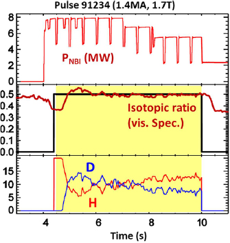
Figure 15. Typical example of the real time control of the isotope ratio at H/(H + D) = 0.5 using edge gas dosing of the H and D isotopes.
Download figure:
Standard image High-resolution imageFor ensuring that the target of 40 MW of input power is sustained for 5 s without damaging the first wall, an extensive real-time protection system monitoring the surface temperature of PFCs has been developed [133]. The imaging system comprises four wide-angle views, four tangential divertor views, and two top views of the divertor. In this way, it covers 66% of the first wall and up to 43% of the divertor. This is supervised by a powerful software package analysing the origin of heat load events and a hot spot management tool allowing the set-up of specific thresholds and assertion times depending on the type of event. Importantly, since D–T operation will cause the failure of camera electronics located in the torus hall [134], the images of two key camera systems have been relayed outside of the JET biological shield.
ELM frequency control using pellet injection or gas dosing has been used together with βN control for stabilizing the scenario discharges [12]. Plasma protection from radiation peaking to prevent the discharge from collapsing by excessive high Z radiation is also commonly used and detachment control is being explored in support of scenarios with radiative layers [135].
4.3. Fuel recovery and pumping
For the purpose of fuel recovery and cleaning, reliable isotope ratio measurements are essential for assessing the level of tritium in the vessel. The isotope ratio obtained from residual gas analysis signals agrees in general with optical spectroscopy measurements in the divertor [136] and provides an isotopic ratio accuracy of 0.5%. Determination of recycled hydrogen isotopologues released in the W divertor (H2, H–D, D2) and from the main chamber wall (the former plus Be–D, Be–T, Be–H) allows assessment of the local isotope ratio with accuracy below 0.5% [137].
Also, a new strategy for reducing the T wall inventory below 1% has been prepared [138]. This procedure will be first validated in hydrogen to reduce the inventory of deuterium below 1% prior to the tritium campaign in order to avoid excessive D–T neutrons in this phase. It also involves one week of vacuum vessel baking at 320 °C, combined with isotopic exchange by hydrogen glow discharges and ion cyclotron wall cleaning [139]. This procedure closely mimics the ITER wall cleaning planned strategy. In addition, the baking phase will be followed by plasma pulses in the optimized configurations to access to the deposits at the divertor baffles. Gas from baking and conditioning phases are collected by the JET Analysis Gas Handling System. To analyse the collected gas, the primary tool is a gas chromatograph coupled with a mass spectrometer with several separation columns and detectors meaning it is possible to analyse all six hydrogen isotopologues (H2, HD, HT, D2, D–T, T2), He, neon, air components and hydrocarbons [140].
The impact of isotope mass and divertor configuration on the divertor conditions and neutral pressures has been addressed by modelling for various isotopes [141]. The results show that a change from hydrogen to deuterium as the main fuel decreases the neutral mean free path, leading to higher neutral density in the divertor. A continuation of this study into tritium is expected to yield a further increase of rollover densities at detachment when compared to deuterium and hydrogen plasmas. This effect indicates that the isotope ratio control may also be different in H–D and D–T.
4.4. Calibration of 14 MeV neutron detectors
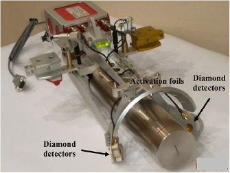
For D–T operation, calibration of the JET neutron monitors at 14 MeV neutron energy has been performed using a calibrated 14 MeV neutron generator deployed inside the vacuum vessel by the remote handling system. The neutron generator (figure 16) was equipped with two previously calibrated diamond detectors and activation foils [142, 143] which continuously monitored the neutron emission rate during the calibration. The monitoring activation foils were retrieved at the end of each day for decay γ-ray counting, and replaced by fresh ones. About 76 h of irradiation, in 9 d, were needed to scan the neutron generator through 73 different poloidal and toroidal positions and calibrate both the neutron yield monitoring systems available at JET, namely the 235U fission chambers and the activation system using the 93Nb(n, 2n)92mNb and 27Al(n,α)24Na activation reactions.
Figure 16. Neutron generator deployed inside the JET vacuum vessel on the remote handling arm. The two single crystal diamond detectors and the activation foils are symmetrically hosted in the support around the neutron generator, at the same distance from the target center. Reproduced courtesy of IAEA. Figure from [144]. © 2017 EURATOM.
Download figure:
Standard image High-resolution image
Neutronics calculations have been performed using the MCNP code [144] and a detailed model of JET to derive the response of the neutron detectors to D–T plasma neutrons from the measured response to the generator neutrons, also taking into account the anisotropy of the neutron generator and the presence of the massive remote handling system and other calibration circumstances. These calculations have used a comprehensive geometrical description of the neutron generator and a validated neutron source routine producing neutron energy-angle distribution for the neutrons emitted by the neutron generator [145].
The calibration factors for a D–T plasma have been determined to within ±6%–8% total uncertainty for the activation system and to within ±5% for the fission chambers. The difference between the fission chamber responses to D–D and D–T neutrons is within the uncertainties of the derived. The same conclusion can be derived for T–T neutrons, which are emitted in an almost intermediate energy range, between 1– 9 MeV. This result has important consequences for operations with D–T plasma mixtures with varying concentrations of T: in fact, fission chambers, having a flat response, always measure the total neutron yield (D–D + T–T + D–T) whereas the 14 MeV neutrons can in any case be discriminated by the activation system using the 93Nb(n,2n)) reaction which has a threshold at about 10 MeV. The calibration factors of the two independent systems will be compared and validated during full D–T operations (producing almost only 14 MeV neutrons) when both the fission chambers and activation system will independently measure the same D–T yield.
The experience gained and the lessons learnt are particularly valuable for the 14 MeV neutron calibrations in ITER.
4.5. Operation with tritium
There are a number of additional technical requirements (compared to deuterium and hydrogen) to operate JET with tritium gas including high D–T neutron flux and neutron activation [146]. Unlike usual gases supplied by gas bottles (e.g. deuterium, hydrogen, neon, argon), tritium is stored in uranium beds and will be supplied by the tritium plant in to one or two neutral beam boxes and five new tritium introduction modules (see section 2.1). The torus hall atmosphere will be under low pressure to limit the spread of tritium in case of accidental tritium release. Access will be restricted to key operational areas of the JET building and tightened access restrictions are also applied to computer networks. During operation, the divertor and neutral beam cryo-pumps will be regenerated after every operational day.
In preparation for the future tritium and DTE2 campaigns at JET, an eight-week technical rehearsal of the procedures and systems to be used in the tritium operation (without the use of tritium) has been performed [146]. The rehearsal demonstrated that JET is still capable of carrying out tritium experiments safely. In addition, an extra three weeks of plasma operation rehearsal with and without power are planned before tritium is introduced in the machine.
For the forthcoming tritium and D–T campaign, it is planned to inject about 450 g into the vessel. The tritium plant contains a maximum of 60 g. Tritium is pumped from the vessel by the cryogenic system. Hydrogen species are first separated from molecular tritiated molecules (tritiated water, hydrocarbons, etc) and then tritium is isolated in the chromatograph from hydrogen and deuterium. The molecular tritiated species are also processed separately so that, in the end, 100% of the tritium pumped is recycled and reused for the experiments [147, 148].
Tritium accountancy is an essential part of the tritium operation and the D–T safety case limits the tritium on the torus and neutral beam cryogenic panels to 11 g (44 bar × litre). The expected tritium gas is approved 2 weeks before the operation and the gas inventory monitored routinely by dedicated software. Since JET has also a limited 14 MeV budget of 2 × 10²¹ neutrons, in order to limit the activation of the vessel, the neutron budget is also carefully monitored. Predictions of neutron activation have been validated by past periodic measurements of the dose rate inside the JET vessel and by sophisticated shutdown dose rate codes [135].
5. Outlook
The active preparation of JET for the D–T campaign provides an incomparable source of information for the physics basis of D–T plasmas and the future operation of ITER. JET experimental and analysis campaigns have strengthened the preparation of the next tritium and D–T campaigns. Both baseline and hybrid operational regimes have produced promising results (more than 7 MW of equivalent fusion power), while remaining compatible with the ILW. In support of the scenario a huge step forward in the understanding of the isotope physics has been achieved. This would not have been the case without a strong focus towards D–T. In addition, the operational preparation for the D–T phase has now reached a high-quality level, tackling issues that had not been addressed in non-tritium compatible device such as neutron calibration, tritium handling, isotope control, wall erosion, etc.
JET is uniquely placed to provide a robust base for burning plasmas during its future D–T phase. The shutdown required to prepare for deuterium–tritium operations is now complete and despite recent delays, JET is ready to move towards a new domain with the new D–T phase. The main campaign elements until the end of 2020 are as follows.
- 1.A deuterium campaign for the preparation of high-performance scenarios and studies of disruption and runaway election mitigation using a new shatter-pellet injection system presently installed on JET as part of an ITER, EURATOM and US-DOE agreement.
- 2.Hydrogen and 100% tritium campaigns combined with reference pulses in deuterium for the study of isotope effects.
- 3.A deuterium–tritium campaign with the aim of producing 15 MW of fusion power for 5 s in stationary conditions in order to study the key physics aspects, such as those related to alpha particles, that a change from deuterium to a deuterium–tritium plasma may involve.
The JET programme will provide invaluable information for the non-activated phase of ITER, alpha particle and isotopic effects in plasma scenarios, particle and heat transport, retention, and wall cleaning. In parallel to the preparation of the D–T phase, JET is developing a strong program in support of the ITER research plan for disruption mitigation with the new shattered pellet injector and radiative layer studies. All these efforts will ensure a maximized output to ITER operation from its first plasma to the D–T phase.
Acknowledgments
This work has been carried out within the framework of the EUROfusion Consortium and has received funding from the Euratom research and training programme 2014–2018 and 2019–2020 under grant agreement No. 633053. The views and opinions expressed herein do not necessarily reflect those of the European Commission.