
Abstract
Bone is a highly vascularized tissue, in which vascularization and mineralization are concurrent processes during skeletal development. Indeed, both components should be included in any reliable and adherent in vitro model platform for the study of bone physiology and pathogenesis of skeletal disorders. To this end, we developed an in vitro vascularized bone model, using a gelatin-nanohydroxyapatite (gel-nHA) three-dimensional (3D) bioprinted scaffold. First, we seeded human mesenchymal stem cells (hMSCs) on the scaffold, which underwent osteogenic differentiation for 2 weeks. Then, we included lentiviral-GFP transfected human umbilical vein endothelial cells (HUVECs) within the 3D bioprinted scaffold macropores to form a capillary-like network during 2 more weeks of culture. We tested three experimental conditions: condition 1, bone constructs with HUVECs cultured in 1:1 osteogenic medium (OM): endothelial medium (EM); condition 2, bone constructs without HUVECs cultured in 1:1 OM:EM; condition 3: bone construct with HUVECs cultured in 1:1 growth medium:EM. All samples resulted in engineered bone matrix. In conditions 1 and 3, HUVECs formed tubular structures within the bone constructs, with the assembly of a complex capillary-like network visible by fluorescence microscopy in the live tissue and histology. CD31 immunostaining confirmed significant vascular lumen formation. Quantitative real-time PCR was used to quantify osteogenic differentiation and endothelial response. Alkaline phosphatase and runt-related transcription factor 2 upregulation confirmed early osteogenic commitment of hMSCs. Even when OM was removed under condition 3, we observed clear osteogenesis, which was notably accompanied by upregulation of osteopontin, vascular endothelial growth factor, and collagen type I. These findings indicate that we have successfully realized a bone model with robust vascularization in just 4 weeks of culture and we highlighted how the inclusion of endothelial cells more realistically supports osteogenesis. The approach reported here resulted in a biologically inspired in vitro model of bone vascularization, simulating de novo morphogenesis of capillary vessels occurring during tissue development.
Export citation and abstract BibTeX RIS

Original content from this work may be used under the terms of the Creative Commons Attribution 4.0 licence. Any further distribution of this work must maintain attribution to the author(s) and the title of the work, journal citation and DOI.
1. Introduction
In native bone, vasculature is essential for bone development, remodeling, and for fracture healing, and is pivotal in maintaining healthy bone tissue. Angiogenesis is a prerequisite for bone formation; in fact, both intramembranous and endochondral ossification occur in close proximity to vascular ingrowth [1–3]. During intramembranous ossification, capillaries invade the differentiating mesenchymal zone, whereas in endochondral ossification, hypertrophic chondrocytes recruit the infiltrating vasculature. Dysregulations of the interaction between bone and vasculature are the basis of different pathologies (e.g., avascular necrosis, osteoporosis, and Gorham-Stout disease) [1–5]. Moreover, a key obstacle to the in vivo translation of bone tissue engineering is the lack of vascularization within the engineered constructs [2, 4, 6]. A vascularized bone implant could be effectively used to treat large bone defects connecting the construct to the host vascular network to maintain viability and promote integration [1, 3]. Furthermore, vasculature would also be a key element that needs to be included to achieve a more realistic setting in in vitro engineered bone platforms to study bone biology, disease pathogenesis, and to test new potential drugs [7, 8].
In recent years, different attempts have been made to generate in vitro vascularized bone constructs by combining osteogenic precursors and vascular progenitors. Co-culture systems have been frequently adopted to simultaneously promote osteogenesis and vasculogenesis [3, 4]. Notably, intercellular communication supports simultaneous osteogenesis and angiogenesis in bone tissue engineering in a positive signal feedback loop [9–11]. In fact, human mesenchymal stem cells (hMSCs) secrete vasculogenic growth factors, such as vascular endothelial growth factor (VEGF) and platelet-derived growth factor, that enhance angiogenesis, whereas endothelial cells (ECs) produce bone morphogenic proteins, which promote osteoblastic differentiation of precursor bone cells [1, 12–15]. However, co-culture approaches are complex and parameters such as cell types, culture media, microenvironment, seeding methodology, and scaffold architecture and material will have a significant effect on the final outcome.
In the literature, several experimental approaches have been reported. Rao et al [16] co-cultured human umbilical vein endothelial cells (HUVECs) and pre-differentiated hMSCs using sequential-induction. First, they embedded hMSCs in collagen/fibrin/hydroxyapatite hydrogel microbeads and pre-differentiated them toward an osteogenic lineage for 14 d. Then, they encapsulated the microbeads into a collagen/fibrin vasculogenic phase containing a co-culture of undifferentiated hMSCs and HUVECs. The system was cultured for another 14 d in 1:1 v/v osteogenic and endothelial media. The authors demonstrated an endothelial network formation around the microbeads of engineered bone in 14 d. Similarly, Tsigkou et al [17] also used a sequential approach to create a vascularized bone graft model. First, they seeded hMSCS on a three-dimensional (3D) porous polylactic-co-glycolic acid (PLGA) scaffold and cultured them for 1 week in osteogenic medium. Then, a collagen-fibronectin gel containing HUVECs and hMSCs was added to the PLGA scaffolds. The constructs were cultured for an additional month in endothelial medium only. After 1 month of in vitro static culture a continuous and stable 3D network of HUVEC formed throughout the scaffolds which were then implanted subcutaneously in a mouse model. Using a different approach, Klotz et al [5] instead simultaneously co-cultured MSCs and endothelial colony forming cells in a bulk methacrylated gelatin (gelMA) hydrogel. After co-culture in 1:1 v/v osteogenic and endothelial medium, they achieved the formation of a vascular-like network within a developing bone-like matrix.
These works describe conventional techniques of fabrication for bone engineering scaffolds, which, along with others such as gas foaming, salt leaching, phase separation, freeze dying, etc, allow a fine control of pore size. However, control of pore interconnectivity is not possible and pores are stochastically distributed in the scaffold [18, 19]. In recent years, bioprinting has been increasingly used for scaffold fabrication to provide more control over scaffold design. Bioprinting uses computer-aided transfer processes to rapidly manufacture predefined complex constructs with precise control on the external and internal structures [19–21]. Thus, differently from conventional techniques, bioprinting has the capability to accurately fabricate interconnected porous structures, controlling key factors in scaffold fabrication, such as composition, pore geometry, size, and interconnectivity [4, 21] that are essential to creating organized constructs with different cell types.
In this work we aim to develop an in vitro engineered vascularized bone model to study crosstalk between blood vessel morphogenesis and osteogenesis during construct development. To this end, we first realized a bone construct based on a gelatin-nanohydroxyapatite (gel-nHA) 3D bioprinted scaffold with an interconnected pore network seeded with hMSCs subjected to osteogenic differentiation. Then, we included lentiviral-GFP transfected HUVECs to form a capillary-like network within the 3D bioprinted scaffold pores.
2. Materials and methods
2.1. Materials preparation
The biomaterial ink is composed of type A gelatin from porcine skin (Sigma-Aldrich), nanohydroxyapatite (nHA) (nanoXIMHAp, Fluidinova) and genipin (Challenge Bioproduct Co.). A 10% w/v solution of gelatin in deionized water (milliQ) was prepared by stirring on a heated plate at 50 °C for 30 min. nHA was added to the gelatin solution at a concentration of 50% w/v and the mixture was sonicated for 3 min with a VC130 sonication probe (130 W, Sonics and Materials INC.). Genipin was then added to the gel-nHA solution at a final concentration of 0.2% w/v and sonicated for 1 min. The mixture was prepared fresh before each printing as the workability window after genipin incorporation was about 40 min [22]. As a sacrificial support material, Pluronic acid F-127 (Sigma-Aldrich) was used. A solution at 20% w/v in deionized water was prepared by the previously described 'hot technique' [23].
For the development of the vascularized bone construct, HUVECs were resuspended in a hydrogel made of gelMA [24] and fibrin gel 1:1 v/v. Lyophilized gelMA was purchased from Cellink and a 10% w/v solution was obtained in a 0.15% w/v lithium phenyl-2,4,6-trimethylbenzoylphosphinate (Sigma-Aldrich) solution in PBS 1X (Gibco). For the fabrication of fibrin gel, a Tisseel Fibrin Sealant kit (Baxter) was used. Fibrin was dissolved in a sealer protein solution at a concentration of 100 mg ml−1. Thrombin was dissolved in a 40 mM CaCl2 solution at a concentration of 1 g l−1. Fibrinogen solution and thrombin solution were mixed 1:1 v/v to produce fibrin gel.
2.2. Scaffold fabrication
Bone scaffolds were fabricated with a piston-driven extruder 3D bioprinter, developed at the research center 'Enrico Piaggio' of the University of Pisa (figure 1(a)). The gel-nHA biomaterial ink presents low viscosity and low yield stress, and the crosslinking time of gelatin with genipin is relatively long (∼48 h). These factors do not allow for direct printing [25, 26], hence we bioprinted gel-nHA into a sacrificial support material (bioplotting technique) of Pluronic acid (figure 1(b)).
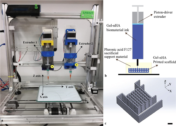
Figure 1. (a) Piston-driven extruder 3D bioprinter used to fabricate the scaffolds. (b) Schematic of the bioplotting technique used to print wood-pile scaffolds with vertical and lateral pores; a sacrificial support material provides a support to the biomaterial ink during the printing avoiding the collapse of the scaffold. (c) Wood-pile scaffold CAD model designed in Solidworks® with lateral branches to prevent material deposition during no-print movements; scale bar = 1 mm.
Download figure:
Standard image High-resolution imageA wood-pile scaffold with an interconnected pore network was designed in Solidworks® exported as a .stl file and sliced by Slic3r® that automatically generated the GCode for the 3D bioprinter. To avoid unwanted material deposition during no-print movements, external branches were added to the CAD model (figure 1(c)). The dimensions and printing parameters are reported in tables 1 and 2, respectively.
Table 1. Dimensions of the designed wood-pile scaffold.
| Parameter | Dimension/deg. |
|---|---|
| External dimensions | 17 × 17 × 5.2 mm |
| Fiber width | 0.8 mm |
| Inter-fiber distance | 1.8 mm |
| Fiber height | 1.2 mm |
| Axial pore size | 1 mm |
| Lateral pore size | 1.2 mm |
| Angle between fibers | 90° |
Table 2. Main printing parameters set in Slicer® to obtain the desired GCode.
| Parameter | Dimension/rate |
|---|---|
| Layer height | 0.4 mm |
| Print movement speed | 8 mm s−1 |
| No-print movement speed | 10 mm s−1 |
| Flow rate | 130% |
| Nozzle diameter | 0.7 mm |
After printing, the scaffolds were kept in the support material for 48 h, until full crosslinking was achieved (figures 2(a)–(c)). Then, they were placed at 4 °C for 2 h to liquefy the Pluronic acid [23, 27] and gently washed in deionized water to eliminate any leftover support. External branches were then removed with a surgical blade (figures 2(d), (e)). Finally, 4 mm diameter cylinders were cored from the scaffolds (figure 2(f)) and stored at 4 °C until use. High resolution images of the cylindrical cores were taken with an upright stereomicroscope (Olympus SZX16) (figures 2(g)–(j)).
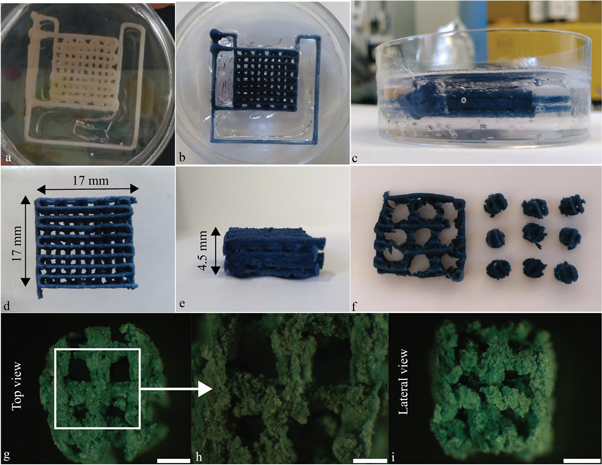
Figure 2. Post processing of the bone scaffolds. (a)–(c) Scaffolds were kept in the support material for 48 h. Pictures were taken (a) just after the printing and (b), (c) 48 h later, after crosslinking. The color change is a consequence of the genipin–gelatin reaction and the deep blue color marks the end of the crosslinking. (d), (e) Scaffolds after removal of Pluronic acid F-127 and cutting of the lateral branches with a surgical blade. (f) Scaffold 4 mm diameter cylindrical cores. (g)–(i) High magnification images of the cores in (g), (h) top and (i) side views showing axial and lateral pores, respectively. (g) and (i), scale bar = 1 mm; (h) scale bar = 500 μm.
Download figure:
Standard image High-resolution image2.3. Scaffold characterization
2.3.1. Morphological analysis
Cross-sectional images of the cored scaffold were obtained by microCT (Skyscan11®, Bruker) using a 0.25 mm aluminum filter, 52 kV source voltage, and 800 μA source current. The scaffold was rotated 360° degree with projection image acquisition every 0.5 degree. Projection images were reconstructed into cross-sectional images by NRecon® software and a 3D reconstruction of cored scaffold was then obtained by ITK-SNAP®.
Porosity, pore interconnectivity, scaffold fiber width, and size of lateral and axial pores were evaluated by a script developed in-house, based on the image processing toolbox of Matlab® (The Mathworks Inc.), and compared to the CAD model to evaluate the printed scaffold shape fidelity.
Briefly, cross-sectional images were binarized using the Otsu algorithm. Pixels that represented scaffold fibers were considered as background (pixel value equal to 0), whereas pixels that represented the scaffold's pore network were considered as an object of interest (pixel value equal to 1). The 'bwconncomp' function was used to identify connected components, belonging to the pore network, on the entire image stack. Then, the connected component with the largest number of pixels, namely the scaffold's pore network, was visualized in a 3D image using the 'patch' function.
2.3.2. Swelling test
Five cylindrical scaffold cores were weighted dry, then placed in 1 ml of PBS at 37 °C. Weighting was repeated after 15, 30, 60 90, 120, 180, 240, 300, and 1440 min. Swelling for each time point was calculated as (equation (1)):

where wi is the weight at the ith time point while wo is the dry weight.
2.3.3. Compressive test
The compressive modulus of dry and swollen (1 h in PBS at 37 °C) scaffold cores was evaluated using a Zwich Roell Z005 testing machine (triplicate measurements for each condition, test parameters are shown in table 3). A Feret diameter was used to estimate the scaffold's cross-sectional area. A linear fitting from 0%–5% strain for each sample's stress–strain curve was used to obtain the compressive modulus. A statistically significant difference between dry and swollen scaffolds was evaluated with a t-test (p value <0.05).
Table 3. Parameters used for the compressive test.
| Parameter | Measure |
| Final compression | 30% |
| Number of cycles | 1 |
| Deformation rate | 1% of initial height s−1 |
| Load cell | 100 N |
2.4. Development of a vascularized in vitro bone model
2.4.1. Cell culture
2.4.1.1. hMSCs
hMSCs were extracted from femoral heads of patients, undergoing total joint arthroplasty with Institutional Review Board approval (University of Washington and University of Pittsburgh). hMSCs extracted from nine different donors were cultured in monolayer culture with growth medium (GM; Gibco™ FluoroBrite™ Dulbecco's modified Eagle medium, fetal bovine serum (10% v/v), penicillin/streptomycin/fungizone (2% v/v), sodium pyruvate (1% v/v), and glutaMAX® (1% v/v)). The GM was changed every 3 d until 80% confluence. Cells were used at passage four.
2.4.1.2. HUVECs
HUVECs were purchased from Angioproteomie and expanded in monolayer culture with endothelial medium (EM; endothelial growth basal medium 2 supplemented with an EGM-2 Bullet kit (Lonza)). The EM was changed every 3 d until 80% confluence. Cells were used at passage five.
2.4.2. Scaffold seeding and culture
Scaffolds were UV sterilized for 1 h and incubated overnight at 37 °C and 5% CO2 in GM. Three different pools of hMSCs derived from three donors (nine donors total) were used to seed the scaffolds, each in triplicate (50 μl of 2 * 106 cells ml−1 of hMSCs suspension/scaffold, corresponding to 105 hMSCs/scaffolds). Scaffolds were cultured in 12 well plates with 3 ml of GM renewed every 3 d.
After 7 d, GM was substituted with osteogenic medium (OM = GM supplemented with 0.1 mM of ascorbic acid, 10 mM of β-glycerophosphate, 0.1 μM of dexamethasone, and 10 nM of 1,25-dihydroxy vitamin D3) to initiate osteogenesis.
After two weeks of osteogenic differentiation, the macropores of the scaffolds were filled with a 1:1 solution of fibrin gel and gelMA with or without HUVECs (see below for vascularized constructs fabrication). Then, constructs were cultured for two additional weeks in 12 well plates with 3 ml of medium, renewed every 3 d, under different medium conditions for a total of three groups as follows: (1) condition 1, bone constructs with HUVECs (see below) cultured in 1:1 OM:EM; (2) condition 2, bone constructs without HUVECs cultured in 1:1 OM:EM (control); and (3) condition 3, bone constructs with HUVECs cultured in 1:1 GM:EM (control) (table 4).
Table 4. Experimental conditions starting at day 14.
| Experimental condition | # | Cell types | Media |
|---|---|---|---|
| 1 | hMSC differentiated to osteoblasts + HUVECs | Osteogenic medium + endothelial medium 1:1 v/v | |
| 2 | hMSC differentiated to osteoblasts | Osteogenic medium + endothelial medium 1:1 v/v | |
| 3 | hMSC differentiated to osteoblasts + HUVECs | Growth medium + endothelial medium 1:1 v/v |
2.4.2.1. Vascularized bone construct fabrication
A 4:1 ratio HUVECs:hMSCs suspension was prepared at a final concentration of 106 cells ml−1 in a 1:1 solution of fibrin gel and gelMA. The macropores of each scaffold were filled with 55 μl of HUVECS:hMSCs-laden gelMA-fibrin gel hydrogel, and crosslinked in situ by exposure to UV-light (405 nm) for 2 min. A schematic of the fabrication process is shown in figure 3(a).

Figure 3. (a) Schematic of the process used to add HUVECs to the bone construct, filling the whole interconnected pore network within the scaffolds. (b) Experiment timeline for the development of a vascularized bone construct (conditions 1 and 3) and non-vascularized control (condition 2).
Download figure:
Standard image High-resolution imageExperiment timeline and time points are summarized in figure 3(b).
2.4.3. Live cell assay
Live cell assay was carried out after 24 h, 72 h, 7 d, and 10 d of initial hMSCs seeding. Scaffolds were covered with calcein AM solution (4 μM) and incubated for 45 min in the dark. At each time point, the top, bottom, and cross-sectional surfaces of the scaffolds were imaged with a fluorescence stereomicroscope (Olympus SZX16) to assess the uniform colonization of the scaffolds by hMSCs. Since genipin is strongly fluorescent in the red channel [28], the dead component of live/dead assay was not carried out.
2.4.4. DAPI-phalloidin staining
DAPI-phalloidin staining was carried out after 10 d of initial seeding and culture in GM with Alexa Fluor™ 488 phalloidin (ThermoFisher; excitation and emission wavelengths: 495 and 518 nm) and DAPI FluoroPure™ grade (ThermoFisher, with excitation and emission wavelengths: 358 and 456 nm). Scaffold fibers were also visualized in the red channel taking advantage of the intrinsic red autofluorescence of the scaffold material. Images were acquired with a fluorescence stereomicroscope (Olympus SZX16) and merged with ImageJ®.
2.4.5. Qualitative analysis of capillary-like network formation
After 14 d of culture (day 28 of the experiment), capillary-like networks formation by the HUVECs was imaged using the green channel of two fluorescence microscopes (Olympus SZX16, Nikon TE2000). Both the top and cross-sectional surfaces of scaffolds were imaged at different magnifications.
2.4.6. Histology and immunohistochemistry
At days 14 and 28, constructs were harvested and fixed in 4% paraformaldehyde in PBS, embedded in paraffin and sectioned in 5 μm thickness. Hematoxylin/eosin (H&E; Sigma-Aldrich) staining and CD31 (abcam, ab28364, 1:100 dilution) immunohistochemistry (IHC) were performed. For the IHC, endogenous peroxidase activity was blocked with 3% hydrogen peroxide in methanol and heat-induced antigen retrieval was carried out in a 0.01 M citrate buffer. Sections were incubated overnight with a primary antibody at 4 °C, and with a biotinylated horse anti-mouse/rabbit IgG secondary antibody (VECTASTAIN Universal Elite ABC Kit, Vector Lab) for 45 min at room temperature. Finally, the sections were counterstained with hematoxylin (Vector Lab).
2.4.7. Quantitative real-time PCR
Samples were flash frozen immediately after harvest by immersion in liquid nitrogen and stored at −80 °C until use. For total RNA extraction, samples were first pulverized by hammering in a liquid nitrogen-cooled biopulverizer (59012MS, BioSpec Products), and the powder obtained was added to Trizol (Invitrogen). RNA was then purified using the RNeasy Plus mini kit (Qiagen, Hilden) following the manufacturer's protocol. Reverse transcription with the SuperScript III kit (Invitrogen) and random hexamer primers was used to prepare cDNA. Quantitative real-time PCR was performed on the StepOnePlus thermocycler (Applied Biosystems) with SYBR Green Reaction Mix (Applied Biosystems).
Gene expression levels of alkaline phosphatase (ALP), runt-related transcription factor 2 (RUNX2), osteocalcin (OCN), bone sialoprotein II (BSP2), osteopontin (OPN), VEGF, and collagen type I (COL1) were analyzed. 18S rRNA was used as a housekeeping gene. Primer sequences are reported in table 5. Gene expression fold of change was calculated by the comparative cycle threshold (CT) method, using expression levels at day 0 as the reference for the 2−ΔΔCT calculation. A two-way ANOVA test with Tukey's post hoc analysis (multiple comparison) was used to pinpoint statistical differences of gene expression.
Table 5. Primer sequences used for the quantitative real-time PCR.
| Gene | Forward sequence 5' → 3' | Reverse sequence 5' → 3' |
|---|---|---|
| ALP | ATCTTTGGTCTGGCCCCCATG | AGTCCACCATGGAG CATTCT CTC |
| RUNX2 | CAACCACAGAACCACAAGTGCG | TGTTTGATGCCATAGTCCCTCC |
| OCN | TCACACTCCTCGCCCTATTG | GAAGAGGAAAGAAGGGTGCC |
| BSP2 | CGAATACACGGGCGTCAATG | GTAGCTGTACTCATCTTCAT GGC |
| OPN | TCACCAGTCTGATGAGTCTCACCATTC | TAGCATCAGGGTACTGGATGTCAGGT |
| VEGF | AGGGCAGAATCATCACGAAGT | AGGGTCTCGATTGGATGGCA |
| COL1 | TAA AGG GTC ACC GTG GCT | CGA ACC ACA TTG CCA TCA |
| 18 S | CCATCCAATCGGTAGTAGCG | GTAACCCGTTGAACCCCATT |
Control samples were collected after 7 d of hMSC expansion in GM (day 0) and after 14 additional days of differentiation in OM (day 14). Since the addition of HUVECs in experimental conditions 1 and 3 increased the number cells and might offset gene expression baselines, in the control samples for experimental conditions 1 and 3, HUVECs were added 12 h before the harvest of the constructs, as described before. Accordingly, experimental conditions 1 and 3 share common control samples (day 0 and day 14).
3. Results
3.1. Scaffold characterization
3.1.1. Pore connectivity
To evaluate the scaffold morphology, scaffold cross-sectional images were obtained by microCT. No collapse between layers with different bioprinting orientation is visible (figures 4(a), (b)). Scaffold 3D reconstruction made by ITK-SNAP® is shown in figure 4(c).

Figure 4. (a), (b) MicroCT section scans of cored scaffolds at different heights, the cored scaffold perimeter is highlighted. (c) 3D reconstruction of the scaffold by ITK-SNAP®. (d) 3D reconstruction of the interconnected pore network within the scaffold obtained by Matlab®.
Download figure:
Standard image High-resolution imageCross-sectional images were processed with a Matlab® script developed in-house, to create a negative 3D reconstruction of the scaffold microCT scan which represents the pore network (figure 4(d)). Analysis by Matlab® revealed that the scaffold pore network is interconnected with an axial square pore size of 0.92 ± 0.14 mm, a lateral pore size of 0.5 ± 0.15 mm, and a porosity of approximately 60%.
Table 6 compares the experimental measures with the CAD model to have an estimation of the shape fidelity.
Table 6. Comparison of scaffold fiber width and size of axial and lateral pores between the bioprinted scaffold and its CAD model.
| Scaffold CAD model | Bioprinted scaffold | |
|---|---|---|
| Fiber width [mm] | 0.8 | 0.52 ± 0.1 |
| Axial pore size [mm] | 1 | 0.92 ± 0.14 |
| Lateral pore size [mm] | 1.2 | 0.5 ± 0.15 |
3.1.2. Decrease in compressive modulus with hydration
Swelling tests were carried out in PBS 1X at 37 °C. The samples absorbed water without losing their original shape. A weight plateau was reached after 30 min (figure 5(a)).

Figure 5. (a) Percentage of swelling over time. Weight plateau starting point (30 min) is highlighted by a red line. (b) Comparison between compressive moduli of scaffolds tested just after the post processing and scaffolds tested after rehydration (swelling). *** p value <0.001.
Download figure:
Standard image High-resolution imageCompressive tests were carried out on the scaffold immediately post processing and after swelling, resulting in a compressive modulus of 36.4 ± 9.6 and 5.1 ± 2.3 kPa, respectively (figure 5(b)), with a clear decrease following rehydration.
3.2. Gel-nHA 3D bioprinted scaffold promotes cell proliferation.
Scaffolds were seeded with hMSCs (1 * 105 cells per scaffold) and live cell assay was carried out after 24 h, 72 h, 7 d, and 10 d. Since genipin is red fluorescent, it was not possible to carry out the dead component of the standard live/dead assay. Images of top, cross-sectional, and bottom scaffold surfaces at each time point are shown in figure 6. After 24 h, cells non-homogeneously attached to the scaffolds and several cell aggregates could be seen. After 7 and 10 d, scaffolds were completely and homogeneously covered by hMSCs.

Figure 6. Live assay of scaffolds at different time points for the top (left), cross-sectional (center), and bottom (right) surfaces. After 24 h, cells attached to the scaffolds inhomogeneously and several cell aggregates (red circles) were visible. After 72 h cells were homogenously distributed, and after 7 and 10 d, scaffolds were completely and homogeneously covered by hMSCs. Scale bar = 2 mm.
Download figure:
Standard image High-resolution imageAfter 10 d, DAPI-phalloidin staining was carried out. Green, blue, and red channels were used to image the cell cytoskeleton, cell nuclei, and scaffold fibers, respectively (figure 7). Cells stretching across the scaffold corners and starting to fill the space within the macropores were observed.
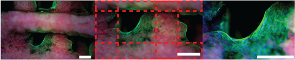
Figure 7. DAPI-phalloidin staining after 10 d of culture in GM. Photos were acquired with an upright stereomicroscope (Olympus SZX16) at different magnifications using all channels and merged with ImageJ®. Red channel: scaffold fibers (autofluorescent because of genipin); blue channel: cell nuclei; green channel: cytoskeleton. Red dotted lines mark the scaffold. Scale bar = 500 μm.
Download figure:
Standard image High-resolution image3.3. HUVECs form a capillary-like network
The organization of the GFP HUVECs was investigated 24 h and 14 d after seeding by fluorescent microscopy without the need for any additional dye (figure 8(a)). After 24 h, HUVECs were round and not connected, as expected, right after seeding in a hydrogel. By day 14, they formed complex and interconnected capillary-like networks (figure 8(b)); no qualitative differences between the networks of experimental conditions 1 and 3 were evident.
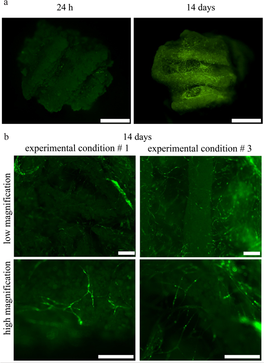
Figure 8. (a) Comparison of the organization of HUVECs in the bone constructs 24 h and 14 d after seeding in experimental condition 1. At 24 h HUVECs are few, rounded, and not organized, whereas at day 14 they are organized in capillary-like networks, both inside the macropores of the scaffolds and across the scaffold fibers. (b) Zoomed-in images of the HUVEC networks for experimental conditions 1 and 3 at two different magnifications. Capillary-like networks formed in both experimental conditions with no qualitative differences between them. (a) Scale bar = 2 mm. (b) Scale bar = 500 μm.
Download figure:
Standard image High-resolution image3.4. Vascularized bone construct maturation under different culture conditions
Samples were collected at all time points and analyzed by H&E histologic staining, CD31 immunochemistry, and quantitative real-time PCR (figure 3(b)).
H&E staining showed the cell morphology between hMSCs-derived osteoblasts and vascular-forming HUVECs (figure 9). Because of the presence of nHA, the gel-nHA scaffold stained a dark purple. However, this did not mask the deposition of bone-like matrix that stained pink and was clearly visible under all experimental conditions. Furthermore, HUVECs not only formed a capillary-like network within the scaffold macropores, but presented clearly identifiable lumens in experimental conditions 1 and 3 (figure 9). No qualitative differences in terms of number and size of the lumens were apparent between these conditions. When HUVECs were not present (experimental condition 2), osteogenically differentiated hMSCs were the only cells present. These cells remained close to the scaffold surface, and no lumen could be seen in the hydrogel filling the macropores.
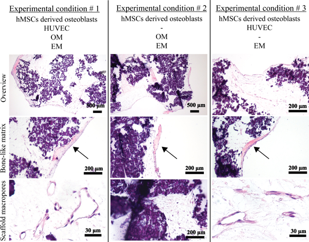
Figure 9. H&E staining of the constructs for all experimental conditions at different magnifications. Bone-like matrix is visible in all experimental conditions (arrows). In experimental condition 2 no tubular structures are present within the macropores, since no HUVECs have been included in the hydrogel, but only homogeneously distributed differentiated hMSCs. Tubular structures and lumens made by HUVECs are clearly visible in the scaffold macropores in experimental conditions 1 and 3.
Download figure:
Standard image High-resolution imageHUVEC lumen formation in experimental conditions 1 and 3 was further confirmed by CD31 immunohistochemistry (figure 10). Experimental condition 2 acted as a control where no cells were stained, as expected, since no HUVECs were incorporated in the hydrogel.

Figure 10. CD31 immunohistochemistry of the constructs for all experimental conditions. Staining of HUVECs within the scaffold macropores in experimental conditions 1 and 3 confirmed the formation of lumens by the HUVECs. In experimental condition 2 no staining occurred as no HUVECs were added.
Download figure:
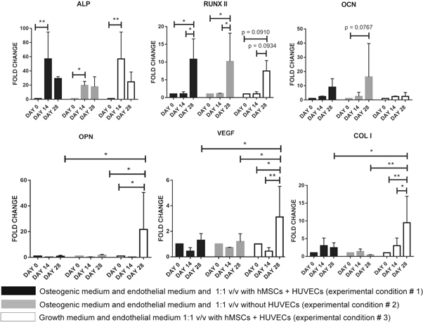
Standard image High-resolution imageGene expression analysis via quantitative real-time PCR was used to quantify osteogenic differentiation of hMSCs as well as the effects of crosstalk between hMSCs-derived osteoblasts and HUVECs. Statistical analysis was performed by a two-way ANOVA test with a Tukey's post hoc analysis (multiple comparison). The results are shown in figure 11. Overall, expression of the osteogenic genes tested increased over time. After 14 d in osteogenic medium, ALP overexpression was statistically significant for all conditions, and plateaued after 14 d. For all conditions, RUNX2 was expressed at the highest level at 28 d, with no statistically significant differences between experimental conditions. Although trending toward an increase, no statistically significant differences to day 0 was detected for the expression of OCN and BPS2 (data not shown). Notably, only in experimental condition 3 (with HUVECs and without osteogenic medium) was a statistically significant overexpression of OPN at day 28 observed, which was significantly higher than experimental conditions 1 and 2, where osteogenic medium was present. A similar trend was also observed for VEGF and COL1 expression.
Figure 11. Gene expression analysis for vascularized bone construct via quantitative real-time PCR. All time points and experimental conditions are reported. * = p value < 0.05, *** = p value < 0.01.
Download figure:
Standard image High-resolution image
4. Discussion
In this work we have developed a vascularized in vitro bone model combining hMSCs-derived osteoblasts differentiated on a 3D bioprinted gel-nHA scaffold, with HUVECs and hMSCs in a gelMA:fibrin gel hydrogel, and studied the effects of the osseous-vascular 3D co-culture. To this end, we implemented and standardized a purposely optimized bioplotting fabrication approach to create wood-pile, genipin crosslinked gelatin-nHA scaffolds. These materials possess ideal properties for our application for numerous reasons. First, both gelatin and nHA as well as their composite are biocompatible [29, 30], with good cell affinity [31, 32]. In fact, seeding hMSCs in our gel-nHA scaffold resulted in rapid cell adhesion and proliferation, and the scaffold surface was homogeneously covered after 7 d of culture as evidenced by the live cell viability assay (figure 6) and DAPI-phalloidin staining (figure 7). Moreover, nHA confers osteoinductive properties [30, 33], and as we have previously shown, the inclusion of nHA increases the scaffold compressive modulus by an order of magnitude [34]. Genipin proved to be an ideal crosslinker by virtue of its biocompatibility and low toxicity [31, 32]. Furthermore, we previously characterized the diffusion and reaction time of genipin into a gelatin matrix, identifying a workability window of 40 min for up to 0.5% w/w genipin/gelatin [22], which is well compatible with the workability window of extrusion-based bioprinting, as we planned to employ in this work. However, gelatin, like many other natural polymers, belongs to a class of materials challenging to 3D bioprinting [25]. Their low viscosity, low yield stress, and relatively long crosslinking time during or after fabrication, lead to poor shape retention properties. This is a major obstacle in creating 3D high reliability structures with an interconnected pore network, which can be overcome by bioplotting into a sacrificial material [20, 26]. In this approach, the biomaterial ink is extruded directly into soft, easily removable, shear thinning materials with high yield stress that act as a support matrix during the printing process, until crosslinking of the biomaterial ink is complete (figure 1(b)). Hinton et al used a slurry of gelatin microparticles as a sacrificial support material to successfully 3D bioprint complex structures of biologically relevant hydrogels such as alginate, fibrin, and Matrigel® [26]. To further improve biocompatibility for cell bioprinting, Highley et al developed a self-healing supramolecular hyaluronic acid-based material as a support to 3D bioprint a photocrosslinkable hyaluronic acid bioink containing hMSCs [35]. In our work, a gelatin slurry or a hyaluronic acid-based hydrogel were not viable options as genipin would react with their ammine groups, crosslinking the support and the gelatin biomaterial ink. Thus, we used Pluronic acid as the sacrificial support material which is deprived of an ammine group, has high yield stress, is inert to gelatin, biocompatible, stable at 37 °C, and easily removable [23, 27, 36]. To the best of our knowledge, this is the first time that Pluronic acid has been used as a sacrificial hydrogel support bath material for bioprinting.
By design, we aimed at producing a scaffold with interconnected macropores for a veritable in vitro vascularization. After fabrication, we characterized the scaffold morphology via microCT combined with an in-house developed Matlab® image analysis script (figure 4(d)). The scaffold fiber width decreased compared to its CAD model. This shrinking can be attributed to all the processes scaffold underwent after printing (i.e. crosslinking reaction, support removal, microCT analysis routine), which led to an important reduction of water content. Scaffold axial pores maintained the designed dimension, whereas lateral pores decreased by about 58% (table 6). The collapse of lateral pores due to gravity was minimized by bioprinting inside a sacrificial support material that sustained the extruded filament, preventing structural downfall. A partial decrease of lateral pore size was still an expected phenomenon. This decrease is due to the extrusion process itself. In fact, during biomaterial ink extrusion, the new outgoing filament pushes on the already deposited ones, leading to a reduction of lateral pore size. However, notably, image analysis by Matlab® revealed that the scaffold kept a continuous and interconnected pore network. This is a crucial feature for uniform cell seeding, facilitating nutrients transport and waste removal, and allowing scaffold vascularization [3, 6, 18, 37].
Native mineralized bone and vasculature are characterized by very different morphological and structural properties. Thus, to mimic these in vivo characteristics [4, 5], we employed distinct biomaterials with specific mechanical and chemical properties for concurrent engineering of the osseous and vascular components. As discussed above, the former is constituted by hMSCs undergoing osteogenic differentiation on the osteoinductive gel-nHA scaffold with an appropriate compressive modulus [4, 5]. The latter is generated from HUVECs embedded in a 1:1 v/v gelMA:fibrin gel hydrogel supporting ECs self-assembly. Fibrin gel is pro-angiogenic and easily remodeled by the HUVECs; however, it does not retain its shape, and has been described as having poor mechanical stability and suboptimal durability [38]. On the other hand, gelMA has good shape retention and tunable mechanical properties based on its concentration and degree of methacrylation [24, 39], and at low concentration it has been used has a support for in vitro vascular endothelial network formation [4, 5, 40]. Hence, we decided to use a fibrin gel:gelMA mix, to ensure high angiogenicity (fibrin gel) and good shape retention (gelMA). To the best of our knowledge, this is the first time this composite hydrogel has been used and we have achieved excellent results in terms of lumen formation (figures 9–10). Overall, we tuned gelatin to a stiff, osteoinductive material when combined with nHA, and to a soft, pro-angiogenic hydrogel when combined with fibrin gel, thus developing an integrated, novel approach that yielded remarkable osseous and vascular formation.
With respect to the development of bone tissue, we observed an intense pink matrix, stained by hematoxylin, in all samples (figure 9, arrows). We considered these structures to be newly formed osseous matrix, as they compare well with the histology of bone formation in engineered constructs implanted in vivo described by other groups [41–43]. Although the neo-bone we observe is limited in size compared to the in vivo studies, it is remarkable that it is even able to form to this extent in vitro.
According to literature, the formation, maturation, and in vitro long-term stability of capillary-like networks by ECs is contingent on ECs being co-cultured with MSCs [2, 4, 16]. In this context, MSCs act as pericytes in the neovascularization process, stabilizing and sustaining the developing vasculature [5, 38]. Consequently, a 4:1 ratio of HUVECs and hMSCs was introduced within the scaffold macropores of our model as it was well established to induce stable capillary-like network formation [5].
To develop a vascularized in vitro bone model in a single culture space, selecting effective timing and culture medium is pivotal. For instance, Rao et al [16] used sequential-induction, first culturing hMSCs embedded in a collagen/fibrin/hydroxyapatite microbeads in osteogenic medium for 14 d; then, they added undifferentiated hMSCs and HUVECs in collagen/fibrin microbeads and cultured the constructs in a 1:1 v/v ratio of OM:EM. At the end of the experiment, the authors observed interconnectedness between HUVECs across beads, but they did not report the presence of any lumen. Differently, Correia et al [2] used decellularized bone and fibrin gel as a scaffold and compared the effects of different sequences of OM and EM. They observed that osteogenesis for 4 weeks followed by 2 weeks of OM:EM culture cocktail does not result in any lumen, whereas, culturing for 2 weeks in EM followed by 4 weeks in OM:EM produced visible lumens and a satisfactory level of osteogenesis. The authors deduced that culturing HUVECs in OM:EM is detrimental for lumen formation and that it is necessary to first allow HUVECs to organize in a network prior to any osteogenic differentiation in order to achieve both vasculature and mineralized bone matrix in the same culture space. In our work, we first seeded hMSCs in a gel-nHA 3D bioprinted scaffold and cultured it in OM for 14 d. Subsequently, we poured HUVECs-hMSCs suspended in a gelMA:fibrin gel hydrogel within the scaffold macropores, and cultured the constructs for 14 d under different medium conditions (table 4). In our hands, the sequential OM followed by OM:EM culturing results not only in the interconnectedness of HUVECs as reported by Rao et al [16], but also in robust, large lumen formation and tubular structures, confirmed by H&E and CD31 staining (figures 9 and 10, respectively). This apparently contradicts the finding of Correia et al [2], although our initial osteogenic differentiation lasted only 2 weeks and not 4 weeks which might account for the difference in outcomes.
Furthermore, we observe the histology formation of new bone matrix even after the relatively short 4 weeks in culture (figure 9). In our work, while the first 2 weeks are the same for all conditions, OM:EM or EM are used for the remaining weeks. However, bone formation appears to be similar under all conditions, and HUVECs form robust lumens when cultured in either OM:EM or in EM only. Overall, in the sequential 2 + 2 week time course, OM does not appear to be detrimental to vasculogenesis and EM does not seem to negatively affect osteogenesis.
Over the years, several 3D bioprinting techniques (e.g., the extrusion-based system, inkjet printing system, and laser-based technique) have been used to precisely pattern ECs in 3D constructs for mono or co-culture systems. The ability to control the spatial distribution of ECs, especially in relation to their neighbors such as pre-differentiated hMSCs and smooth muscle cells (SMCs), is important to investigate cell–cell signaling pathways and to control cellular microenvironments [27, 44]. Wu et al [45] used biological laser printing (BioLP®) to create precise and defined HUVECs and SMC branches. This technique [46] allowed controlling the formation and orientation of HUVEC networks as well as the size and shape of their lumens. Differently, Cui et al [47] fabricated a microvasculature structure using a thermal inkjet printer. The authors deposited an EC-laden thrombin solution on a fibrinogen substrate by inkjet printing thus realizing a 3D tubular microvasculature structure that showed robust integrity and stability after 21 d of culture.
In this work, we aimed to study the crosstalk between HUVECs and hMSC-derived osteoblasts, focusing on hMSCs' osteogenesis, HUVECs' self-organization, and a capillary-like network formation. Thus, we did not use a computer-controlled deposition system but randomly seeded HUVECs in the scaffolds' pores to let them self-organize, and we used a sequential-induction approach discussed in detail above.
Finally, Tsigkou et al [17] used an even shorter osteogenesis phase. They developed a vascularized bone graft model by first seeding hMSCs in a 3D porous PLGA scaffold fabricated by sucrose leaching. After 1 week of culture in OM, an hMSC-EC mix in a collagen-fibronectin hydrogel was added to the PLGA scaffolds. These constructs were cultured in vitro just in EM and resulted in the formation of a stable endothelial network, which supports our findings. However, it should be noted that, differently from our work, Tsigkuo et al did not observe lumen formation in this first part of their work. In their study, the authors subcutaneously implanted the constructs, after 21 d of in vitro culture, in a mouse model used as an in vivo bioreactor. Already at 11 d post-implantation, the construct was vascularized and connected to the host blood vessels. Furthermore, 8 weeks post-implantation, grafts with EC and hMSC-derived osteoblast showed significantly more mineralization compared with grafts with hMSC-derived osteoblast only. Taken together with our observations, these findings reinforce the concept of close crosstalk between vascular and osseous components that support bone formation, as also observed in our work.
We have further explored phenotype commitment by testing gene expression for all conditions. Since we used biological triplicates for all conditions, a relatively high data variability in real-time PCR results was expected. In fact, scaffolds were seeded with three different sets of cells, i.e., three pools of cells each obtained by pooling three different human donors (for a total of nine different donors). Data obtained from each of the three pools were averaged to assess changes in gene expression due to each experimental condition. Notably, since biological replicates were used, the statistically significant differences we reported strongly suggest that our in vitro model is broadly valid irrespective of the specific cell source (donor) selected.
Overall, the upregulation of ALP and RUNX2 strongly suggests osteogenic commitment of the scaffold seeded hMSCs, as also supported by histology. ALP is an early marker of osteogenesis and it is consistently highly expressed by day 14, after which it plateaus consistently as in other reports in the literature [48]. RUNX2 is a master regulatory gene of bone development [49–51], and for all tested conditions it is significantly highly expressed at day 28. Notably, even when HUVECs and the differentiating hMSCS are co-cultured without osteogenic medium (experimental condition 3), between days 14 and 28, the upregulation of RUNX2 is only slightly decreased, but not statistically different from culture with the OM:EM media mix (experimental conditions 1 and 2). This suggests that, once osteogenesis is initiated in the first 14 d of the experiment, the co-culture of HUVECs and hMSCs alone is sufficient to support further osteogenic commitment. Previous work by Bidarra et al [13] also showed that the co-culture of HUVECs and hMSCs leads to an overexpression of RUNX2 even in the absence of OM, confirming our observation. However, although remarkable bone-like matrix was produced, the lack of significant upregulation of OCN and BSP2 (data not shown) suggests that the differentiated osteoblasts were not fully mature. In particular, no upregulation of OCN is present, neither between time points nor between experimental conditions. This is not surprising since OCN is a late osteogenic marker, expressed by fully differentiated osteoblasts and activated by RUNX2 [52], which in the constructs is only upregulated by day 28. Likely, a longer culture time would be required for elevated OCN expression. Nonetheless, we had already observed a trend of increase for OCN expression increase in experimental condition 2 where HUVECs were not part of the constructs. This is consistent with the work of Bidarra et al [13] who showed that OCN is more expressed in mono-cultures of hMSCs than in hMSC and HUVEC co-cultures. Moreover, we observed that the absence of osteogenic medium during vascular maturation in the last 14 d of differentiation (experimental condition 3) resulted in the markedly elevated expression of OPN, VEGF, and COL1.
Considering the existing literature on the interaction of OPN and VEGF in other models [9, 10], our findings suggest a potential positive feedback regulation between these genes that, to the best of our knowledge, has never been observed in a co-culture model. In fact, Chakraborty et al [9], studying breast cancer vascularization, described a positive feedback loop between OPN and VEGF. The authors showed that the administration of OPN to tumor cells in 2D triggers the increase of VEGF expression, and importantly, that VEGF in turn induces the overexpression of OPN in the same cells. Dai and co-workers [10] investigated the effect of OPN on the proliferation and organization of HUVECs. When OPN was administered in an in vitro culture, VEGF expression increased as well as HUVECs' proliferation, migration, and capillary tube formation in Matrigel®. The authors suggested that OPN directly activates the PI3K/AKT and ERK1/2 pathways inducing angiogenesis. Furthermore, the authors showed that the OPN-induced VEGF activates the same pathways of OPN, acting as a positive feedback signal. In our study, the overexpression of OPN and VEGF arises only when OM is not present (experimental condition 3), suggesting an inhibitory role of OM on VEGF expression. This agrees well with the findings of Freeman and colleagues [53], who reported increased production of VEGF when aggregates of chondrocytes, HUVECs, and hMSCs are cultured in GM compared to culture in OM.
5. Conclusion
In this study, we showed that a sequential-induction approach enabled vascular-osteogenic outcomes within the same culture space. First, we promoted osteogenesis of hMSCs seeded in a 3D bioprinted gel-nHA scaffold. Then, we induced the formation of a stable vascular network in the HUVEC-laden hydrogel filling the macropores of the scaffolds. This approach resulted in a biologically inspired in vitro model of bone vascularization, simulating de novo morphogenesis of capillary vessels occurring during tissue development. The bioprinted in vitro vascularized bone model may then be used to interrogate bone biology in healthy and pathological conditions and to test potential therapeutics. The approach reported here represents a major step towards the creation of progressively more realistic models that may include additional cell types, such as osteoclasts or osteocytes. Moreover, a natural development of our vascularized osseous construct is its combination with a chondral phase to create a veritable osteochondral model to explore the complex crosstalk occurring in the joint between cartilage, bone, and vasculature [4, 54].
Acknowledgments
We would like to thank Dr Paul Manner, University of Washington, for providing clinical specimens. This work was supported in part by the Ri.MED Foundation (Italy), the Children's Hospital of Philadelphia Research Institute, the Frontier Program in Airway Disorders of the Children's Hospital of Philadelphia and the European Union under the Horizon 2020 Framework Research Program SC1-PM17-2017 – Project OACTIVE – Grant Agreement 777159.